Linux5.10.198_User’s Manual_V1.0
Document classification: □ Top secret □ Secret □ Internal information ■ Open
Copyright
The copyright of this manual belongs to Baoding Folinx Embedded Technology Co., Ltd. Without the written permission of our company, no organizations or individuals have the right to copy, distribute, or reproduce any part of this manual in any form, and violators will be held legally responsible.
Forlinx adheres to copyrights of all graphics and texts used in all publications in original or license-free forms.
The drivers and utilities used for the components are subject to the copyrights of the respective manufacturers. The license conditions of the respective manufacturer are to be adhered to. Related license expenses for the operating system and applications should be calculated/declared separately by the related party or its representatives.
Overview
This manual is designed to help you quickly familiarize yourselves with the product, understand interface functions, and learn testing methods. It primarily covers the testing of development board interface functions, methods for flashing the image, and troubleshooting common issues encountered during use. During testing, certain commands have been annotated for better understanding, focusing on practicality and adequacy. For kernel compilation, related application compilation methods, and development environment setup, please refer to the “OK3562-UP4_Linux5.10.198_User’s Compilation Manual” provided by Forlinx.
There are five chapters:
Chapter 1. briefly introduces the development board’s interface resources, relevant driver paths in the kernel source code, supported flashing and boot methods, and key points in the documentation;
Chapter 2. describes two login methods: serial port login and network login;
Chapter 3. covers the desktop functions and QT interface functional testing, conducted via command-line operations;
Chapter 4. includes camera playback tests and video hardware encoding/decoding tests;
Chapter 5. details methods for updating the image to storage devices, allowing you to choose the appropriate flashing method based on your actual needs.
Additionally, the manual includes explanations of some symbols and formats.
Format |
Meaning |
|---|---|
// |
Explanation of input commands or output information: |
Username@Hostname |
root@OK-x-UP4: Development Board Serial Port Login Account; |
Example: Checking the Loading Status of the AW-CM358 Module Driver
root@OK-x-UP4:/# lsmod
Module                  Size  Used by      //View loaded module
moal                  696320  0
mlan                  487424  1 moal
root@OK-x-UP4: Username “root”, hostname “forlinx”. This denotes executing operations with root privileges on the Forlinx development board;
//: Denotes explanatory notes about commands or printed information; no input required.
Application Scope
The OK-x-UP4 development board currently offers documentation for the Linux operating system. This manual details how to test the functions related to Linux 5.10.198; please select documentation that matches the image installed on the development board. You can access software and hardware documentation through the cloud storage link provided by our company (please ask your sales representative for the download link).
Note: For further details, please refer to the OK3562-UP4 Linux User Data; the directory in which the user data mentioned in this document is located uses the OK3562-UP4 Linux User Data as its root directory.
Revision History
Date |
Version |
SoM Version |
Carrier Board Version |
Revision History |
|---|---|---|---|---|
11/03/2026 |
V1.0 |
V1.1 |
V1.3 and above |
User’s Manual Initial Version |
1. OK3562J-UP4 Development Board Description
1.1 OK3562J-UP4 Development Board Description
RK3562J is a low-power, high-performance processor based on the ARM64 architecture. It integrates four ortex-A53 cores, one Conrtex-M0 core, and an independent NEON coprocessor, making it suitable for applications in computers, mobile phones, personal mobile internet devices, and digital multimedia equipment. Connection method: Stamp hole. The main interfaces are shown in the figure below:
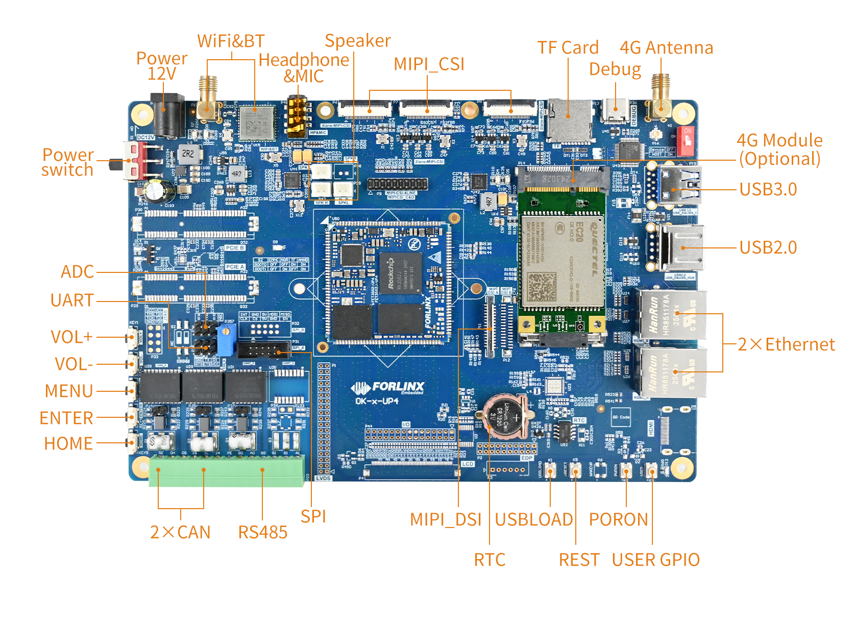
Front
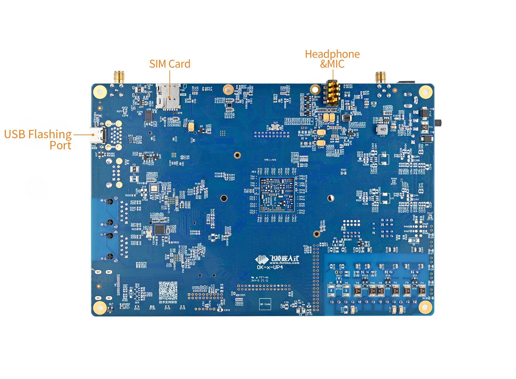
Back
Note: Hardware specifications are not covered in this software manual. Before development, please refer to the “User’s Hardware Manual” to understand the product naming and hardware configuration.
1.1 Linux 5.10.198 System Software Resources
Device |
Driver Source Code Location in the Kernel |
Device Name |
|---|---|---|
LCD Backlight Driver |
drivers/video/backlight/pwm_bl.c |
/sys/class/backlight |
USB Interface: |
drivers/usb/storage/ |
|
USB Mouse |
drivers/hid/usbhid/ |
/dev/input/mice |
Ethernet |
drivers/net/ethernet/stmicro/stmmac |
|
SD/micro TF card driver |
drivers/mmc/host/dw_mmc-rockchip.c |
/dev/block/mmcblk1pX |
EMMC Driver |
drivers/mmc/host/dw_mmc-rockchip.c |
/dev/block/mmcblk2pX |
Camera |
drivers/media/i2c/ov13855.c drivers/media/i2c/ov5645.c |
/dev/videoX |
LCD controller |
drivers/gpu/drm/rockchip/rockchip_drm_vop.c |
|
MIPI CSI |
drivers/phy/rockchip/phy-rockchip-mipi-rx.c |
|
MIPI DSI |
drivers/phy/rockchip/phy-rockchip-inno-mipi-dphy.c |
|
LCD touch driver |
drivers/input/touchscreen/goodix.c drivers/input/touchscreen/edt-ft5x06.c |
/dev/input/eventX |
RTC Real - Time Clock |
drivers/rtc/rtc-rx8010.c |
drivers/rtc/rtc-pcf8563.c |
Serial Port |
drivers/tty/serial/8250/8250_dw.c |
/dev/ttySX |
Button driver |
drivers/input/keyboard/adc-keys.c |
/dev/input/eventX |
LED |
drivers/leds/leds-gpio.c |
|
I2S |
sound/soc/rockchip/rockchip_i2s.c |
|
PMIC |
drivers/mfd/rk808.c drivers/regulator/rk808-regulator.c |
|
PCIE |
drivers/pci/controller/pcie-rockchip.c |
|
Watchdog |
drivers/watchdog/dw_wdt.c |
/dev/watchdog |
SPI |
drivers/spi/spi-rockchip.c |
/dev/spidev2.0 |
PWM |
drivers/video/backlight/pwm_bl.c |
1.2 eMMC Storage Partition Table
The table below details the eMMC storage partition information for the Linux operating system (The size of a block is 512 bits when calculating.):
Partition |
Name |
Offset/Block |
Size/Block |
Content |
|---|---|---|---|---|
N/A |
security |
0x00000000 |
0x00004000 |
MiniLoaderAll.bin |
1 |
uboot |
0x00004000 |
0x00002000 |
uboot.img |
2 |
misc |
0x00006000 |
0x00002000 |
misc.img |
3 |
boot |
0x00008000 |
0x00020000 |
boot.img |
4 |
recovery |
0x00028000 |
0x00040000 |
recovery.img |
5 |
backup |
0x00068000 |
0x00010000 |
|
6 |
rootfs |
0x00078000 |
0x00c00000 |
rootfs.img |
7 |
oem |
0x00c78000 |
0x00040000 |
oem.img |
8 |
amp |
0x00cb8000 |
0x00002000 |
amp.img |
9 |
userdata |
0x00cba000 |
userdata.img |
2. Fast Startup
2.1 Preparation Before Startup
Development Login methods: Serial login and network login.
Hardware preparations before powering on the system:
12V3A DC power
Debugging Serial Cable (Serial Login Use)
The debug serial port on the development board is a USB Type-C port. You can connect the development board to a PC using a Type-A to Type-C cable to check the board’s status information.
Ethernet cable (for network login)
Display screen — connect the screen according to the development board interface (optional if display is not needed)
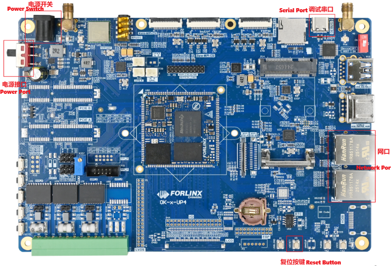
2.2 Driver Installation Failure
Use Software Data \ 3-Tools \ DriverAssitant _ v5.1.1.zip to install the rockchip driver
After extracting the package, run DriverInstall.exe directly. To ensure that the latest driver is installed, click Uninstall Driver first, and then click Install Driver.
Use Software Data \ 3-Tool \ CH343SER.EXE to install the serial port driver
2.3 Serial Port Login
The OK3562J-UP4 platform features a Type-C port for serial debugging and an onboard USB-to-UART chip. No additional USB-to-serial debugging tool is required, making the setup simple and convenient.
2.3.1 Serial Connection Settings
Note:
Settings: Baud rate 115200, 8 data bits, 1 stop bit, no parity/flow;
The serial terminal supports password-free login;
Software requirement: On a Windows PC, a serial terminal program must be installed. There are many serial terminal tools available, and you may use any one you are familiar with.
The following example uses PuTTY to illustrate the serial login procedure:
Step 1: Confirm the serial port number connected to the computer, checking the port number in Device Manager, based on the actual port recognized by the computer;
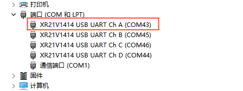
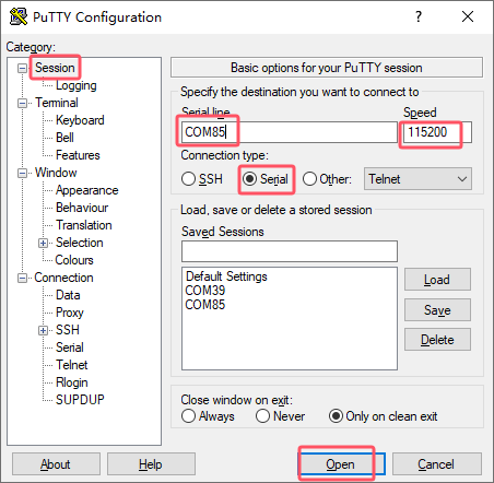
Step2: Open the putty and set the serial line according to the com port of the computer used. The baud rate is 115200.
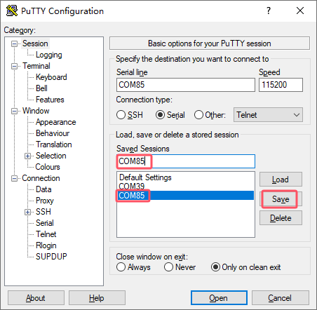
Step 3: After completing the above settings, enter the COM port number used by your computer in the “Saved Sessions” field (as shown in the following figure, using COM43 as an example), and save the configuration. Subsequently, when reopening the serial port, simply click the saved port number to directly apply the settings.
Step 4: Turn on the power switch of the development board. Boot messages will be displayed on the serial terminal, and the system will log in automatically without a password.
Starting input-event-daemon: done
root@OK-x-UP4:/# [   10.342583] Freeing drm_logo memory: 12008K
[   10.355181] file system registered
[   10.425017] read descriptors
[   10.425066] read strings
[08:00:09.560] seeing the first app
root@OK-x-UP4:/#
root@OK-x-UP4:/#
2.3.2 Common Issues (Serial Login)
For USB-to-serial port functionality, a driver is required (Software Materials\3-Tools\XR21_Win10_V2.7.0.0).
It is recommended to use a high-quality serial cable to avoid garbled output.
2.4 Network Login
2.4.1 Network Login Test
Note:
The Ethernet port is configured with a static IP address of 192.168.0.232 by default. For instructions on changing the static IP address, refer to Section 3.2.17 Ethernet Configuration;
The computer and the development board need to be in the same network segment during the test.
Before logging in to the network, you need to ensure that the network connection between the computer and the development board is normal. You can test the connection status between the computer and the development board through the ping command. Specific Operations:
Connect the eth0 of the development board to the computer via a network cable, power on the development board, and after the kernel starts, the Blue heartbeat light on the SoM will flash. After the network card connected to the computer starts normally, the network card light will flash rapidly. At this point, you can test the network connection;
Disable the computer firewall;
Temporarily disable the computer’s firewall (this is a general operation; specific steps depend on your Windows version);
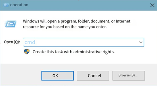
Open Command Prompt as administrator.
Press Win + R, type cmd, then press Ctrl + Shift + Enter to run Command Prompt as administrator;
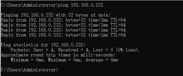
Data is returned, indicating that the network connection is normal.
2.4.2 SSH the Server
Note:
The Ethernet port is configured with a static IP address of 192.168.0.232 by default. For instructions on changing the static IP address, refer to Section 3.2.17 Ethernet Configuration;
Account: forlinx; password: forlinx;
Log in as the root user (password: root).
1. Use SSH to log in to the development board.
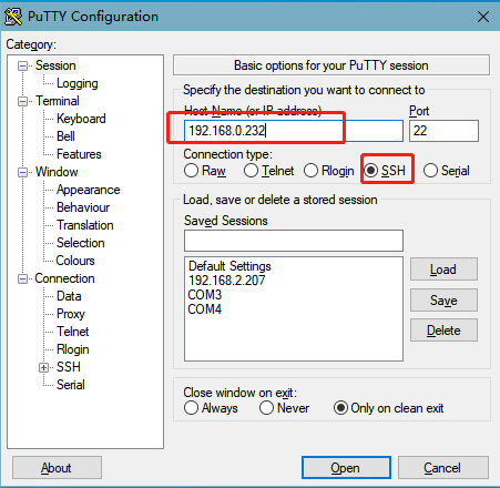
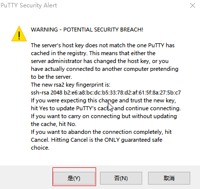
After clicking “Open”, a dialog box will appear. Click “Yes” to proceed to the login interface.
Login as:forlinx
[email protected]'s password:               //Follow the prompts to enter the password "forlinx"  and the account "forlinx".
forlinx@OK-x-UP4:~#
2.4.3 FTP and SFTP
Path: OK3562-UP4(Linux) Software Materials\3-Tools\FileZilla
The OK3562J-UP4 development board supports FTP SFTP services, which are enabled automatically upon startup. Once the IP address is configured, the board can be used as an SFTP server.
The following example, using SFTP, demonstrates how to perform file transfers using the FileZilla tool.
Install the file Zilla tool on windows and follow the steps shown in the figure below. The user name and password are forlinx.
Open the filezilla tool, click File, and select Site Manager.
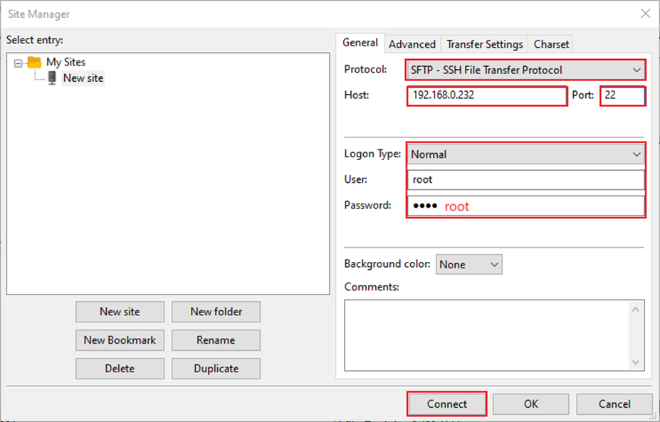
After successful login, upload and download operations can be performed.

2.5 Screen Switch
OK3562J-UP4 supports MIPI DSI display. At present, there are three ways to control the screen switch: uboot menu dynamic control; kernel device tree designation; QT UbootMenu application control.
2.5.2 Kernel Device Tree Specification
This method does not require a serial terminal connection. The system image is configured with the default desired settings, making it suitable for mass production. However, manual modification of the device tree is required, followed by regeneration of the system image.
Note: This method takes precedence over the U-Boot screen selection. After modifying the device tree, the U-Boot screen selection will no longer be effective.
The device tree path is: kernel/arch/arm64/boot/dts/rockchip/OK-x-UP4-common.dtsi
In the kernel source code, open the specified DTSI file and locate the forlinx-control node, as shown below:
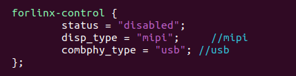
The node is disabled by default and needs to be changed to “okay” to enable it. Modify according to the screen requirements.
Parameter description:
Parameter |
Meaning |
|---|---|
status |
Describe the node status: disabled is to close the node, okay is to enable the node. |
disp_type |
Specify the MIPI display. |
You can modify the configuration parameters as required; once saved, the image must be recompiled.
2.6 System Shutdown
Under normal circumstances, the power can be turned off directly. However, if data is being stored or other operations are in progress, do not cut off the power unexpectedly, as this may cause irreversible file corruption. To ensure all data is fully written, you can execute the sync command to complete data synchronization before powering off.
Note: For products designed based on the SoM:, if unexpected power loss during use leads to system abnormalities, consider implementing measures such as power-loss protection in the design.
3. OK3562J-UP4 Platform Interface Function Usage and Testing
The OK3562J-UP4 platform provides excellent support for Qt, particularly for multimedia-related classes such as video decoding and playback, camera integration, video recording, etc. It achieves optimal performance by utilizing hardware encoding/decoding and OpenGL.
3.1 Desktop Function Testing
3.1.1 Interface Function Overview
After booting, the development board will display the following desktop:
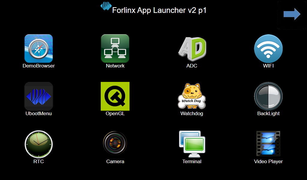
3.1.2 Hardware Decoding Experience
Click the desktop icon to open the video player.

Application Icons
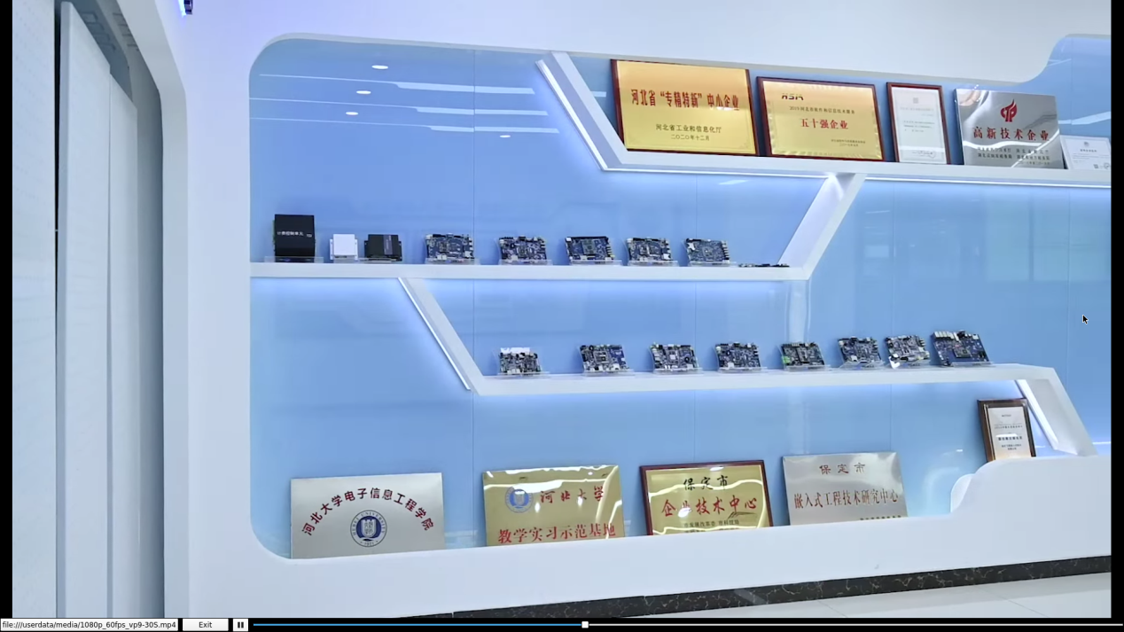
Note: The directory where the test video file is located:/userdata/media/.mp4.
3.1.3 OpenGL Test
OK3562J-UP4 supports OpenGL ES3.2, click the desktop icon for OpenGL testing.

Application Icons
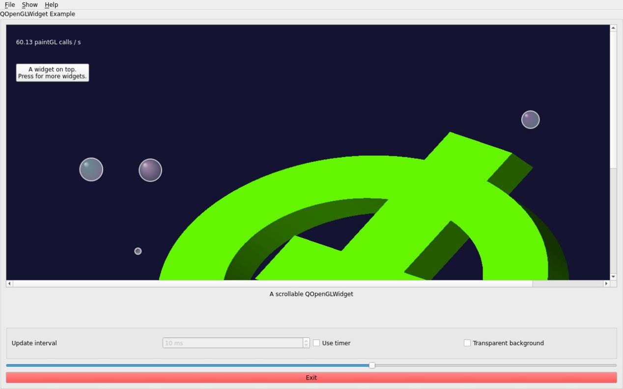
3.1.4 Music Playback Test
“musicplayer” is a simple audio test application that can be used to test whether the sound card functions normally and also serves as a simple audio player.

Application Icons
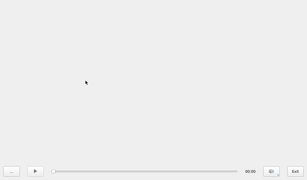
Application Interface
Click the button in the lower left corner and select the audio test file /userdata/media/test.mp3.
3.1.5 4G Test
Note: This test requires inserting a SIM card with Internet access. Please refer to section “ Command Line Function Test (4G)”.
The test supports the 4G module (EC20). Insert the 4G module and SIM card in case of power failure, and open the test application after the power-on system is started.

Application Icons
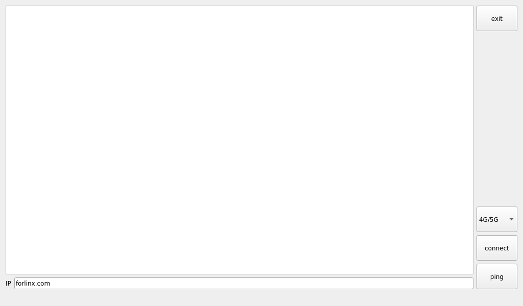
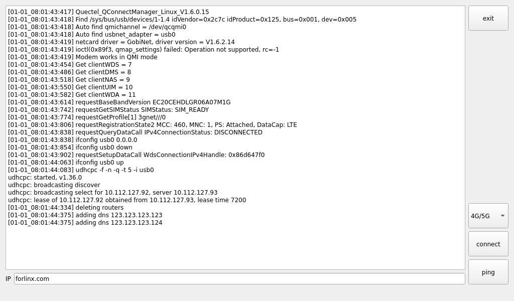
Click the connect button, and the program will automatically enter the dial-up process and obtain IP settings, DNS, etc.
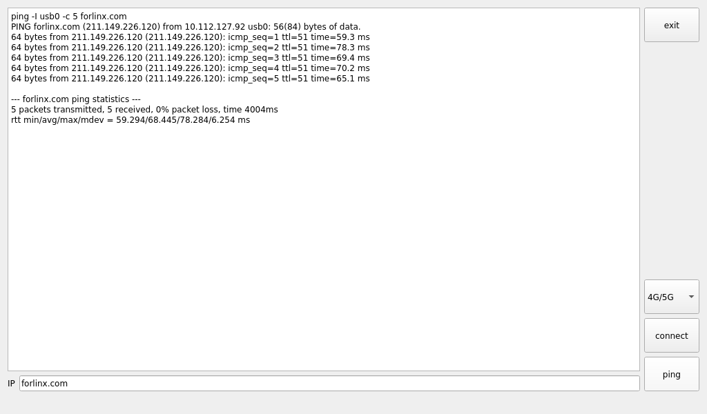
Click the ping button to test.
3.1.6 WiFi Test
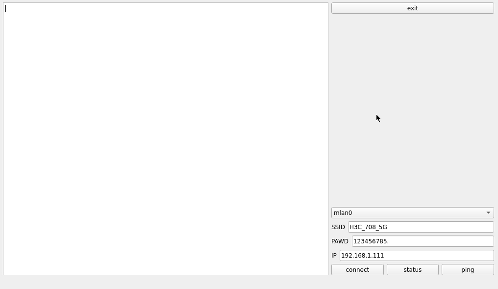
“”WIFI” is a tool for configuring WiFi. The OK- x- UP4 platform comes with the AW-CM358 module onboard by default. The wifi module will exist in the form of mlan node in the system, and this test corresponds to mlan0:
Application Icons
Application Interface
Select mlan0, enter the SSID of the router you wish to connect to in the SSID field, input the router’s password in the PAWD field, and click connect to establish a Wi-Fi connection to the router. Once an IP address is entered in the IP field, click ping to check if the current Wi-Fi network is stable.
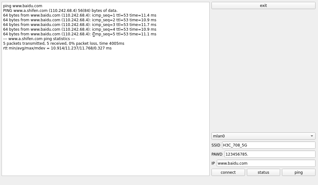
Open the Wifi test application, enter the correct network name and password, and click connect.
After a successful connection, click “ping” to perform a network test.
3.1.7 Network Configuration Test
Upon startup, the eth0 interface on the OK3562J-UP4 is configured by default with a static IP address. You can select between DHCP and static modes via the system’s “Network” configuration application. In static mode, the following network parameters are configurable: IP address, subnet mask, gateway, and DNS servers.

Application Icons
DHCP mode interface is as follows:
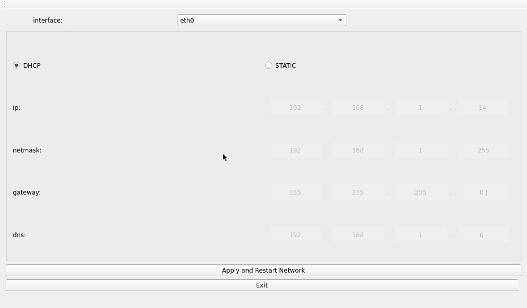
Select DHCP, choose the network card device to be configured in the “interface” section, and click “Apply and Restart Network” at the bottom of the interface to automatically restart the network and obtain an IP address.
Static Mode Configuration Interface:
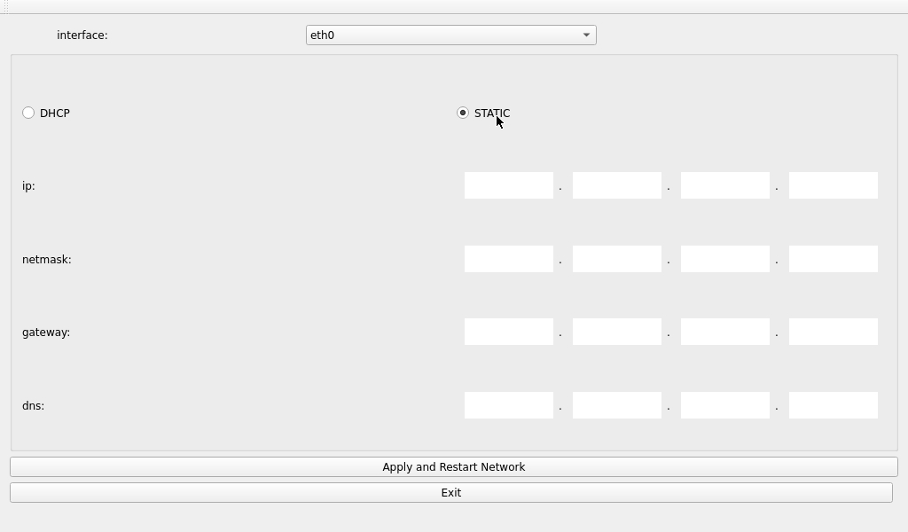
Select the network card device to be configured in the Interface. Enter the desired IP address in the IP field. Enter the subnet mask in the Netmask field. Enter the gateway address in the Gateway field. Enter the DNS server address , in the Gateway field, .
Note: The IP and other information configured in static mode will be saved in the system’s relevant configuration files, so the network settings will persist after each reboot. However, the network information configured in DHCP mode does not need to be considered, as an IP address will be dynamically assigned each time the system restarts.
3.1.8 Ping Test
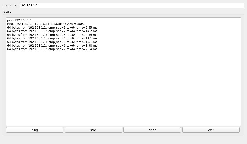
“Ping” is a GUI version of the commonly used network testing command ping:

In the hostname field, write the target IP to ping. After clicking the “ping” button, the result field will show the ping result. Click stop to stop the ping test, and click “clear” to clear the information in result.
3.1.9 Browser Test
“SimpleBrowser” is a straightforward and practical web browser. Please ensure the network connection is stable when using it. Accessing external websites requires DNS to be functional. Upon launch, the browser will default to the official website of Forlinx Embedded.
Note: If the development board’s time is abnormal, it may cause certificate issues. After using the browser, avoid turning off the power immediately. If you need to turn off the power, run the sync command in the command line first, otherwise, the browser may crash and fail to operate properly, requiring a re-flash to resolve the issue.
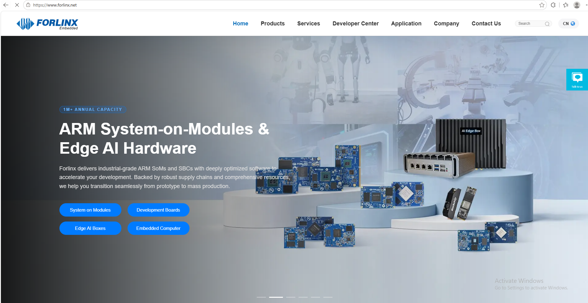
To exit the browser, use the navigation bar: File -> Quit.
3.1.10 Watchdog Test
“WatchDog” is an application used to test the proper functioning of the watchdog:

Application Icons
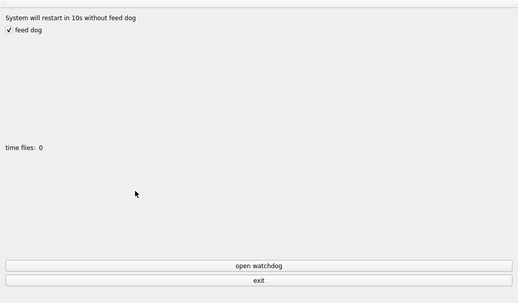
Application Interface
Check the “feed dog” option and click the “open watchdog” button. This will activate the watchdog function, and the program will continue to feed the dog. Normally, the system should not restart during this time.
If you uncheck the “feed dog” option and then click the “open watchdog” button, the watchdog function will still be activated, but the program will not feed the dog. After activating the watchdog for about 10 seconds, the system will restart, indicating that the watchdog function is working properly.
3.1.11 Key Test
“Keypad” is used to test the platform built-in keys:
Application Icons
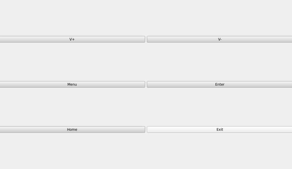
Application Interface
OK3562J-UP4 platform configures 5 physical keys V +, V-, MENU, ENTER and HOME as volume + key, volume- key, menu, enter key and Home respectively by default. When a key is pressed, the corresponding button in the test application will turn blue, indicating that the key function is working properly.
Press Exit to exit the current test and return to the system desktop.
3.1.12 RTC Test
The “RTC” application allows you to view and set the current system time:

Application Icons
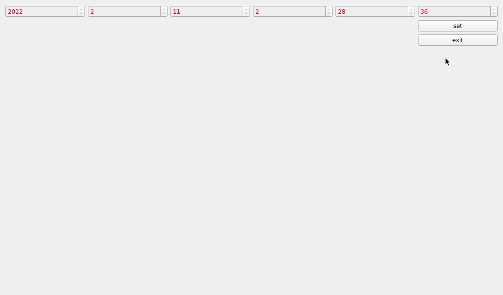
Application Interface
Click “Set” to configure the time, then click “Save” to apply the changes.
With the RTC backup battery installed, you can reboot the development board to confirm that the RTC clock has been successfully set.
3.1.13 Camera Testing
Click the desktop icon to open the Camera. This test application supports both USB cameras and the OV13855 OV5645 camera. Insert a USB camera, such as the RMONCAM 720P.
Note: The camera must be connected before opening the application.
Application Icons
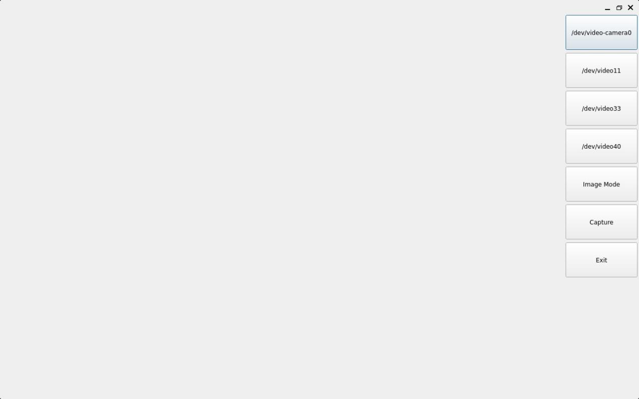
Once the application is opened, click UVC Camera to start the camera preview.
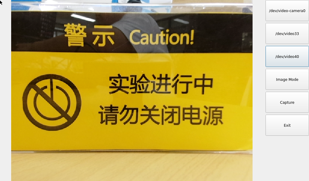
In Video Mode, click the record button to begin recording. To stop recording, click the recording button. The generated video file will be saved at /userdata/VIDEO0.MOV.
Playback testing can be done using the command: gst-play-1.0 /userdata/VIDEO0.mov.
Click the Video Mode button to switch to photo mode, then click Capture to take a photo.
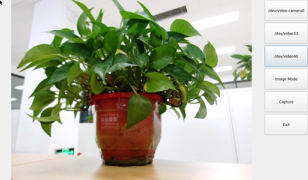
The generated file is located at /userdata/PIC0.jpg

3.1.14 UART Test
Application Icons
In this test, a serial loopback test was carried out by short-circuiting the UART_B pin on the development board. Before testing, the UART3 transmit and receive pins must be short-circuited.
Click the UART test icon to enter the following interface for serial port parameter configuration;
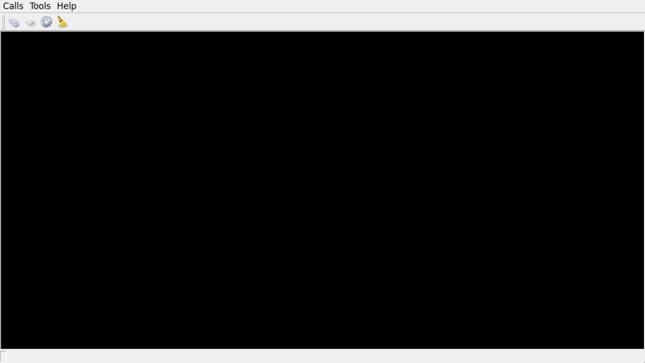
Click the settings button in the upper left corner and set the serial port parameters to be consistent with the computer-side serial port tool parameters, as shown below:
Relevant Parameter |
Meaning |
|---|---|
Select Serial Port |
Configure the serial port (select UART3, i.e. ttyS3) |
BaudRate |
Set baud rate (115200) |
Data bits |
Set data bits (8 bits) |
Parity |
Set parity bit (no parity) |
Stop bits |
Set stop bits (1 bit) |
Flow control |
Set flow control (no flow control) |
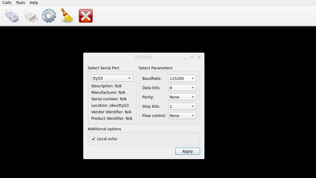
After setting the serial port parameters, click the connect button in the upper left corner. At this point, the test program can perform data transmission and receiving tests;
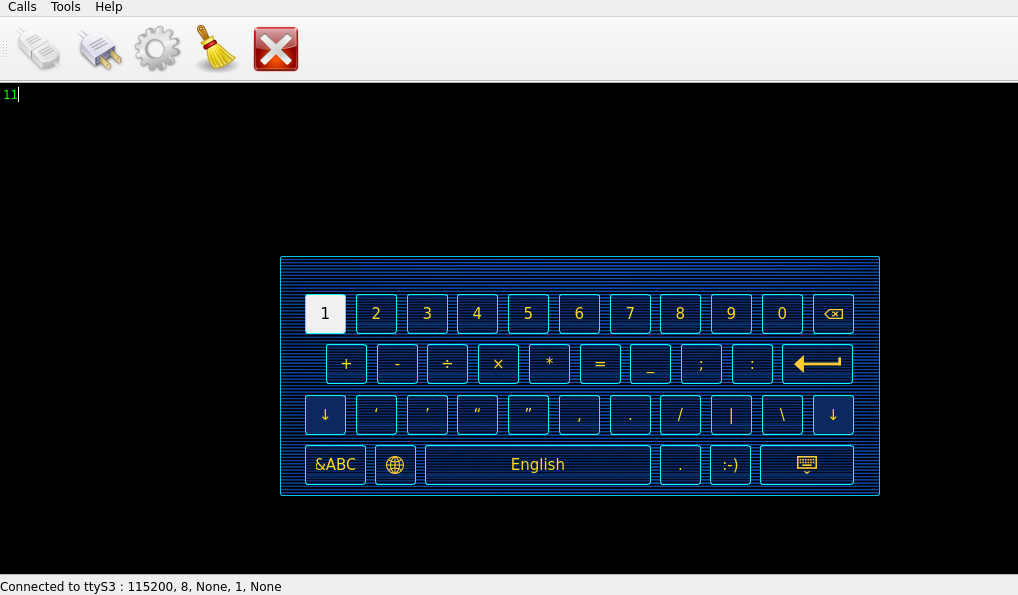
Click the “1” to automatically send the signal. Due to the shorting, the received “1” will also be displayed on the terminal.
3.1.15 Data Test
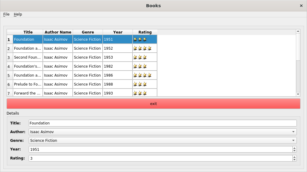
Click the desktop icon to use the SQLite test database.
Application Icons
3.1.16 Backlight Test
“BackLight” is the application for adjusting LCD backligh

Application Icons
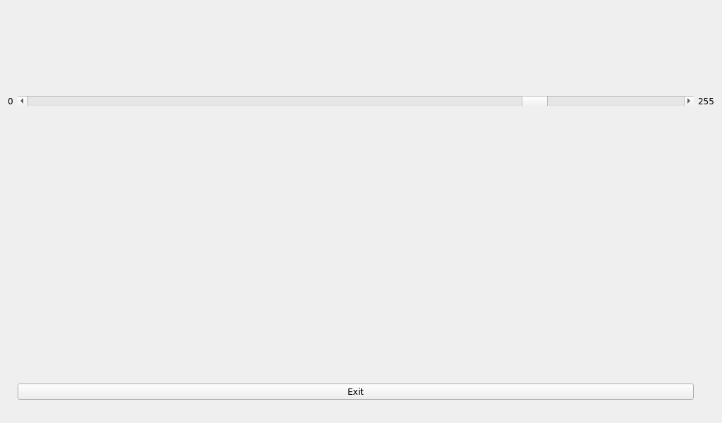
Slide the bar in the interface to set the LCD backlight brightness. Level 0 represents the lowest brightness, and level 255 represents the highest brightness.
Note: This test application limits the minimum brightness level to 1 in the QT interface. To completely turn off the backlight, refer to Section 3.2.20 LCD Backlight Adjustment, and set the brightness value to 0.
3.1.17 Uboot Menu
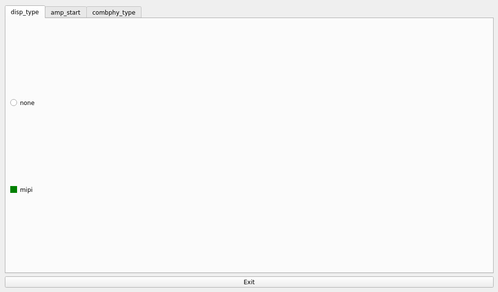
Click the desktop icon to launch the Uboot menu configuration tool.
disp_type Tab: Select the display screen.
None: Do not turn on the screen display
Mipi: enable mipi 1024 * 600 screen display
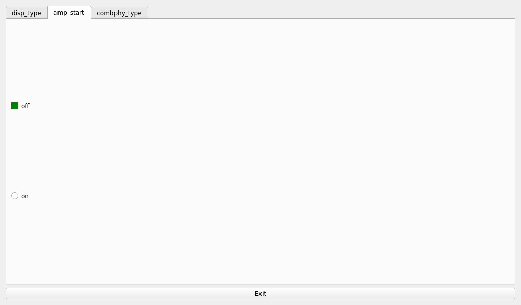
amp_start Tab: Choose whether to enable the audio amplifier (AMP).
off

on
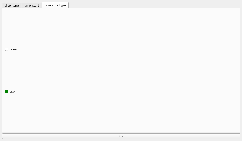
combphy_type Tab: Configure the multiplexing function for USB and PCIe.
None: Turn off combphy
USB: combphy multiplexing as USB function
Configuration changes are saved automatically. A board restart is required for the new settings to take effect.
3.1.18 Web Service
The OK3562J-UP4 development board comes pre-installed with the Lighttpd web server, and the service is automatically started upon system boot. To access the web pages hosted on the board’s webserver, simply enter the board’s IP address in a web browser on your PC.
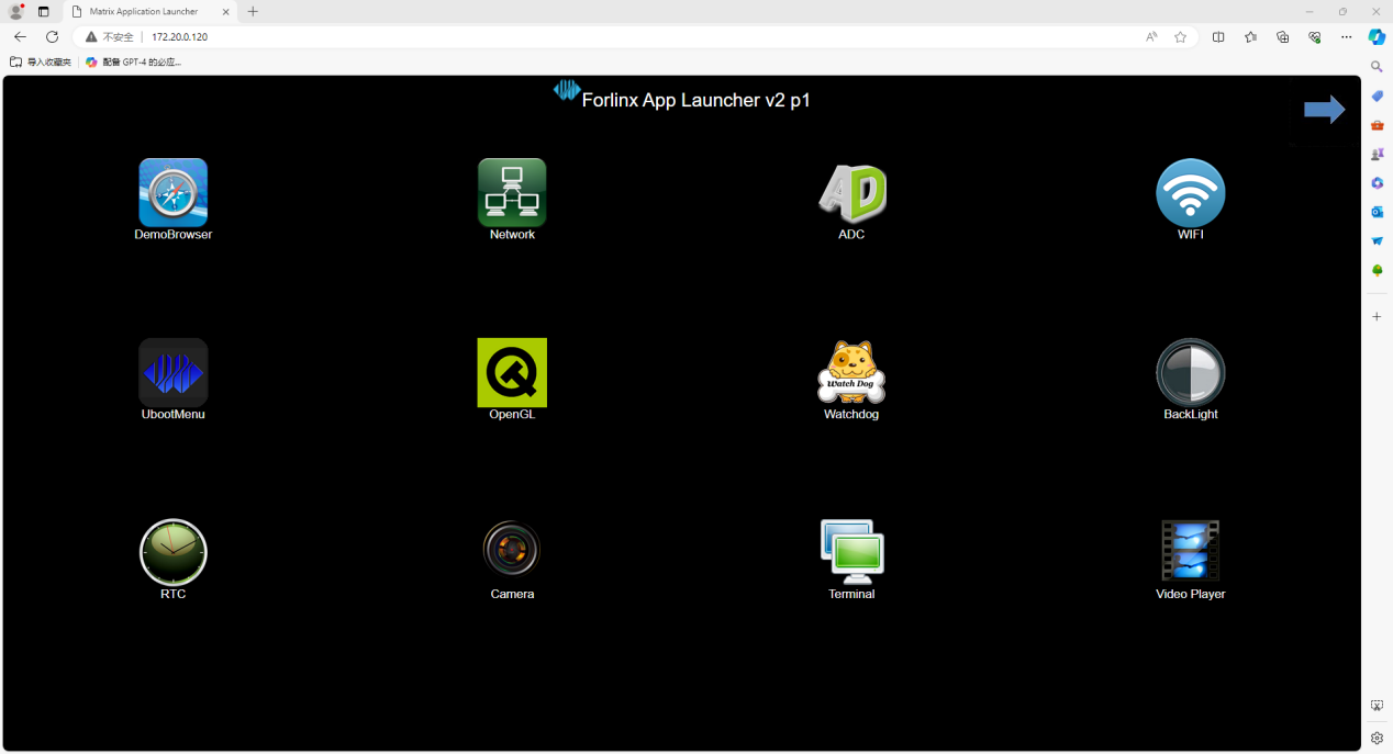
Note: The development board network IP must be in the same subnet as the PC network IP, or the PC must be in the same network subnet as the development board.
3.1.19 ADC Test
The OK3562J-UP4 board provides 13 x ADC, each connectable to a variable resistor.
The channel mappings are as follows:
GPADC_A corresponds to saradc0_in2
GPADC_B corresponds to saradc0_in3
GPADC_C corresponds to saradc0_in4
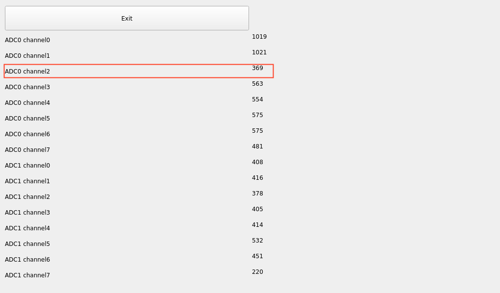
For this test, select saradc0_in2. Apply the input voltage to Pin 1 of connector P34, as shown in the ADC pin hardware diagram below. The chip uses a 1.8V reference voltage, corresponding to a maximum digital value of 1024 for its 10-bit ADC.
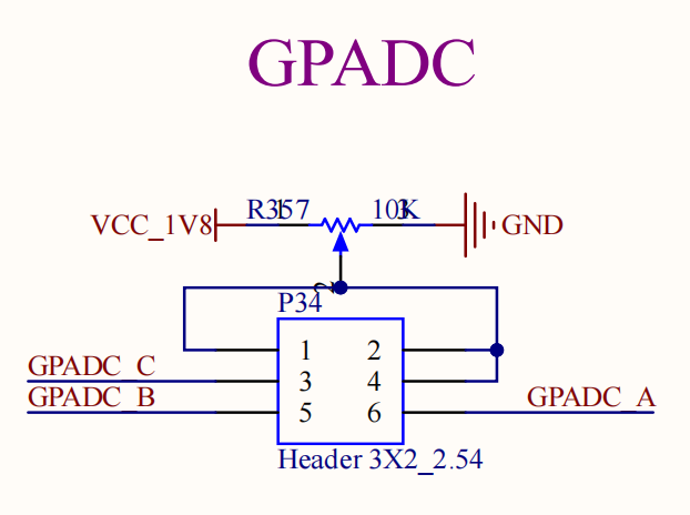
Run the QT ADC application to view the test results.
3.1.20 TFTP System Upgrade
Note:
The current version does not support upgrading MiniLoaderAll.bin via this method;
The transfer uses TFTP over UDP on port 69;
Install the TFTP server tool: Tftpd64.4.64.exe;
Path: OK3562-UP4 User Materials/Tools/Tftpd64.4.64.exe.
Install and run Tftpd64.4.64.exe;
Turn on Tftpd64.4.64.exe to test.
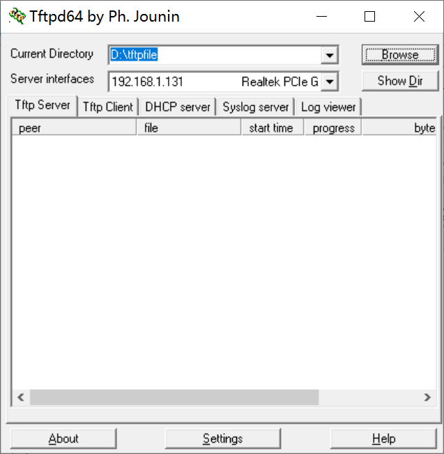
CurrentDirectory: Set to the path containing the OK-x-UP4 partition firmware files.
Server interfaces: Select your PC’s local IP address.
Note: Temporarily disable the Windows Firewall for testing. Users should verify TFTP file download functionality independently.
Open the desktop “Tftp Update” icon on the development board.
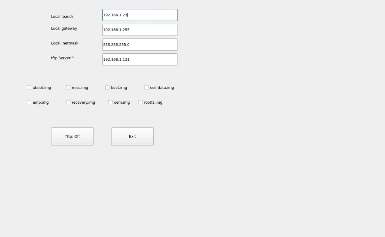
Fill in the configuration fields according to your actual setup and select the firmware to be updated.
Click “Tftp:Off” to change it to “Tftp:On”, then restart the board.
Serial Port Print information as follows:
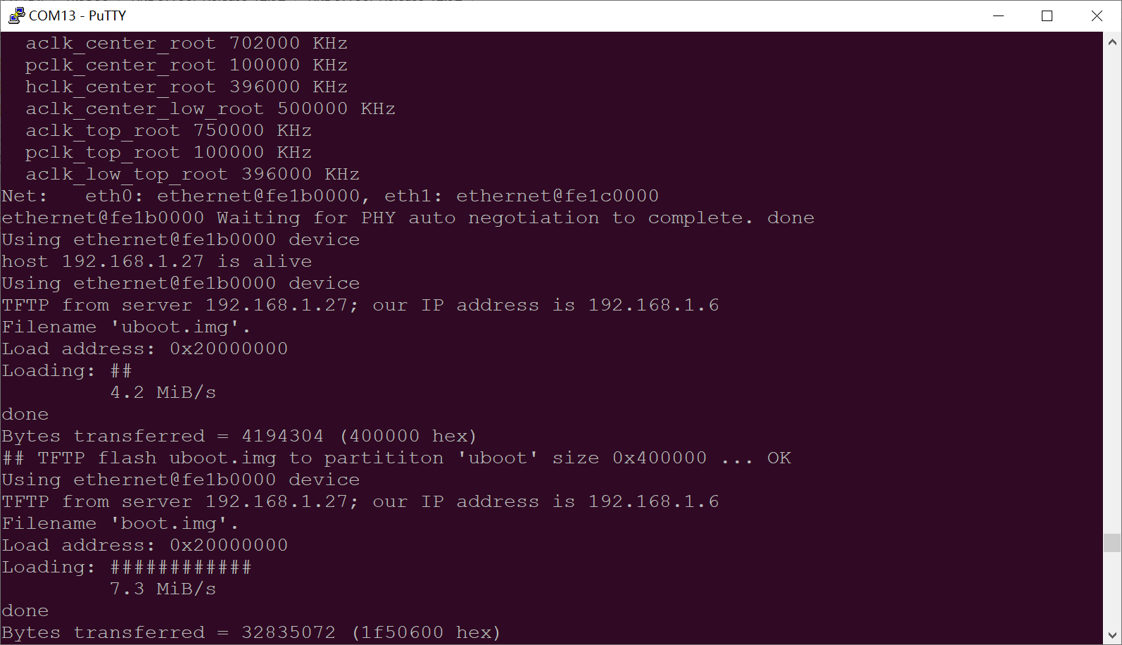
3.1.21 CPU Frequency Configuration Test
Note: The current configuration interface only controls the A53 cores.
Click the desktop icon to access the submenu:
 ->
->
Application Icons
The OK3562J-UP4 CPU clock is up to 2.0 GHz. By default, the CPU will dynamically adjust the clock speed according to the load, but a fixed CPU clock speed can also be set.
Click the desktop Power icon to enter the CPU frequency settings page:
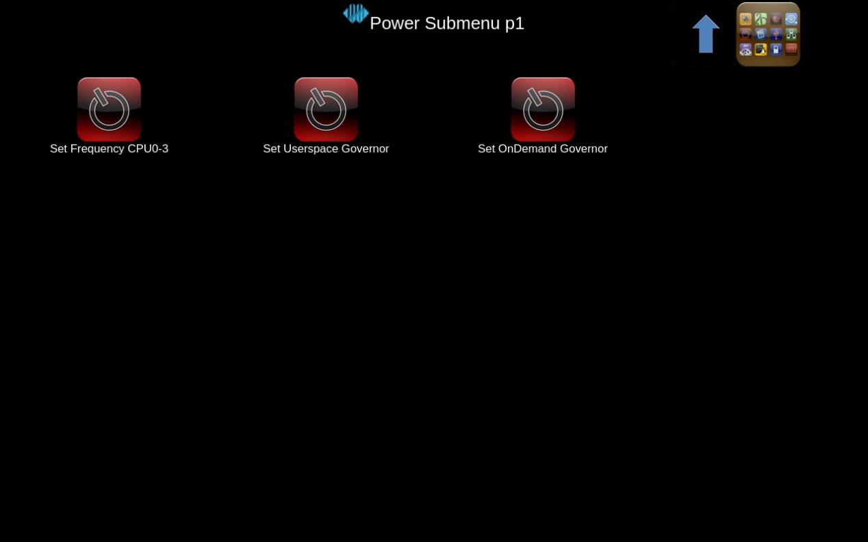
Set Userspace Governor:Set the main clock in user space.
Set FrequencyCPU0-3:Set the main clock.
Take setting the main frequency as an example. If you need to set a fixed frequency, first click Set Userspace Governor, then click Run. Afterward, return to the interface shown above and click Set Frequency CPU0-3 to configure the desired frequency.
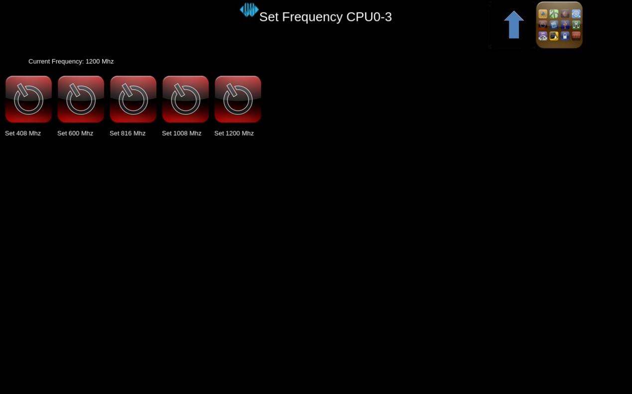
Select the corresponding frequency according to needs for setting.
3.1.22 Recording Test
Icon:
Connect the microphone to the MIC jack.
Click the icon to open the test application and confirm the recording function is working properly.
Select a save location for the recording, then click “Start” to begin and “Stop” to end.
Click the “Input Device” radio button to select “alsa:sysdefault:CARD=rockchiprk809”, then click the “Channels” radio button to select “2”. The interface is shown below:
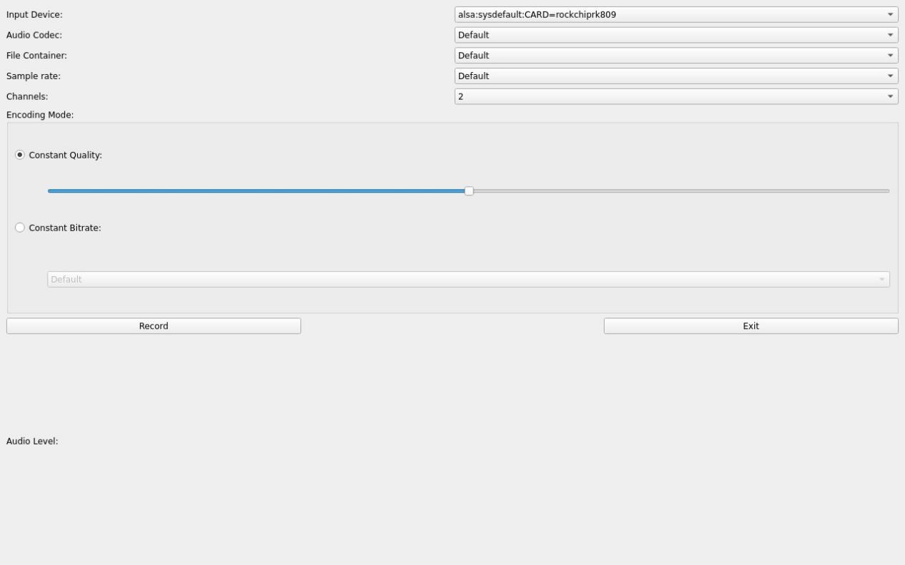
Click the Record button to start the test. The audio file is saved to the root directory as /clip_XXXX.avi.
3.1.23 SPI Test
Icon:
Click the icon to enter the SPI test interface. Short the SPI2_MOSI_M0 and SPI2_MISO_M0 pins, click send below, and you can receive the sent data to complete the test.
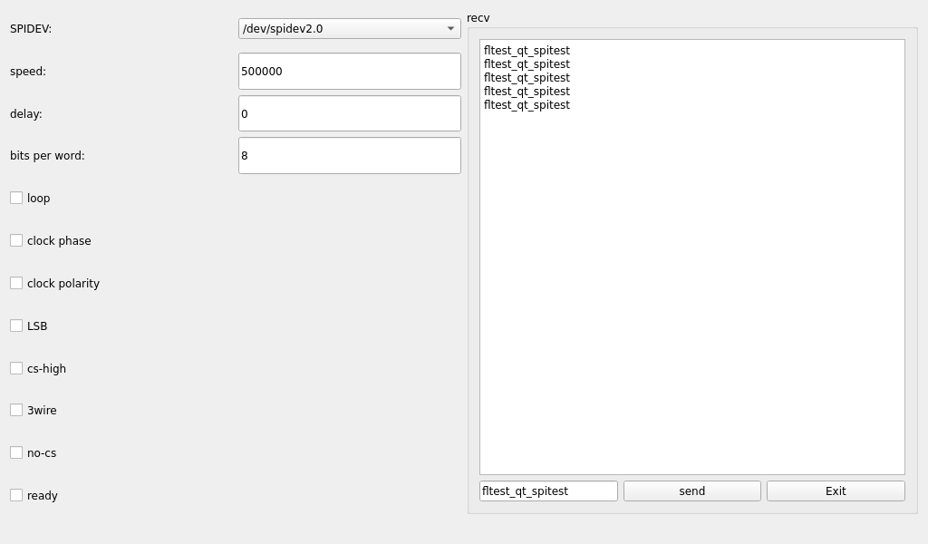
4. OK3562J-UP4 Command Line Function Test
4.1 Command Line Function Testing
The OK3562-UP4 platform comes with a rich set of command-line tools for users to utilize.
4.1.1 System Information Query
View kernel information:
root@OK-x-UP4:/# uname -a
Linux OK-x-UP4 5.10.198 #1 SMP Mon Jul 14 19:23:20 CST 2025 aarch64 GNU/Linux
To view environment variable information:
root@OK-x-UP4:/# env | sort
ADBD_SHELL=/bin/bash
AUTOAUDIOSINK_PREFERRED=pulsesink
CHROMIUM_FLAGS=--enable-wayland-ime
DBUS_SESSION_BUS_ADDRESS=unix:path=/var/run/dbus/system_bus_socket
EDITOR=/bin/vi
GST_DEBUG_NO_COLOR=1
GST_INSPECT_NO_COLORS=1
GST_V4L2SRC_DEFAULT_DEVICE=/dev/video-camera0
GST_V4L2SRC_MAX_RESOLUTION=3840x2160
GST_V4L2SRC_RK_DEVICES=_mainpath:_selfpath:_bypass:_scale
GST_V4L2_PREFERRED_FOURCC=NV12:YU12:NV16:YUY2
GST_V4L2_USE_LIBV4L2=1
GST_VIDEO_CONVERT_PREFERRED_FORMAT=NV12:NV16:I420:YUY2
GST_VIDEO_CONVERT_USE_RGA=1
GST_VIDEO_DECODER_QOS=0
GST_VIDEO_FLIP_USE_RGA=1
HOME=/
LANG=en_US.UTF-8
PATH=/usr/bin:/usr/sbin
PIXMAN_USE_RGA=1
PLAYBIN2_PREFERRED_AUDIOSINK=pulsesink
PULSE_HOME=/userdata/.pulse
PWD=/
QT_QPA_FONTDIR=/usr/share/fonts
QT_QPA_PLATFORM=wayland-egl
QT_QPA_PLATFORM_PLUGIN_PATH=/usr/lib/qt/plugins
RUNLEVEL=#x-07/14/2025
SHELL=/bin/sh
SHLVL=0
TERM=vt102
UMS_FILE=/userdata/ums_shared.img
UMS_FSTYPE=vfat
UMS_MOUNT=0
UMS_MOUNTPOINT=/mnt/ums
UMS_RO=0
UMS_SIZE=256M
USB_FUNCS=adb
USER=root
WAYLANDSINK_FORCE_DMABUF=1
WESTON_DISABLE_ATOMIC=1
WESTON_DRM_KEEP_RATIO=1
WESTON_DRM_MIN_BUFFERS=2
WESTON_DRM_MIRROR=1
WESTON_FREEZE_DISPLAY=/tmp/.freeze_weston
WL_OUTPUT_VERSION=3
XDG_RUNTIME_DIR=/var/run
_=/usr/bin/env
storagemedia=emmc
4.1.2 Frequency Scaling Test
Note: The four A53 cores are designated as cpu0, cpu1, cpu2 and cpu3. Note: This process uses CPU0 as an example. In actual process, CPU1, CPU2, and CPU3 will be adjusted simultaneously.
All cpufreq governor types supported in the current kernel:
root@OK-x-UP4:/# cat /sys/devices/system/cpu/cpu0/cpufreq/scaling_available_governors
interactive conservative ondemand userspace powersave performance schedutil
userspace indicates user mode, in which user programs are allowed to adjust the CPU frequency.
To view the current frequency levels supported by the CPU:
root@OK-x-UP4:/# cat /sys/devices/system/cpu/cpu0/cpufreq/scaling_available_frequencies
408000 600000 816000 1008000 1200000
Set to user mode and modify the frequency to 1200000:
root@OK-x-UP4:/# echo userspace > /sys/devices/system/cpu/cpu0/cpufreq/scaling_governor
root@OK-x-UP4:/# echo 1200000 > /sys/devices/system/cpu/cpu0/cpufreq/scaling_setspeed
To view the current frequency after modification:
root@OK-x-UP4:/# cat /sys/devices/system/cpu/cpu0/cpufreq/cpuinfo_cur_freq
1200000
4.1.3 Temperature Test
To view temperature values:
root@OK-x-UP4:/# cat /sys/class/thermal/thermal_zone0/temp
39018
The temperature value is 39.0℃.
4.1.4 DDR Test
root@OK-x-UP4:/# fltest_memory_bandwidth.sh
L1 cache bandwidth rd test with # process
0.008192 9321.88
0.008192 9319.16
0.008192 9161.18
0.008192 9151.21
0.008192 9320.87
L2 cache bandwidth rd test
0.131072 7404.49
0.131072 7419.17
0.131072 7518.43
0.131072 7505.30
0.131072 7503.54
Main mem bandwidth rd test
52.43 2912.71
52.43 2911.42
52.43 2888.16
52.43 2892.46
52.43 2908.67
L1 cache bandwidth wr test with # process
0.008192 14809.07
0.008192 14810.04
0.008192 14810.04
0.008192 14795.62
0.008192 14811.39
L2 cache bandwidth wr test
0.131072 8360.66
0.131072 8566.63
0.131072 8510.54
0.131072 8432.43
0.131072 8571.47
Main mem bandwidth wr test
52.43 1822.34
52.43 1824.56
52.43 1799.20
52.43 1805.52
52.43 1818.93
The LPDDR4 write bandwidth is approximately 1818M/s, and the read bandwidth is approximately 2912M/s.
4.1.5 Watchdog Test
Watchdog is a commonly used function in embedded systems. The device node for the watchdog in OK3562-UP4 is /dev/
Start the watchdog, set the reset timeout to 10 seconds, and feed the watchdog periodically so that the system will not restart.
root@OK-x-UP4:/# fltest_watchdog -t 10 -c
Watchdog Ticking Away!
When using Ctrl+C to end the test program, feeding stops, and the watchdog remains open. After 10s, the system resets.
If you do not want a reset enter the command to close the watchdog within 10s after ending the program:
root@OK-x-UP4:/# fltest_watchdog -d
Start the watchdog, set the reset timeout to 10 seconds, but do not feed it; the system will reboot after 10 seconds.
root@OK-x-UP4:/# fltest_watchdog -t 10
[   88.241842] watchdog: watchdog0: watchdog did not stop!
Watchdog Ticking Away!
4.1.6 RTC Function Test
Note: Ensure that a button battery is installed on the board and the battery voltage is normal…
To perform the RTC test, the date and hwclock tools are used to set the system and hardware clocks. The device is then powered off and on to confirm that the system clock successfully synchronizes with the RTC upon reboot.
Time Settings:
root@OK-x-UP4:/# date -s "2022-12-12 17:23:00"      //Set the system (software) time
Mon Dec 12 17:23:00 CST 2022
root@OK-x-UP4:/# hwclock -w					   						  //Synchronize the system time to the hardware (RTC) clock
root@OK-x-UP4:/# hwclock -r					    						//Display the hardware clock time
Mon Dec 12 17:23:06 CST 2022
Then power off and power on the board. After entering the system, read the system time, and you can see that the time is synchronized.
root@OK-x-UP4:/# date
Mon Dec 12 17:23:20 CST 2022
4.1.7 Key Test
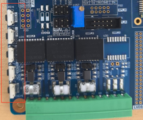
Use the fltest_keytest command-line tool to test the keys. Currently, fltest_keytest supports testing the five keys on the carrier board: VOL+, VOL-, MENU and ENTER, HOME, with key codes, 115, 114, 139, 158 and 102 respectively.
Execute the following command. Please note that if a touchscreen is present, use ‘event3’:
root@OK-x-UP4:~# fltest_keytest /dev/input/event3
When the keys are pressed and released in sequence, the terminal will d isplay the following output:
key115 Presse                                                         // VOL+Presse
key115 Released                                                       // VOL+Released
key114 Presse                                                         // VOL-Presse
key114 Released                                                       // VOL-Released
key139 Presse                                                         // MENU Presse
key139 Released                                                       // MENU Released
key158 Presse                                                         // ENTER Presse
key158 Released                                                       // ENTER Released
key102 Presse                                                         // HOME Presse
key102 Released                                                       // HOME Released
4.1.8 UART Test
According to the OK3562-UP4 carrier board schematic, a total of four (4) UART ports are exposed for external connection: UART0, UART3, UART5, and UART8. Their functional assignments are as follows:
UART0: Designated as the Debug/Console UART.
UART8: Dedicated as the Bluetooth UART.
UART3 & UART5: Function as general-purpose Serial/UART ports. Supports baud rates of up to 4M.
UART |
Device Nodes |
Description |
|---|---|---|
UART3 |
/dev/ttyS3 |
TTL level |
UART8 |
/dev/ttyS8 |
Used for Bluetooth, not led out separately, cannot be used directly for this test. |
UART5 |
/dev/ttyS5 |
RS485 |
Taking the UART3 serial port as an example, short-circuit the UART3 transmit and receive pins—which correspond to PIN2 and PIN4 respectively—in accordance with the development board’s schematic diagram.
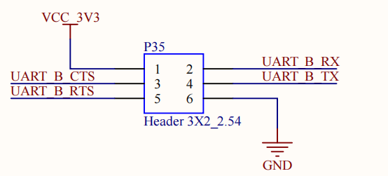
Enter the following command in the development board serial port:
root@OK-x-UP4:/# fltest_uarttest -d /dev/ttyS3 -b 115200 -r &
[1] 17948
root@OK-x-UP4:/# fltest_uarttest -d /dev/ttyS3 -b 115200 -w
tx_0: dYalODr7wVnRsPHLlktSduGxsP8fqlAR
rx_0: dYalODr7wVnRsPHLlktSduGxsP8fqlAR
[1]+  Done                    fltest_uarttest -d /dev/ttyS3 -b 115200 -r
4.1.9 ADC Test
The OK3562-UP4 development board features 13 x ADC internally, with one adjustable resistor connectable to each channel. Select “saradc0_in2” for testing. The hardware diagram of the ADC pins is shown below; apply the input voltage to pin 1 of P34. The chip uses a 1.8V reference voltage, corresponding to a maximum digital value of 1024 for its 10-bit ADC.
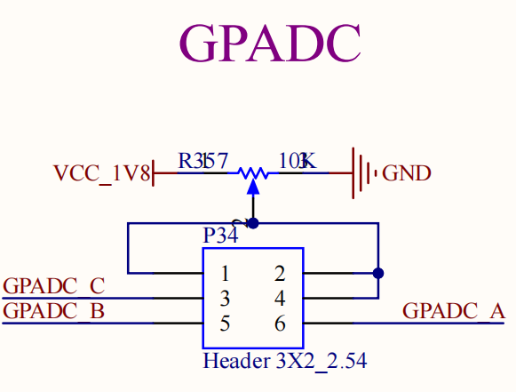
The following section uses the SARADC_VIN2 as an example to test the values of adjustable resistors:
root@OK-x-UP4:~# cd /sys/bus/iio/devices/iio:device0
root@OK-x-UP4:/sys/bus/iio/devices/iio:device0# cat in_voltage2_raw
809
4.1.10 TF Card Test
Note: The SD card is mounted at /run/media/ and supports hot-swapping.
Before powering on, insert the TF card into the TF card slot on the carrier board. Power on the board, run the command “dmesg”, and the following information will be displayed in the terminal:
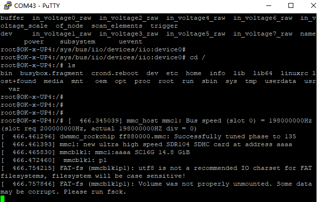
Check the mount directory:
root@OK-x-UP4:/# mount | grep "mmcblk1"
/dev/mmcblk1p1 on /run/media/mmcblk1p1 type vfat (rw,relatime,gid=6,fmask=0007,dmask=0007,allow_utime=0020,codepage=936,iocharset=utf8,shortname=mixed,errors=remount-ro)
Write test:
root@OK-x-UP4:/# dd if=/dev/zero of=/run/media/mmcblk1p1/test bs=1M count=500 conv=fsync
500+0 records in
500+0 records out
524288000 bytes (524 MB, 500 MiB) copied, 26.7012 s, 19.6 MB/s
Read test:
Note: To ensure the accuracy of the data, please restart the development board to test the reading speed.
root@OK-x-UP4:/# dd if=/run/media/mmcblk1p1/test of=/dev/null bs=1M count=500
500+0 records in
500+0 records out
524288000 bytes (524 MB, 500 MiB) copied, 6.26221 s, 83.7 MB/s
After using the TF card, you need to use umount to unmount the TF card before ejecting it.
root@OK-x-UP4:~# umount /run/media/mmcblk1p1
Note: Exit the TF card mount path before removing the TF card.
4.1.11 eMMC Test
The eMMC on the OK3562-UP4 platform operates by default in HS200 mode at a clock speed of 200 MHz. Below is a brief test of the eMMC’s read and write speeds, using the ext4 file system as an example.
Write test:
root@OK-x-UP4:/# dd if=/dev/zero of=/test bs=1M count=500 conv=fsync
500+0 records in
500+0 records out
524288000 bytes (524 MB, 500 MiB) copied, 5.05609 s, 104 MB/s
Read test:
Note: To ensure the accuracy of the data, please restart the development board to test the reading speed.
root@OK-x-UP4:/# dd if=/test of=/dev/null bs=1M iflag=direct
500+0 records in
500+0 records out
524288000 bytes (524 MB, 500 MiB) copied, 2.4392 s, 215 MB/s
4.1.12 USB Mouse Test
Connect a USB mouse to the USB port on the OK3562-UP4 platform and use the “dmesg” command; the output on the serial terminal is as follows:
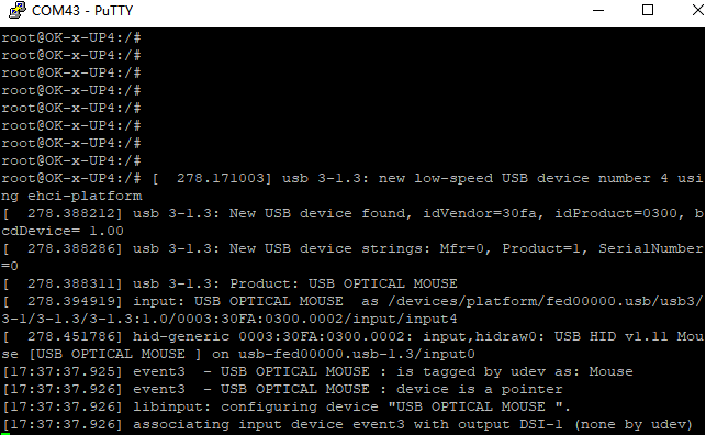
An arrow cursor will appear on the screen, indicating that the mouse is functioning properly.
4.1.13 USB2.0
OK3562-UP4 supports 1 x USB 2.0 interface. Please connect USB devices such as mice, keyboards, and flash drives to any onboard USB HOST port, with full hot-plug support for these devices. Here, mounting a USB flash drive is used as an example. USB flash drive testing has currently been verified up to 32 GB; capacities above 32 GB have not been tested.
The terminal will print information about the USB drive. Since there are various USB drives, the displayed information may vary.
After the development board boots, connect a USB flash drive to the board USB HOST interface. Since the default log level is relatively low, no message may be printed directly; You can use the dmesg command to view messages and locate the USB-drive-related information.
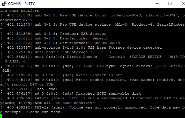
View the mount directory:
root@OK-x-UP4:/# mount | grep "sda1"
/dev/sda1 on /run/media/sda1 type vfat (rw,relatime,gid=6,fmask=0007,dmask=0007,allow_utime=0020,codepage=936,iocharset=utf8,shortname=mixed,errors=remount-ro)
You can see that /run/media/sda1 is the mount path for the USB storage device
Check the contents of the USB drive (here, sda1 should match the actual partition name of the USB drive).
root@OK-x-UP4:~# ls -l /run/media/sda1/
total 8
drwxrwx--- 2 root disk 8192 Sep 23  2021 'System Volume Information'
-rwxrwx--- 1 root disk    0 Apr 25 09:25  test
Write test (write speed is limited by the specific storage device):
root@OK-x-UP4:/# dd if=/dev/zero of=/run/media/sda1/test bs=1M count=500 conv=fsync
500+0 records in
500+0 records out
524288000 bytes (524 MB, 500 MiB) copied, 27.3353 s, 19.2 MB/s
Read test:
Note: To ensure the accuracy of the data, please restart the development board to test the reading speed.
root@OK-x-UP4:/# dd if=/run/media/sda1/test of=/dev/null bs=1M iflag=direct
500+0 records in
500+0 records out
524288000 bytes (524 MB, 500 MiB) copied, 20.2133 s, 25.9 MB/s
After using the USB drive, use umount to unmount it before unplugging:
root@OK-x-UP4:~# umount /run/media/sda1
Note: Exit the mount path before unplugging the USB drive.
4.1.14 USB to Quad Serial Port Test
Note:
Supports XR21V1414 USB to serial port chip driver;
The USB to four-serial-port adapter is an optional module. If you require it, please contact Forlinx Embedded sales personnel.
After the development board powers on, connect the USB to quad serial port module via the USB HOST interface. The terminal will display the following information:
[  836.286313] usb 1-1.1: new full-speed USB device number 4 using ehci-platform
[  836.502174] usb 1-1.1: New USB device found, idVendor=04e2, idProduct=1414, bcdDevice= 0.03
[  836.502245] usb 1-1.1: New USB device strings: Mfr=0, Product=0, SerialNumber=0
[  836.504546] cdc_xr_usb_serial 1-1.1:1.0: This device cannot do calls on its own. It is not a modem.
[  836.505009] cdc_xr_usb_serial 1-1.1:1.0: ttyXR_USB_SERIAL0: USB XR_USB_SERIAL device
[  836.509062] cdc_xr_usb_serial 1-1.1:1.2: This device cannot do calls on its own. It is not a modem.
[  836.509550] cdc_xr_usb_serial 1-1.1:1.2: ttyXR_USB_SERIAL1: USB XR_USB_SERIAL device
[  836.513236] cdc_xr_usb_serial 1-1.1:1.4: This device cannot do calls on its own. It is not a modem.
[  836.513640] cdc_xr_usb_serial 1-1.1:1.4: ttyXR_USB_SERIAL2: USB XR_USB_SERIAL device
[  836.517896] cdc_xr_usb_serial 1-1.1:1.6: This device cannot do calls on its own. It is not a modem.
[  836.518322] cdc_xr_usb_serial 1-1.1:1.6: ttyXR_USB_SERIAL3: USB XR_USB_SERIAL device
Check the status of USB devices using lsusb:
root@OK-x-UP4:/# lsusb
Bus 001 Device 001: ID 1d6b:0002
Bus 001 Device 002: ID 1a40:0101
Bus 002 Device 001: ID 1d6b:0001
Bus 001 Device 004: ID 04e2:1414                             //The vid and pid of the conversion chip
Check whether serial device nodes have been created under /dev:
root@OK-x-UP4:/# ls /dev/ ttyXRUSB*
/dev/ttyXRUSB0  /dev/ttyXRUSB1  /dev/ttyXRUSB2  /dev/ttyXRUSB3
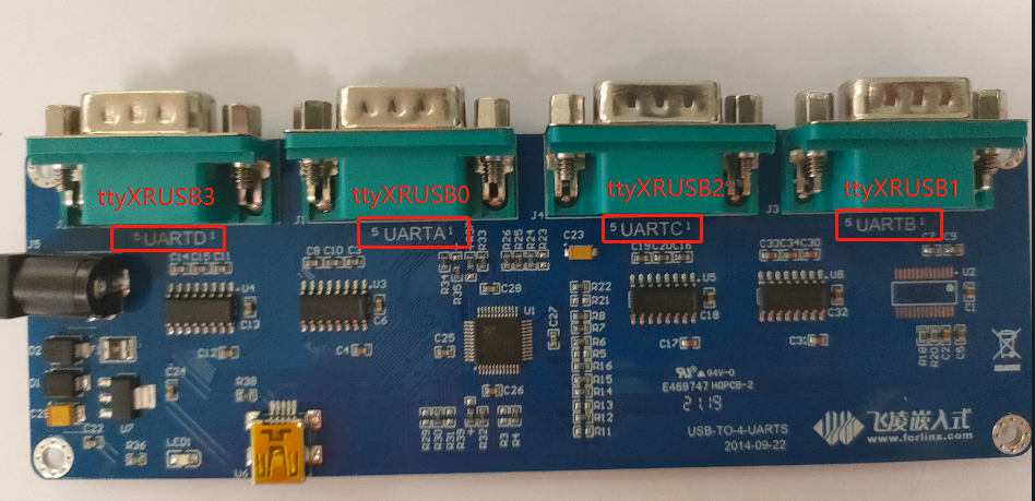
The correspondence between the four extended serial ports and the device nodes is shown in the following figure:
For the test method, refer to Section 3.2.8 UART Test.
4.1.15 USB3.0/ USB OTG Test
The USB3.0 / USB OTG and PCIE functions on the OK3562-UP4 are multiplexed on the same physical interface. The functional specifications are as follows:
USB3.0: Supports Host mode only.
USB OTG: Supports USB2.0 only.
To test the USB functionalities (including USB3.0 and USB OTG), the following hardware and bootloader configuration is required:
Set the carrier board DIP switch S3 to the OFF position.
In the Uboot menu, set the combphy_type parameter to usb (Refer to Section 4.2.29 Uboot Menu).
USB Host Mode: For connecting standard USB peripherals (e.g., flash drives, keyboard, mouse).
USB Device Mode: Used for system flashing, ADB file transfer, and debugging.
4.1.15.1 USB3.0 Host Mode
Set the carrier board DIP switch S2 to the ON position;
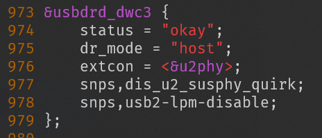
Edit the device tree file “arch/arm64/boot/dts/rockchip/OK-x-UP4-common.dtsi” (this is the default setting in the factory image, so no changes are required) and set the “dr_mode” attribute of the “usbdrd_dwc3” node to “host”, as shown in the figure below:
Recompile the kernel image and flash it to the development board;
Set the carrier board DIP switch S3 to OFF;
In the Uboot menu, set combphy_type to usb;
Connect a USB 3.0 flash drive to the board’s USB3.0 Type-A port (labeled P19). The drive should be detected.
root@OK-x-UP4:/# [ 1885.467547] usb 2-1: new SuperSpeed Gen 1 USB device number 3 using xhci-hcd
[ 1885.490021] usb 2-1: New USB device found, idVendor=0951, idProduct=1666, bcdDevice= 1.10
[ 1885.490089] usb 2-1: New USB device strings: Mfr=1, Product=2, SerialNumber=3
[ 1885.490114] usb 2-1: Product: DataTraveler 3.0
[ 1885.490138] usb 2-1: Manufacturer: Kingston
[ 1885.490159] usb 2-1: SerialNumber: 408D5CBECBBDE7B1E91610B7
[ 1885.492779] usb-storage 2-1:1.0: USB Mass Storage device detected
[ 1885.494936] scsi host0: usb-storage 2-1:1.0
[ 1886.509253] scsi 0:0:0:0: Direct-Access     Kingston DataTraveler 3.0 PMAP PQ: 0 ANSI: 6
[ 1886.512794] sd 0:0:0:0: [sda] 121110528 512-byte logical blocks: (62.0 GB/57.8 GiB)
[ 1886.513503] sd 0:0:0:0: [sda] Write Protect is off
[ 1886.514169] sd 0:0:0:0: [sda] Write cache: disabled, read cache: enabled, doesn't support DPO or FUA
[ 1886.599220]  sda: sda1
[ 1886.605033] sd 0:0:0:0: [sda] Attached SCSI removable disk
Check the mount directory:
root@OK-x-UP4:/# mount | grep "sda"
/dev/sda1 on /run/media/sda1 type vfat (rw,relatime,gid=6,fmask=0007,dmask=0007,allow_utime=0020,codepage=936,iocharset=utf8,shortname=mixed,errors=remount-ro)
You can see that/run/media/SDA is the mount path for the USB storage device.
View the contents of the USB flash disk (the SDA here is subject to the actual partition name of the USB flash disk):
root@OK-x-UP4:~# ls -l /run/media/sda1/
total 1048576
-rwxrwxrwx 1 root root 1073741824 Jan  1  1980 test1g
Write test. Write speed is limited by the specific storage device:
root@OK-x-UP4:/# dd if=/dev/zero of=/run/media/sda1/test bs=1M count=500 conv=fsync
500+0 records in
500+0 records out
524288000 bytes (524 MB, 500 MiB) copied, 20.8983 s, 25.1 MB/s
Read test:
Note: To ensure the accuracy of the data, please restart the development board to test the reading speed.
root@OK-x-UP4:/# dd if=/run/media/sda1/test of=/dev/null bs=1M count=500 iflag=direct
500+0 records in
500+0 records out
524288000 bytes (524 MB, 500 MiB) copied, 3.06048 s, 171 MB/s
After using the USB drive, use umount to unmount it before unplugging:
root@OK-x-UP4:~# umount /run/media/sda1
Note: Exit the mount path before unplugging the USB drive.
4.1.15.2 USB OTG Mode
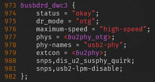
Modify the “usbdrd_dwc3” node in the device tree file “arch/arm64/boot/dts/rockchip/OK-x-UP4-common.dtsi”, as shown in the figure below:
Recompile the kernel image and flash it to the development board;
Set the carrier board DIP switch S3 to OFF.
In the Uboot menu, set combphy_type to usb;
For Host mode, set DIP switch S2 on the development carrier board to the ON position.
At this point, simply plug the USB disk into the P19 USB-A port and it will be recognized; the USB disk will operate at USB 2.0 speed (if it is not automatically recognized, switch S3 to OFF and then back to ON).
Connect the USB flash disk to the USB3.0-A port of the development board (silk-screen P19) to identify the USB flash disk:
[   48.317004] usb 3-1: new high-speed USB device number 3 using xhci-hcd
[   48.460355] usb 3-1: New USB device found, idVendor=05e3, idProduct=0747, bcdDevice= 8.19
[   48.460422] usb 3-1: New USB device strings: Mfr=3, Product=4, SerialNumber=5
[   48.460449] usb 3-1: Product: USB Storage
[   48.460470] usb 3-1: Manufacturer: Generic
[   48.460491] usb 3-1: SerialNumber: 000000000819
[   48.463227] usb-storage 3-1:1.0: USB Mass Storage device detected
[   48.465081] scsi host0: usb-storage 3-1:1.0
[   49.492654] scsi 0:0:0:0: Direct-Access     Generic  STORAGE DEVICE   0819 PQ: 0 ANSI: 6
[   49.940084] sd 0:0:0:0: [sda] 124735488 512-byte logical blocks: (63.9 GB/59.5 GiB)
[   49.941418] sd 0:0:0:0: [sda] Write Protect is off
[   49.942545] sd 0:0:0:0: [sda] Write cache: disabled, read cache: enabled, doesn't support DPO or FUA
[   49.970261] sd 0:0:0:0: [sda] Attached SCSI removable disk
For Device mode, set DIP switch S2 on the carrier board to OFF.
Connect your computer to the P35 USB-C socket on the development board using a USB-A to USB-C cable, then simply restart the development board.
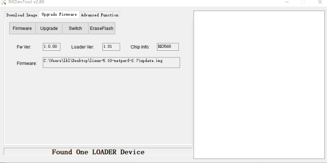
Once the Rockchip development tools display the message “An ADB device is detected”, you can use “adb pull” to download files from the development board to your computer, and “adb push” to upload files from your computer to the development board.
Open the RKDevTool_Release/bin directory in the Windows 10 PowerShell terminal
Windows PowerShell
Copyright (C) Microsoft Corporation. All rights reserved.

Try the new cross-platform PowerShell: https://aka.ms/pscore6

PS C:\Users\Acer> cd D:\rk3562\RKDevTool\RKDevTool_Release\bin
PS D:\rk3562\RKDevTool\RKDevTool_Release\bin> .\adb.exe devices
List of devices attached
38bc17e18f2c57bc        device

PS D:\rk3562\RKDevTool\RKDevTool_Release\bin> .\adb.exe push D:\test.mp3 /home/forlinx/
D:\test.mp3: 1 file pushed. 13.8 MB/s (4818092 bytes in 0.334s)
PS D:\rk3562\RKDevTool\RKDevTool_Release\bin>
PS D:\rk3562\RKDevTool\RKDevTool_Release\bin> .\adb.exe pull /home/forlinx/test
/home/forlinx/test: 1 file pulled. 0.0 MB/s (29 bytes in 0.002s)
PS D:\rk3562\RKDevTool\RKDevTool_Release\bin> ls .\test

    Catalog: D:\rk3562\RKDevTool\RKDevTool_Release\bin

Mode                 LastWriteTime         Length Name
----                 -------------         ------ ----
-a----         2024/4/25     12:14             29 test

PS D:\rk3562\RKDevTool\RKDevTool_Release\bin>
PS D:\rk3562\RKDevTool\RKDevTool_Release\bin>
4.1.16 Ethernet Configuration
The OK3562-UP4 is equipped with one Gigabit Ethernet port and one 100 Mbps Ethernet port; when connected to the network via an Ethernet cable, eth0 is configured with a static IP address by default at the factory.
The configuration file is located at: /etc/network/interfaces. The contents of the configuration file for setting up a dynamic IP address are as follows:
auto eth0
iface eth0 inet dhcp
To set a static IP address, the following example shows how to set the IP address of eth0 to 192.168.0.232:
auto eth0
iface eth0 inet static
address 192.168.0.232
netmask 255.255.255.0
gateway 192.168.0.1
Parameter |
Meaning |
|---|---|
iface |
Used to specify the network interface card that requires a static IP address. |
address |
Used to specify the IP address to be fixed |
Netmask |
Used to set the subnet mask |
Gateway |
Used to specify a gateway |
Once the settings is configured, use the “sync” command to synchronize the files, then restart the development board or the service for the configuration to take effect.
root@OK-x-UP4:~# ifdown -a
root@OK-x-UP4:~# ifup -a
4.1.17 WIFI Test
Note: Due to varying network environments, please configure according to your actual situation when conducting this experiment.
The OK3562-UP4 platform supports the Wi-Fi and Bluetooth combo module: AW-CM358.
STA Mode
This mode acts as a station to connect to the wireless network. In the following tests, the router uses WPA encryption; the name of the Wi-Fi hotspot being connected to is “H3C_708_5G”, and the password is “123456785”. Due to varying network environments, please configure according to your actual situation during this test.
Enter the following command in the development board terminal:
root@OK-x-UP4:~# fltest_wifi.sh -i mlan0 -s H3C_708_5G -p 123456785.
The meanings of relevant parameters in the command are as follows:
Parameter |
Meaning |
|---|---|
-i |
The parameters used vary depending on the Wi-Fi module; specify the Wi-Fi device name |
-s |
The actual Wi-Fi hotspot name to connect to. |
-p |
The parameter following -p refers to the password of the actual Wi-Fi hotspot to connect to; if the hotspot has no password, write NONE after -p. |
Serial port prints as follows:
root@OK-x-UP4:/# fltest_wifi.sh -i mlan0 -s H3C_708_5G -p 123456785.
[ 1493.212161] rk_gmac-dwmac ffa80000.ethernet eth0: Link is Down
wifi wlan0
ssid H3C_708_5G
pasw 123456785.
waiting...
wpa connecting ...
wpa connecting ...
[  790.339407] wlan: SCAN COMPLETED: scanned AP count=31
[  790.383097] wlan: HostMlme mlan0 send auth to bssid ba:XX:XX:XX:91:8c
[  790.386141] mlan0:
[  790.386158] wlan: HostMlme Auth received from ba:XX:XX:XX:91:8c
[  790.412408] wlan: HostMlme mlan0 Connected to bssid ba:XX:XX:XX:91:8c successfully
[  790.421732] mlan0:
[  790.421760] wlan: Send EAPOL pkt to ba:XX:XX:XX:91:8c
[  790.426423] mlan0:
[  790.426454] wlan: Send EAPOL pkt to ba:XX:XX:XX:91:8c
[  790.429530] IPv6: ADDRCONF(NETDEV_CHANGE): mlan0: link becomes ready
[  790.431414] woal_cfg80211_set_rekey_data return: gtk_rekey_offload is DISABLE
udhcpc: started, v1.36.0
udhcpc: broadcasting discover
udhcpc: broadcasting select for 192.168.1.30, server 192.168.1.1
udhcpc: lease of 192.168.1.30 obtained from 192.168.1.1, lease time 86400
deleting routers
adding dns 192.168.1.1
connect ok
root@OK-x-UP4:/#
Check whether you can ping an external network. Enter the following command in the terminal:
root@OK-x-UP4:~# ping baidu.com -c 4                 //Specify 4 pings
PING baidu.com (39.156.66.10) 56(84) bytes of data.
64 bytes from 39.156.66.10 (39.156.66.10): icmp_seq=1 ttl=51 time=14.6 ms
64 bytes from 39.156.66.10 (39.156.66.10): icmp_seq=2 ttl=51 time=8.19 ms
64 bytes from 39.156.66.10 (39.156.66.10): icmp_seq=3 ttl=51 time=8.86 ms
64 bytes from 39.156.66.10 (39.156.66.10): icmp_seq=4 ttl=51 time=7.93 ms

--- baidu.com ping statistics ---
4 packets transmitted, 4 received, 0% packet loss, time 3005ms
rtt min/avg/max/mdev = 7.925/9.884/14.565/2.723 ms
root@OK-x-UP4:/#
AP Mode
Note: Before carrying out this test, ensure that the Gigabit network interface eth0 is connected to the network and that the network is functioning correctly; this will enable the mobile phone to access the Internet once it connects to the hotspot.
View driver loading status.
root@OK-x-UP4:/# lsmod                       //View Loaded Module
Module                  Size  Used by    Not tainted
moal                  696320  1
mlan                  487424  1 moal
Configure hotspot
WiFi hotspot name: OK3562_UP4_WIFI_2.4G_AP
Password:12345678
The hotspot name and password can be found in the /etc/hostapd-2.4g.conf file.
Configure the hotspot commands as follows:
root@OK-x-UP4:/# fltest_hostapd.sh
[  345.375800] wlan: Received disassociation request on mlan0, reason: 3
[  345.375922] wlan: REASON: (Deauth) Sending STA is leaving (or has left) IBSS or ESS
killall: hostapd: no process killed
Stopping dnsmasq: OK
Starting dnsmasq: HT (IEEE 802.11n) with WPA/WPA2 requires CCMP/GCMP to be enabled, disabling HT capabilities
OK
root@OK-x-UP4:/# [  346.545443] wlan: Starting AP
[  346.547313] fw doesn't support 11ax
[  346.559047] wlan: AP started
[  346.559167] IPv6: ADDRCONF(NETDEV_CHANGE): uap0: link becomes ready
[  346.561082] wlan: HostMlme uap0 send deauth/disassoc
[  346.562941] Set AC=3, txop=47 cwmin=3, cwmax=7 aifs=1
uap0: interface state UNINITIALIZED->ENABLED
[  346.565355] Set AC=2, txop=94 cwmin=7, cwmax=15 aifs=1
uap0: AP-ENABLED
[  346.567475] Set AC=0, txop=0 cwmin=15, cwmax=63 aifs=3
[  346.569653] Set AC=1, txop=0 cwmin=15, cwmax=1023 aifs=7
4.1.18 Bluetooth Test
In the OK3562-UP4 development board, the carrier board AW-CM358 module integrates Bluetooth functionality. This section demonstrates data transmission between a mobile phone and the development board via Bluetooth
Bluetooth configuration:
root@OK-x-UP4:/# bluetoothctl                   //Open the bluez Bluetooth tool
Agent registered
[CHG] Controller 28:D0:43:D4:4F:C4 Pairable: yes
[bluetooth]# power on                         //Start the Bluetooth device
Changing power on succeeded
[bluetooth]# pairable on                    //Set to pairing mode
Changing pairable on succeeded
[bluetooth]# discoverable on                 //Set to discoverable mode
Changing discoverable on succeeded
[CHG] Controller 28:D0:43:D4:4F:C4 Discoverable: yes
[bluetooth]#  agent on                     //Start the agent
Agent is already registered
[bluetooth]# default-agent                      //Set the current agent as the default
Default agent request successful
Board Passive Pairing (Standard pairing process).
Now, open the Bluetooth search function on your PC; a device named “OK3562-UP4” will appear. Select it to pair.
The print information on the development board is as follows. Enter “yes”:
[NEW] Device 2C:DB:07:C7:4F:F6 DESKTOP-VND9V1F
Request confirmation
[agent] Confirm passkey 678054 (yes/no): yes
[CHG] Device 2C:DB:07:C7:4F:F6 UUIDs: 0000110c-0000-1000-8000-00805f9b34fb
[CHG] Device 2C:DB:07:C7:4F:F6 UUIDs: 0000110e-0000-1000-8000-00805f9b34fb
[CHG] Device 2C:DB:07:C7:4F:F6 Modalias: bluetooth:v0006p0001d0A00
[CHG] Device 2C:DB:07:C7:4F:F6 UUIDs: 00001000-0000-1000-8000-00805f9b34fb
[CHG] Device 2C:DB:07:C7:4F:F6 UUIDs: 0000110a-0000-1000-8000-00805f9b34fb
[CHG] Device 2C:DB:07:C7:4F:F6 UUIDs: 0000110b-0000-1000-8000-00805f9b34fb
[CHG] Device 2C:DB:07:C7:4F:F6 UUIDs: 0000110c-0000-1000-8000-00805f9b34fb
[CHG] Device 2C:DB:07:C7:4F:F6 UUIDs: 0000110e-0000-1000-8000-00805f9b34fb
[CHG] Device 2C:DB:07:C7:4F:F6 UUIDs: 00001115-0000-1000-8000-00805f9b34fb
[CHG] Device 2C:DB:07:C7:4F:F6 UUIDs: 0000111e-0000-1000-8000-00805f9b34fb
[CHG] Device 2C:DB:07:C7:4F:F6 UUIDs: 0000111f-0000-1000-8000-00805f9b34fb
[CHG] Device 2C:DB:07:C7:4F:F6 UUIDs: 00001200-0000-1000-8000-00805f9b34fb
[CHG] Device 2C:DB:07:C7:4F:F6 UUIDs: c7f94713-891e-496a-a0e7-983a0946126e
[CHG] Device 2C:DB:07:C7:4F:F6 ServicesResolved: yes
[CHG] Device 2C:DB:07:C7:4F:F6 Paired: yes
Authorize service
[agent] Authorize service 0000110e-0000-1000-8000-00805f9b34fb (yes/no): yes
Authorize service
[agent] Authorize service 0000110d-0000-1000-8000-00805f9b34fb (yes/no): yes
[CHG] Device 2C:DB:07:C7:4F:F6 UUIDs: 00001000-0000-1000-8000-00805f9b34fb
[CHG] Device 2C:DB:07:C7:4F:F6 UUIDs: 0000110a-0000-1000-8000-00805f9b34fb
[CHG] Device 2C:DB:07:C7:4F:F6 UUIDs: 0000110b-0000-1000-8000-00805f9b34fb
[CHG] Device 2C:DB:07:C7:4F:F6 UUIDs: 0000110c-0000-1000-8000-00805f9b34fb
[CHG] Device 2C:DB:07:C7:4F:F6 UUIDs: 0000110d-0000-1000-8000-00805f9b34fb
[CHG] Device 2C:DB:07:C7:4F:F6 UUIDs: 0000110e-0000-1000-8000-00805f9b34fb
[CHG] Device 2C:DB:07:C7:4F:F6 UUIDs: 00001115-0000-1000-8000-00805f9b34fb
[CHG] Device 2C:DB:07:C7:4F:F6 UUIDs: 0000111e-0000-1000-8000-00805f9b34fb
[CHG] Device 2C:DB:07:C7:4F:F6 UUIDs: 0000111f-0000-1000-8000-00805f9b34fb
[CHG] Device 2C:DB:07:C7:4F:F6 UUIDs: 00001200-0000-1000-8000-00805f9b34fb
[CHG] Device 2C:DB:07:C7:4F:F6 UUIDs: c7f94713-891e-496a-a0e7-983a0946126e
View and remove connected devices:
[bluetooth]# devices		                                        //View connected Bluetooth device
Device 2C:DB:07:C7:4F:F6 DESKTOP-VND9V1F
[bluetooth]# remove 2C:DB:07:C7:4F:F6                           //Remove the device
Active pairing of development board
In addition to passive pairing, it is also possible to send an active pairing request from the development board terminal
[bluetooth]# scan on	                                               //Search for discoverable Bluetooth
Discovery started
[CHG] Controller 14:13:33:63:EF:72 Discovering: yes
[NEW] Device FC:E8:00:CF:42:E3 EDIFIER BLE
[NEW] Device 5C:50:51:B5:85:4B 5C-50-51-B5-85-4B
[CHG] Device FC:E8:00:CF:42:E3 RSSI: -92
[bluetooth]# scan off		                                          //Stop searching
[bluetooth]# pair 2C:DB:07:C7:4F:F6                                 //Pair the bluetooth
Attempting to pair with 2C:DB:07:C7:4F:F6
[CHG] Device 2C:DB:07:C7:4F:F6 Connected: yes
Request confirmation
[agent] Confirm passkey 745068 (yes/no): yes	                       //Password confirmation
Development board receives files
After successful pairing, on the computer side, you can use Bluetooth to send files to the OK-x-UP4.
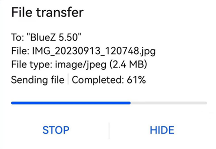
The received file is saved in the /tmp directory.
Send files from the development board
Similarly, the OK3562-UP4 can send files to a mobile device. The testing procedure is as follows:
To send a file from the OK3562-UP4 development board to a mobile device, follow the testing procedure below:
root@OK-x-UP4:~# fltest_obexctl.sh		                             //Open obexctl
[NEW] Client /org/bluez/obex
[obex]# connect 2C:DB:07:C7:4F:F6	                     					 //Connect to the Bluetooth MAC that needs to communicate
Attempting to connect to 2C:DB:07:C7:4F:F6
[NEW] Session /org/bluez/obex/client/session1 [default]
[NEW] ObjectPush /org/bluez/obex/client/session1
Connection successful
[C4:E1:A1:BA:A4:9E]# send /userdata/media/test.mp3	      		   //Send files
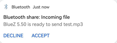
Your mobile phone will receive a request to receive a file; tap “Accept” to transfer the file.
4.1.19 4G
Note:
When using an IoT card for testing, confirm the module firmware version; lower versions may not support it and require an upgrade of the EC20 firmware;
Some IoT cards require a dedicated account and password for dial-up; please adjust the command based on your actual situation;
You can use the quectelCM –help command to view the meanings of related parameters.
The OK3562-UP4 supports a 4G module EC20. Connect the 4G module and insert the SIM card before powering on the development board.
1. After connecting the module and powering on the development board and module, you can check the USB status using the lsusb command.
root@OK-x-UP4:~# lsusb
Bus 001 Device 001: ID 1d6b:0002
Bus 001 Device 004: ID 0bda:9210
Bus 001 Device 003: ID 17ef:608d
Bus 001 Device 002: ID 1a40:0101
Bus 002 Device 001: ID 1d6b:0001
Bus 002 Device 003: ID 2c7c:0125	                             //EC20 VID and PID
Check the device node status under /dev.:
root@OK-x-UP4:~# ls /dev/ttyUSB*
/dev/ttyUSB0  /dev/ttyUSB1  /dev/ttyUSB2  /dev/ttyUSB3
After successful device identification, you can perform dial-up Internet access testing; fltest_quectel.sh calls quectelCM; for the specific commands, please refer to /usr/bin/fltest_quectel.sh
root@OK-x-UP4:~# fltest_quectel.sh &
Print information as follows:
[04-24_11:07:50:740] Find /sys/bus/usb/devices/3-1.1 idVendor=0x2c7c idProduct=0x125, bus=0x003, dev=0x004
[04-24_11:07:50:740] Auto find qmichannel = /dev/qcqmi0
[04-24_11:07:50:740] Auto find usbnet_adapter = usb0
[04-24_11:07:50:741] netcard driver = GobiNet, driver version = V1.6.2.14
[04-24_11:07:53:343] ioctl(0x89f3, qmap_settings) failed: Operation not supported, rc=-1
[04-24_11:07:53:344] Modem works in QMI mode
[04-24_11:07:53:375] Get clientWDS = 7
[04-24_11:07:53:407] Get clientDMS = 8
[04-24_11:07:53:439] Get clientNAS = 9
[04-24_11:07:53:471] Get clientUIM = 10
[04-24_11:07:53:503] Get clientWDA = 11
[04-24_11:07:53:535] requestBaseBandVersion EC20CEHDLGR06A09M1G
[04-24_11:07:53:695] requestGetSIMStatus SIMStatus: SIM_READY
[04-24_11:07:53:728] requestGetProfile[1] cmnet///0
[04-24_11:07:53:760] requestRegistrationState2 MCC: 460, MNC: 0, PS: Detached, DataCap: UNKNOW
[04-24_11:07:53:791] requestQueryDataCall IPv4ConnectionStatus: DISCONNECTED
[04-24_11:07:53:791] ifconfig usb0 0.0.0.0
[   25.728538] IPv6: ADDRCONF(NETDEV_CHANGE): usb0: link becomes ready
[04-24_11:07:53:807] ifconfig usb0 down
[04-24_11:07:53:855] requestRegistrationState2 MCC: 460, MNC: 0, PS: Detached, DataCap: UNKNOW
[04-24_11:07:54:783] requestRegistrationState2 MCC: 460, MNC: 0, PS: Attached, DataCap: LTE
[04-24_11:07:54:847] requestSetupDataCall WdsConnectionIPv4Handle: 0x86d9ed50
[04-24_11:07:54:975] requestRegistrationState2 MCC: 460, MNC: 0, PS: Attached, DataCap: LTE
[04-24_11:07:55:009] requestRegistrationState2 MCC: 460, MNC: 0, PS: Attached, DataCap: LTE
[04-24_11:07:55:072] ifconfig usb0 up
[04-24_11:07:55:087] udhcpc -f -n -q -t 5 -i usb0
udhcpc: started, v1.36.0
udhcpc: broadcasting discover
udhcpc: broadcasting select for 10.255.105.171, server 10.255.105.172
udhcpc: lease of 10.255.105.171 obtained from 10.255.105.172, lease time 7200
[04-24_11:07:55:370] deleting routers
[04-24_11:07:55:417] adding dns 111.11.1.3
[04-24_11:07:55:418] adding dns 111.11.11.3
Before testing, check the relevant settings.
View gateway configuration:
root@OK-x-UP4:/# route
Kernel IP routing table
Destination     Gateway         Genmask         Flags Metric Ref    Use Iface
default         10.255.105.172  0.0.0.0         UG    0      0        0 usb0
10.255.105.168  *               255.255.255.248 U     0      0        0 usb0
View DNS configuration:
root@OK-x-UP4:/# cat /etc/resolv.conf
nameserver 111.11.1.3 # usb0
nameserver 111.11.11.3 # usb0
Once you have configured the DNS and routing, you can ping the domain name:
root@OK-x-UP4:~# ping -i usb0 www.baidu.com -c 3									//Specify usb0 NIC to ping 3 times
PING www.a.shifen.com (110.242.68.4) from 10.52.86.52 wwan0: 56(84) bytes of data.
64 bytes from 110.242.68.4 (110.242.68.4): icmp_seq=1 ttl=55 time=47.4 ms
64 bytes from 110.242.68.4 (110.242.68.4): icmp_seq=2 ttl=55 time=54.2 ms
64 bytes from 110.242.68.4 (110.242.68.4): icmp_seq=3 ttl=55 time=40.2 ms
--- www.a.shifen.com ping statistics ---
3 packets transmitted, 3 received, 0% packet loss, time 2003ms
rtt min/avg/max/mdev = 40.239/47.300/54.259/5.724 ms
4.1.20 Audio Playback/Recording Test
There are two standard 3.5mm audio sockets: three white XH2.0-2P sockets (P39, P43 and P37), capable of driving 8Ω speakers with a maximum output power of 1W. Before conducting an audio playback test, please plug your headphones into the headphone jack or connect the speakers to the corresponding sockets on the carrier board for testing.
Playing audio using the rk809 codec:
root@OK-x-UP4:/# aplay -l
**** List of PLAYBACK Hardware Devices ****
card 0: rockchiprk809 [rockchip-rk809], device 0: dailink-multicodecs rk817-hifi-0 [dailink-multicodecs rk817-hifi-0]
  Subdevices: 1/1
  Subdevice #0: subdevice #0
card 1: rockchipnau8822 [rockchip-nau8822], device 0: dailink-multicodecs nau8822-hifi-0 [dailink-multicodecs nau8822-hifi-0]
  Subdevices: 1/1
  Subdevice #0: subdevice #0
Play sound (plug your headphones into P40, or plug your speakers into P39).
root@OK-x-UP4:/# gst-play-1.0 /userdata/media/test.mp3 --audiosink="alsasink device=plughw:0,0"
MIC input
root@OK-x-UP4:/# arecord -l
**** List of CAPTURE Hardware Devices ****
card 0: rockchiprk809 [rockchip-rk809], device 0: dailink-multicodecs rk817-hifi-0 [dailink-multicodecs rk817-hifi-0]
  Subdevices: 1/1
  Subdevice #0: subdevice #0
card 1: rockchipnau8822 [rockchip-nau8822], device 0: dailink-multicodecs nau8822-hifi-0 [dailink-multicodecs nau8822-hifi-0]
  Subdevices: 1/1
  Subdevice #0: subdevice #0
root@OK-x-UP4:/# arecord -D hw:rockchiprk809,0 -d 3 -f cd -t wav test1.wav
root@OK-x-UP4:/# aplay -D plughw:0,0 test1.wav //Play the collected sound
Playing audio using the nau8822 codec:
root@OK-x-UP4:/# aplay -l
**** List of PLAYBACK Hardware Devices ****
card 0: rockchiprk809 [rockchip-rk809], device 0: dailink-multicodecs rk817-hifi-0 [dailink-multicodecs rk817-hifi-0]
  Subdevices: 1/1
  Subdevice #0: subdevice #0
card 1: rockchipnau8822 [rockchip-nau8822], device 0: dailink-multicodecs nau8822-hifi-0 [dailink-multicodecs nau8822-hifi-0]
  Subdevices: 1/1
  Subdevice #0: subdevice #0
Play sound (plug headphones into P41, or plug speakers into P43 or P37)
root@OK-x-UP4:/# gst-play-1.0 /userdata/media/test.mp3 --audiosink="alsasink device=plughw:1,0"
MIC input
root@OK-x-UP4:/# arecord -l
**** List of CAPTURE Hardware Devices ****
card 0: rockchiprk809 [rockchip-rk809], device 0: dailink-multicodecs rk817-hifi-0 [dailink-multicodecs rk817-hifi-0]
  Subdevices: 1/1
  Subdevice #0: subdevice #0
card 1: rockchipnau8822 [rockchip-nau8822], device 0: dailink-multicodecs nau8822-hifi-0 [dailink-multicodecs nau8822-hifi-0]
  Subdevices: 1/1
  Subdevice #0: subdevice #0
root@OK-x-UP4:/# arecord -D hw:rockchipnau8822,0 -d 3 -f cd -t wav test1.wav
root@OK-x-UP4:/# aplay -D plughw:1,0 test1.wav //Play the collected sound
4.1.21 LCD Backlight Adjustment
The brightness range for the backlight is (0–255), where 255 indicates the highest brightness and 0 turns off the backlight. Connect a MIPI display to MIPI DSI0 and power on the board. Enter the following command in the terminal after system startup for backlight testing.
Check the current screen backlight value:
root@OK-x-UP4:~# cat /sys/class/backlight/backlight/brightness
200                                           			//The current backlight value is 200
Turn off the backlight:
root@OK-x-UP4:~# echo 0 > /sys/class/backlight/backlight/brightness
Turn on the LCD backlight:
root@OK-x-UP4:~# echo 125 > /sys/class/backlight/backlight/brightness
4.1.22 CAN Test
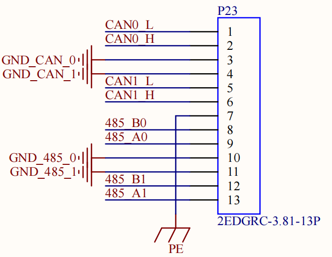
The industrial-grade configuration of the OK3562-UP4 platform features two CAN bus interfaces. CAN connection methods: The CAN_H terminal is connected to the H terminal of other CAN devices.
The CAN_L terminal is connected to the L terminal of other CAN devices.
Short-circuit CAN0 and CAN1, and short-circuit the CAN1_L, CAN0_L, CAN1_H and CAN0_H pin headers on port P23, as shown in the figure:
Execute the following command in the terminal on the development board:
View CAN network devices:
root@OK-x-UP4:/# ifconfig -a
can0      Link encap:UNSPEC  HWaddr 00-00-00-00-00-00-00-00-00-00-00-00-00-00-00-00
          NOARP  MTU:16  Metric:1
          RX packets:0 errors:0 dropped:0 overruns:0 frame:0
          TX packets:0 errors:0 dropped:0 overruns:0 carrier:0
          collisions:0 txqueuelen:10
          RX bytes:0 (0.0 B)  TX bytes:0 (0.0 B)
          Interrupt:78

can1      Link encap:UNSPEC  HWaddr 00-00-00-00-00-00-00-00-00-00-00-00-00-00-00-00
          NOARP  MTU:16  Metric:1
          RX packets:0 errors:0 dropped:0 overruns:0 frame:0
          TX packets:0 errors:0 dropped:0 overruns:0 carrier:0
          collisions:0 txqueuelen:10
          RX bytes:0 (0.0 B)  TX bytes:0 (0.0 B)
          Interrupt:79
CAN device baud rate:
root@OK-x-UP4:/# ip link set can0 type can bitrate 500000
root@OK-x-UP4:/# ip link set can1 type can bitrate 500000
Set the baud rate for the can0 and can1 devices to 500,000.
Turn on the CAN device:
root@OK-x-UP4:/# ifconfig can0 up
root@OK-x-UP4:/# ifconfig can1 up
The client sends data and the server receives data:
When the can0 device acts as the server (the server must first execute the following command):
root@OK-x-UP4:/# candump can0 &
When device can1 acts as the client (the client sends data):
root@OK-x-UP4:/# cansend can1 1F334455#1122334455667788
  can0  1F334455   [8]  11 22 33 44 55 66 77 88
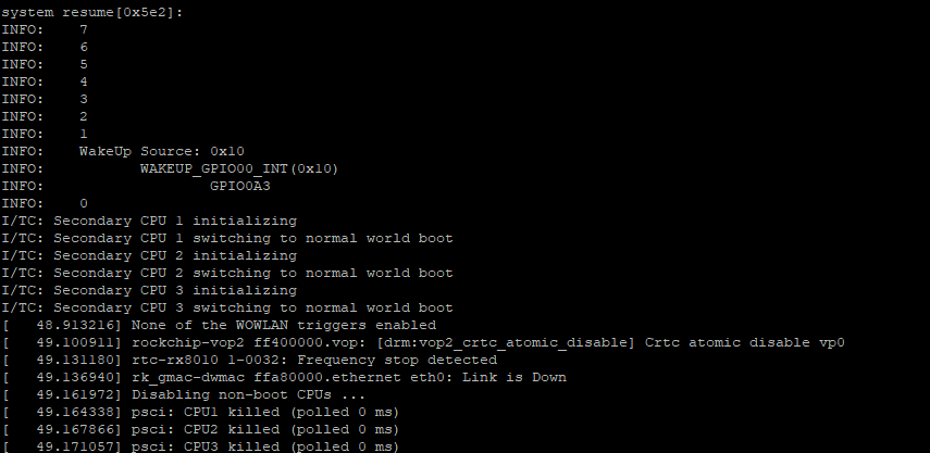
4.1.23 Sleep and Wake-Up Test
The OK3562-UP4 platform supports sleep-to-wake functionality; the sleep-to-wake button is the PWRON button on the carrier board.
Short press PWRON:
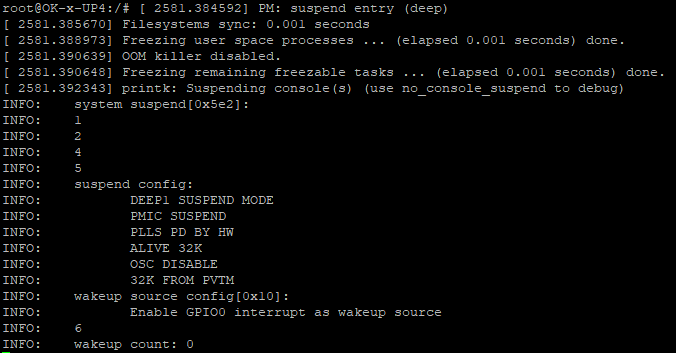
Short press the PWRon key to wake up again:
4.1.24 SQLite3 Test
SQLite3 is a lightweight database system, an ACID-compliant relational database management system with low resource consumption. The OK3562-UP4 development board uses version 3.21.0 of SQLite3.
root@OK-x-UP4:/# sqlite3
SQLite version 3.39.2 2022-07-21 15:24:47
Enter ".help" for usage hints.
Connected to a transient in-memory database.
Use ".open FILENAME" to reopen on a persistent database.
sqlite> create table tbl1 (one varchar(10), two smallint);	//Create table tbl1
sqlite> insert into tbl1 values('hello!',10);								//Insert data hello!|10 in table tbl1
sqlite> insert into tbl1 values('goodbye', 20);							//Insert data goodbye|20 in table tbl1
sqlite> select * from tbl1;																	//Query the contents of table tbl1
hello!|10
goodbye|20
sqlite> delete from tbl1 where one = 'hello!';							//Delete data
sqlite> select * from tbl1;																	//Query the contents of table tbl1
goodbye|20
sqlite> .quit			                                					//Exit the database (or use the.exit command)
root@OK-x-UP4:/#
4.1.25 SPI Test
The SPI test pin is led out from the OK3562-UP4 carrier board; it is located at P31.
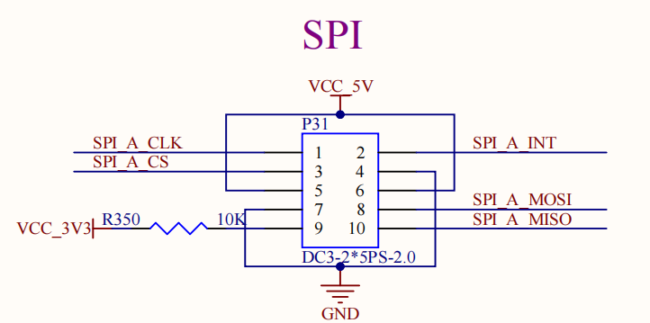
Short-circuit the SPI_A_MOSI and SPI_A_MISO pins.
root@OK-x-UP4:/# fltest_spidev_test -D /dev/spidev2.0
 spi mode: 0
bits per word: 8
max speed: 500000 Hz (500 KHz)

FF FF FF FF FF FF
40 00 00 00 00 95
FF FF FF FF FF FF
FF FF FF FF FF FF
FF FF FF FF FF FF
DE AD BE EF BA AD
F0 0D
PASS
4.1.26 Adding a Startup Script
Temporarily Adding a Startup Script
Simply edit /etc/autorun.sh:
root@OK-x-UP4:/# cat /etc/autorun.sh
#! /bin/sh
# env

# user command

exit 0
Restart the board for verification.
To add a startup script into the flashed image:
Modify buildroot/board/forlinx/ok3562-up4/fs-overlay/etc/autorun.sh.
Then recompile, repack, and flash the image.
5. OK3562J-UP4 Platform Multimedia Testing
The OK3562-UP4 platform uses Gstreamer for audio and video applications, which supports hardware-accelerated encoding and decoding. All examples in this section are based on Gstreamer commands. If you need a player with a GUI, you can also use Qt multimedia classes, which also support hardware-accelerated encoding. Please refer to the Qt test section for more details.
There is a Video Processing Unit (VPU) that supports the following video hardware encoding/decoding formats:
Video Decoding: H264, H265, VP9, supporting up to 4Kx2K@30fps.
Video Encoding H264, supporting up to 1080p@60fps.
OK3562-UP4 Hardware Encoding and Decoding Parameter Table
Video Decoder |
Format |
Profile |
Resolution |
Frame rate |
|---|---|---|---|---|
H.265 |
Main Profile yuv420@L5.0 |
4096×2304 |
30 fps |
|
H.264 |
Main Profile yuv400/yuv420/yuv422/@L5.0 |
1920x1080 |
60 fps |
|
VP9 |
Profile0 yuv420@L5.0 |
4096x2304 |
30fps |
|
Video Encoder |
H.264 |
High Profile level4.2 |
1920x1080 |
60 fps |
5.1 Audio and Video Playback Experience
5.1.1 Playing Video and Audio via Gst-play
Gplay is an audio and video player based on Gstreamer. It automatically selects the appropriate plugins for audio and video playback based on the hardware, and it is very easy to use.
root@OK-x-UP4:/# gst-play-1.0 /userdata/media/1080p_60fps_h264-30S.mp4
//Play a video file with sound and test the audio output through headphones
Press 'k' to see a list of keyboard shortcuts.
Now playing /userdata/media/1080p_60fps_h265-30S.mp4
Redistribute latency...
Redistribute latency...
Redistribute latency...
0:00:30.0 / 0:00:30.0
Reached end of play list.
5.1.2 Playing Video via Gst-launch
root@OK-x-UP4:/# gst-launch-1.0 filesrc location=/userdata/media/4k_30fps_h265-30S.mp4 ! qtdemux ! queue ! h265parse ! mppvideodec ! waylandsink
//Play video only
Setting pipeline to PAUSED ...
Pipeline is PREROLLING ...
Pipeline is PREROLLED ...
Setting pipeline to PLAYING ...
Redistribute latency...
New clock: GstSystemClock
0:00:01.0 / 0:00:30.0 (3.6 %)
5.1.3 Playing Audio via Gst-launch
root@OK-x-UP4:/# gst-launch-1.0 filesrc location=/userdata/media/test.mp3 ! id3demux ! mpegaudioparse ! mpg123audiodec ! alsasink device=plughw:0,0
//仅播放音频,由耳机放音测试,
Setting pipeline to PAUSED ...
Pipeline is PREROLLING ...
Redistribute latency...
Pipeline is PREROLLED ...
Setting pipeline to PLAYING ...
New clock: GstAudioSinkClock
handling interrupt.
Interrupt: Stopping pipeline ...
Execution ended after 0:00:02.665159268
Setting pipeline to PAUSED ...
Setting pipeline to READY ...
Setting pipeline to NULL ...
Freeing pipeline ...
5.1.4 Playing Both Video and Audio via Gst-launch
root@OK-x-UP4:/# gst-launch-1.0 filesrc location=/userdata/media/4k_30fps_h265-30S.mp4 ! qtdemux name=dec dec. ! queue ! h265parse ! mppvideodec ! waylandsink dec. ! queue ! decodebin ! alsasink device=plughw:0,0
//Play the video file with sound, and test the sound by the earphone
Setting pipeline to PAUSED ...
Pipeline is PREROLLING ...
Redistribute latency...
Redistribute latency...
Pipeline is PREROLLED ...
Setting pipeline to PLAYING ...
Redistribute latency...
New clock: GstAudioSinkClock
^Chandling interrupt. (2.6 %)
5.2 Video Hardware Encoding
The OK3562-UP4 supports H.264 at a maximum resolution of 1920x1080@60fps.
5.2.1 Video Hardware Encoding H.264
root@OK-x-UP4:/# gst-launch-1.0 videotestsrc num-buffers=600 ! video/x-raw,framerate=60/1,width=1920,height=1080 ! mpph264enc ! h264parse ! mp4mux ! filesink location=test.mp4
Setting pipeline to PAUSED ...
Pipeline is PREROLLING ...
Pipeline is PREROLLED ...
Setting pipeline to PLAYING ...
Redistribute latency...
New clock: GstSystemClock
0:00:18.2 / 0:00:20.0 (91.0 %)
5.3 Video Hardware Decoding
The OK3562-UP4 supports hardware video decoding for H.264, H.265. The H.264 decoder supports up to 1920x1080@60fps, while the H.265 decoder supports up to 4K@30fps.
The OK3562-UP4 uses the mppvideodec component for video hardware decoding, and its output formats are NV12, I420, and YV12.
5.3.1 H.264 Video Decoding and Playback
root@OK-x-UP4:/# gst-launch-1.0 filesrc location=/userdata/media/1080p_60fps_h264-30S.mp4 ! qtdemux ! h264parse ! mppvideodec ! waylandsink
Pipeline is PREROLLING ...
[ 1705.438451] dwhdmi-rockchip fde80000.hdmi: Rate 266625000 missing; computeRedistribute latency. ..
NRedistribute latency...
 dynamically
Pipeline is PREROLLED ...
Setting pipeline to PLAYING ...
Redistribute latency...
New clock: GstAudioSinkClock
0:00:01.4 / 0:00:30.0 (4.8 %)
5.3.2 H.264 Video Decoding and Playback with Audio
root@OK-x-UP4:/# gst-launch-1.0 filesrc location=/userdata/media/1080p_60fps_h264-30S.mp4 ! qtdemux name=demux demux.video_0 ! queue ! h264parse ! mppvideodec ! waylandsink demux.audio_0 ! queue ! aacparse ! faad ! alsasink device=plughw:0,0
Pipeline is PREROLLING ...
[ 1705.438451] dwhdmi-rockchip fde80000.hdmi: Rate 266625000 missing; computeRedistribute latency. ..
NRedistribute latency...
 dynamically
Pipeline is PREROLLED ...
Setting pipeline to PLAYING ...
Redistribute latency...
New clock: GstAudioSinkClock
0:00:01.4 / 0:00:30.0 (4.8 %)
5.3.3 H.265 Video Decoding and Playback
root@OK-x-UP4:/# gst-launch-1.0 filesrc location=/userdata/media/4k_30fps_h265-30S.mp4 ! qtdemux ! h265parse ! mppvideodec ! waylandsink
Pipeline is PREROLLING ...
[ 1705.438451] dwhdmi-rockchip fde80000.hdmi: Rate 266625000 missing; computeRedistribute latency. ..
NRedistribute latency...
 dynamically
Pipeline is PREROLLED ...
Setting pipeline to PLAYING ...
Redistribute latency...
New clock: GstAudioSinkClock
0:00:01.4 / 0:00:30.0 (4.8 %)
5.3.4 H.265 Video Decoding and Playback with Audio
root@OK-x-UP4:/# gst-launch-1.0 filesrc location=/userdata/media/4k_30fps_h265-30S.mp4 ! qtdemux name=demux demux.video_0 ! queue ! h265parse ! mppvideodec ! waylandsink demux.audio_0 ! queue ! aacparse ! faad ! alsasink device=plughw:0,0
Pipeline is PREROLLING ...
[ 1705.438451] dwhdmi-rockchip fde80000.hdmi: Rate 266625000 missing; computeRedistribute latency. ..
NRedistribute latency...
 dynamically
Pipeline is PREROLLED ...
Setting pipeline to PLAYING ...
Redistribute latency...
New clock: GstAudioSinkClock
0:00:01.4 / 0:00:30.0 (4.8 %)
5.3.5 V9 Video Decoding and Playback
root@OK-x-UP4:/# gst-launch-1.0 filesrc location=/userdata/media/4k_30fps_vp9-30S.mp4 ! qtdemux name=dec dec. ! queue ! vp9parse ! mppvideodec ! waylandsink
Pipeline is PREROLLING ...
[ 1705.438451] dwhdmi-rockchip fde80000.hdmi: Rate 266625000 missing; computeRedistribute latency. ..
NRedistribute latency...
 dynamically
Pipeline is PREROLLED ...
Setting pipeline to PLAYING ...
Redistribute latency...
New clock: GstAudioSinkClock
0:00:01.4 / 0:00:30.0 (4.8 %)
5.3.6 V9 Video Decoding and Playback with Audio
root@OK-x-UP4:/# gst-launch-1.0 filesrc location=/userdata/media/4k_30fps_vp9-30S.mp4 ! qtdemux name=dec dec. ! queue ! vp9parse ! mppvideodec ! waylandsink dec. ! queue ! decodebin ! alsasink device=plughw:0,0
Pipeline is PREROLLING ...
[ 1705.438451] dwhdmi-rockchip fde80000.hdmi: Rate 266625000 missing; computeRedistribute latency. ..
NRedistribute latency...
 dynamically
Pipeline is PREROLLED ...
Setting pipeline to PLAYING ...
Redistribute latency...
New clock: GstAudioSinkClock
0:00:01.4 / 0:00:30.0 (4.8 %)
5.4 Camera Test
The OK3562-UP4 supports the OV13855 MIPI camera and also supports UVC cameras. First test UVC camera, using the Logitech C270 as an example. Insert the USB camera into the development board, and the uvc driver will automatically install.
5.4.1 UVC Camera Test
5.4.1.1 Camera Recognition and Format Support Query
Camera Recognition
root@OK-x-UP4:/# v4l2-ctl --list-devices	//View the device node, and see that/dev/video40 & 41 is the USB camera node.
rk rkisp-statistics (platform: rkisp):
        /dev/video38
        /dev/video39

rkcif-mipi-lvds (platform:rkcif):
        /dev/media0
        /dev/media1
        /dev/media2
        ……..

WIN2 USB2.0 PC Camera: WIN2 USB (usb-fed00000.usb-1.3):
        /dev/video40
        /dev/video41
        /dev/media4
Query on supported formats
root@OK-x-UP4:/# v4l2-ctl --list-formats-ext -d /dev/video40 	//View the formats supported by the camera
ioctl: VIDIOC_ENUM_FMT
        Type: Video Capture

        [0]: 'YUYV' (YUYV 4:2:2)
                Size: Discrete 640x480
                        Interval: Discrete 0.033s (30.000 fps)
                Size: Discrete 352x288
                        Interval: Discrete 0.033s (30.000 fps)
                Size: Discrete 320x240
                        Interval: Discrete 0.033s (30.000 fps)
                Size: Discrete 176x144
                        Interval: Discrete 0.033s (30.000 fps)
                Size: Discrete 160x120
                        Interval: Discrete 0.033s (30.000 fps)
5.4.1.2 Camera Capture Format Query and Modification
Capture Format Query
root@OK-x-UP4:/# v4l2-ctl -V -d /dev/video40
Format Video Capture:
        Width/Height      : 640/480
        Pixel Format      : 'YUYV' (YUYV 4:2:2)
        Field             : None
        Bytes per Line    : 1280
        Size Image        : 614400
        Colorspace        : sRGB
        Transfer Function : Rec. 709
        YCbCr/HSV Encoding: ITU-R 601
        Quantization      : Default (maps to Limited Range)
        Flags             :
5.4.1.3 Camera Image Preview and Capture
Camera Image Preview
root@OK-x-UP4:/# gst-launch-1.0 v4l2src device=/dev/video40 ! videoconvert ! video/x-raw,format=NV12,width=640,height=480 ! waylandsink
Setting pipeline to PAUSED ...
Pipeline is live and does not need PREROLL ...
Pipeline is PREROLLED ...
Setting pipeline to PLAYING ...
New clock: GstSystemClock
Redistribute latency...
0:00:19.3 / 99:99:99.
Camera Capture
root@OK-x-UP4:/# gst-launch-1.0 v4l2src device=/dev/video40 num-buffers=1 ! videoconvert ! video/x-raw,format=NV12,width=640,height=480 ! mppjpegenc ! filesink location=pic.jpg
Setting pipeline to PAUSED ...
Pipeline is live and does not need PREROLL ...
Pipeline is PREROLLED ...
Setting pipeline to PLAYING ...
New clock: GstSystemClock
Redistribute latency...
Got EOS from element "pipeline0".
Execution ended after 0:00:01.224944503
Setting pipeline to NULL ...
Freeing pipeline ...
//After the execution, check the pic. JPG file generated under the root directory
5.4.2 OV13855 Test
For sensors like the OV13855 and other raw sensors, each sensor corresponds to five device nodes:
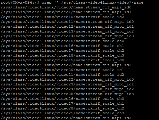
Mainpath: This is an output node from the Rockchip ISP capable of outputting full-resolution images, typically used for taking photos and capturing raw images.
Self Path: This is another output node from the Rockchip ISP that can output up to 1080p resolution, typically used for previewing.
Statistics 3A
Input-params 3A parameter settings.
The testing method for OV13855 is basically the same as for the UVC camera. This section uses the OV13855 as an example:
5.4.2.1 Camera Recognition and Format Support Query
root@OK-x-UP4:/# v4l2-ctl --list-devices			//View the device nodes
rkcif (platform:rkcif-mipi-lvds):
        /dev/video0
        /dev/video1
        /dev/video2
        /dev/video3
        /dev/video4
        /dev/video5
        /dev/video6
        /dev/video7
        /dev/video8
        /dev/video9
        /dev/video10

rkisp_mainpath (platform:rkisp-vir0):
/dev/video33
        /dev/video34
        /dev/video35
        /dev/video36
        /dev/video37
        /dev/media3

WIN2 USB2.0 PC Camera: WIN2 USB (usb-fed00000.usb-1.3):
        /dev/video40
        /dev/video41
        /dev/media4
5.4.2.2 Camera Preview
root@OK-x-UP4:/# gst-launch-1.0 v4l2src device=/dev/video33 ! video/x-raw, format=NV12, width=640, height=480, framerate=30/1 ! waylandsink
Setting pipeline to PAUSED ...
Using mplane plugin for capture

Pipeline is PREROLLED ...
Setting pipeline to PLAYING ...
New clock: GstSystemClock
Redistribute latency...
0:00:16.3 / 99:99:99.
5.4.2.3 Capture a Photo
root@OK-x-UP4:/# gst-launch-1.0 v4l2src device=/dev/video33 num-buffers=1 ! video/x-raw,format=NV12,width=640,height=480 ! mppjpegenc ! filesink location=pic.jpg
Setting pipeline to PAUSED ...
Using mplane plugin for capture
Pipeline is live and does not need PREROLL ...
Pipeline is PREROLLED ...
[19227.202218] rkisp_hw ff3f0000.isp: set isp clk = 594000000Hz
Setting pipeline to PLAYING ...
New clock: GstSystemClock
[19227.217870] rkcif-mipi-lvds2: stream[0] start streaming
[19227.217960] rockchip-mipi-csi2 mipi2-csi2: stream on, src_sd: 0000000016531031, sd_name:rockchip-csi2-dphy3
[19227.217968] rockchip-mipi-csi2 mipi2-csi2: stream ON
[19227.218003] rockchip-csi2-dphy3: dphy3, data_rate_mbps 1080
[19227.218027] rockchip-csi2-dphy csi2-dphy3: csi2_dphy_s_stream stream on:1, dphy3, ret 0
[19227.218037] ov13855 5-0036: ov13855_s_stream: on: 1, 4224x3136@30
Redistribute latency...
Got EOS from element "pipeline0".
Execution ended after 0:00:00.270035527
Setting pipeline to NULL ...
root@OK-x-UP4:/# ls -l pic.jpg
-rw-r--r-- 1 root root 15227 Apr 25 21:52 pic.jpg
5.4.2.4 H.264 Video Recording
root@OK-x-UP4:/# gst-launch-1.0 v4l2src device=/dev/video33 num-buffers=100 ! video/x-raw,format=NV12, width=640,height=480 ! tee name=t ! queue ! mpph264enc ! queue ! h264parse ! qtmux ! filesink location=13855_h264.mp4 t. ! queue ! waylandsink
//H.264 encoding during camera preview
Setting pipeline to PAUSED ...
Using mplane plugin for capture
Pipeline is live and does not need PREROLL ...
Pipeline is PREROLLED ...
Setting pipeline to PLAYING ...
New clock: GstSyst[emClock
  424.198360] rockchip-csi2-dphy csi2-dcphy0: csi2_dphy_update_sensor_mbus fail to get dphy param, used default value
[  424.200657] rkisp_hw fdcb0000.rkisp: set isp clk = 396000000Hz
[  424.204220] rkcif-mipi-lvds: stream[0] start streaming
[  424.204242] rkcifhw fdce0000.rkcif: Only support one master device, master device count 0
[  424.204260] rockchip-csi2-dphy csi2-dcphy0: csi2_dphy_update_sensor_mbus fail to get dphy param, used default value
[  424.204962] rkcif-mipi-lvds: Allocate dummy buffer, size: 0x00436000
[  424.205013] rockchip-mipi-csi2 fdd10000.mipi0-csi2: stream on, src_sd: 00000000d34b3a12, sd_name:rockchip-csi2-dphy0
[  424.205021] rockchip-mipi-csi2 fdd10000.mipi0-csi2: stream ON
i  424.205043] rockchip-csi2-dphy csRedistribute latency...
 2-dcphy0: csi2_dphy_update_sensor_mbusRedistribute latency...
 fail to get dphy param, used default value
[  424.205051] rockchip-csi2-dphy csi2-dcphy0: csi2_dphy_update_sensor_mbus fail to get dphy param, used default value
[  424.205066] rockchip-csi2-dphy0: dphy0, data_rate_mbps 600
05073] rockchip-csi2-dphy csi2-dcphy0: csi2_dphy_update_sensor_mbus fail to get dphy param, used default value
[  424.205344] rockchip-csi2-dphy csi2-dcphy0: csi2_dphy_s_stream stream on:1, dphy0
[  424.205352] rockchip-csi2-dphy csi2-dcphy0: csi2_dphy_s_stream stream on:1, dphy0
Got EOS from element "pipeline0".
Execution ended after 0:00:03.382733006
Setting pipeline to NULL ...
[  427.611291] rkcif-mipi-lvds: stream[0] start stopping, total mode 0x1, cur 0x1
Freeing pipeline ...
[  427.614953] rockchip-mipi-csi2 fdd10000.mipi0-csi2: stream off, src_sd: 00000000d34b3a12, sd_name:rockchip-csi2-dphy0
[  427.615000] rockchip-mipi-csi2 fdd10000.mipi0-csi2: stream OFF
[  427.615827] rockchip-csi2-dproot@OK-x-UP4:/# hy csi2-dcphy0: csi2_dphy_s_stream_stop stream stop, dphy0
[  427.615868] rockchip-csi2-dphy csi2-dcphy0: csi2_dphy_s_stream stream on:0, dphy0
[  427.615934] rockchip-csi2-dphy csi2-dcphy0: csi2_dphy_s_stream stream on:0, dphy0
[  427.635242] rkcif-mipi-lvds: stream[0] stopping finished
[  427.674994] rkisp rkisp0-vir1: first params buf queue
root@OK-x-UP4:/# ls -l 13855_h264.mp4          //Check whether an H.264 file has been generated
-rw-r--r-- 1 root root 417871 Apr 29 15:15 13855_h264.mp4
root@OK-x-UP4:/#
5.4.2.5 H.264 Video Playback
root@OK-x-UP4:/# gst-launch-1.0 filesrc location=13855_h264.mp4 ! qtdemux ! queue ! h264parse ! mppvideodec ! waylandsink
//Play H264 video
Setting pipeline to PAUSED ...
Pipeline is PREROLLING ...
Pipeline is PREROLLED ...
Setting pipeline to PLAYING ...
Redistribute latency...
New clock: GstSystemClock
Got EOS from element "pipeline0".
Execution ended after 0:00:03.303679248
Setting pipeline to NULL ...
Freeing pipeline ...
5.4.3 OV5645 Test
The testing method for OV5645 is basically the same as for the UVC camera. This section uses the OV5645 as an example:
5.4.2.1 Camera Recognition and Format Support Query
root@OK-x-UP4:/# v4l2-ctl --list-devices
rkisp-statistics (platform: rkisp):
        /dev/video38
        /dev/video39

rkcif-mipi-lvds (platform:rkcif):
        /dev/media0
        /dev/media1
        /dev/media2

rkcif (platform:rkcif-mipi-lvds): //Depending on the connection location, it may be rkcif-mipi-lvds1
        /dev/video0
        /dev/video1
        /dev/video2
        /dev/video3
        /dev/video4
        /dev/video5
        /dev/video6
        /dev/video7
        /dev/video8
        /dev/video9
        /dev/video10

rkisp_mainpath (platform:rkisp-vir1):
        /dev/video33
        /dev/video34
        /dev/video35
        /dev/video36
        /dev/video37
        /dev/media3
5.4.2.2 Camera Preview
rkcif-mipi-lvds corresponds to /dev/video0
rkcif-mipi-lvds1 corresponds to /dev/video11
root@OK-x-UP4:/# gst-launch-1.0 v4l2src device=/dev/video0 ! video/x-raw, format=NV12, width=640, height=480, framerate=30/1 ! waylandsink
Setting pipeline to PAUSED ...
Using mplane plugin for capture

Pipeline is PREROLLED ...
Setting pipeline to PLAYING ...
New clock: GstSystemClock
Redistribute latency...
0:00:16.3 / 99:99:99.
5.4.2.3 Capture a Photo
root@OK-x-UP4:/# gst-launch-1.0 v4l2src device=/dev/video0 num-buffers=1 ! video/x-raw,format=NV12,width=640,height=480 ! mppjpegenc ! filesink location=pic.jpg
Setting pipeline to PAUSED ...
Using mplane plugin for capture
Pipeline is live and does not need PREROLL ...
Pipeline is PREROLLED ...
Setting pipeline to PLAYING ...
New clock: GstSystemClock
Redistribute latency...
Got EOS from element "pipeline0".
Execution ended after 0:00:00.374168204
Setting pipeline to NULL ...
Freeing pipeline ...
root@OK-x-UP4:/# ls -l pic.jpg
-rw-r--r-- 1 root root 20332 Jan  1 08:04 pic.jpg
5.5 GST Fixed-Point Testing
OK3562-UP4 currently supports the video playback and positioning feature using gstreamer. Enter the following command for testing:
root@OK-x-UP4:/# gst-launch-1.0 uridecodebin uri=file:///oem/SampleVideo_1280x720_5mb.mp4 ! fpsdisplaysink name=fps0 video-sink="waylandsink render-rectangle=\"<120,180,480,300>\"" text-overlay=false & gst-launch-1.0 uridecodebin uri=file:///userdata/media/1080p_60fps_h264-30S.mp4 ! fpsdisplaysink name=fps1 video-sink="waylandsink render-rectangle=\"<600,180,480,300>\"" text-overlay=false
Screen display result:
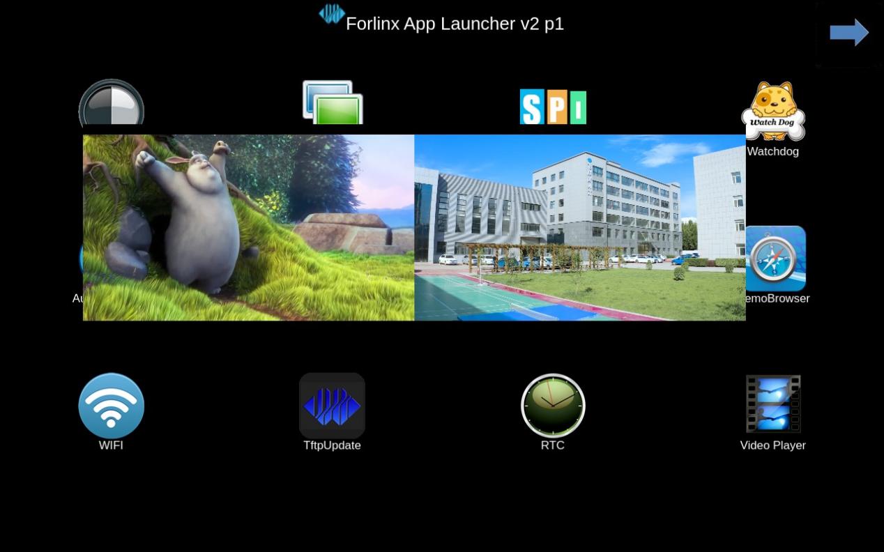
Note: During multi-channel decoding and playback of H264 1080P60 and H265 4KP30 videos, playback stuttering occurs, caused by insufficient decoding capability.
5.6 GPU Test
OK3562-UP4 supports GPU testing:
root@OK-x-UP4:/# glmark2-es2-wayland --fullscreen --visual-config='a=0:buf=24' --annotate    //Full screen test
arm_release_ver: g13p0-01eac0, rk_so_ver: 10
=======================================================
    glmark2 2023.01
=======================================================
    OpenGL Information
    GL_VENDOR:      ARM
    GL_RENDERER:    Mali-G52
    GL_VERSION:     OpenGL ES 3.2 v1.g13p0-01eac0.98c5dad4e3309b873e3189000b74ea36
    Surface Config: buf=24 r=8 g=8 b=8 a=0 depth=24 stencil=0 samples=0
    Surface Size:   1024x600 fullscreen
=======================================================
[build] use-vbo=false: FPS: 723 FrameTime: 1.385 ms
[build] use-vbo=true: FPS: 766 FrameTime: 1.306 ms
[texture] texture-filter=nearest: FPS: 1005 FrameTime: 0.996 ms
[texture] texture-filter=linear: FPS: 999 FrameTime: 1.001 ms
[texture] texture-filter=mipmap: FPS: 1014 FrameTime: 0.987 ms
[shading] shading=gouraud: FPS: 560 FrameTime: 1.788 ms
[shading] shading=blinn-phong-inf: FPS: 710 FrameTime: 1.409 ms
[shading] shading=phong: FPS: 563 FrameTime: 1.777 ms
[shading] shading=cel: FPS: 543 FrameTime: 1.842 ms
[bump] bump-render=high-poly: FPS: 309 FrameTime: 3.240 ms
[bump] bump-render=normals: FPS: 995 FrameTime: 1.005 ms
[bump] bump-render=height: FPS: 921 FrameTime: 1.087 ms
[effect2d] kernel=0,1,0;1,-4,1;0,1,0;: FPS: 390 FrameTime: 2.567 ms
[effect2d] kernel=1,1,1,1,1;1,1,1,1,1;1,1,1,1,1;: FPS: 151 FrameTime: 6.663 ms
[pulsar] light=false:quads=5:texture=false: FPS: 968 FrameTime: 1.034 ms
[desktop] blur-radius=5:effect=blur:passes=1:separable=true:windows=4: FPS: 214 FrameTime: 4.690 ms
[desktop] effect=shadow:windows=4: FPS: 674 FrameTime: 1.486 ms
[buffer] columns=200:interleave=false:update-dispersion=0.9:update-fraction=0.5:update-method=map: FPS: 140 FrameTime: 7.171 ms
[buffer] columns=200:interleave=false:update-dispersion=0.9:update-fraction=0.5:update-method=subdata: FPS: 139 FrameTime: 7.239 ms
[buffer] columns=200:interleave=true:update-dispersion=0.9:update-fraction=0.5:update-method=map: FPS: 223 FrameTime: 4.486 ms
[ideas] speed=duration: FPS: 350 FrameTime: 2.857 ms
[jellyfish] <default>: FPS: 410 FrameTime: 2.442 ms
[terrain] <default>: FPS: 32 FrameTime: 32.203 ms
[shadow] <default>: FPS: 304 FrameTime: 3.298 ms
[refract] <default>: FPS: 82 FrameTime: 12.213 ms
[conditionals] fragment-steps=0:vertex-steps=0: FPS: 965 FrameTime: 1.037 ms
[conditionals] fragment-steps=5:vertex-steps=0: FPS: 693 FrameTime: 1.445 ms
[conditionals] fragment-steps=0:vertex-steps=5: FPS: 931 FrameTime: 1.075 ms
[function] fragment-complexity=low:fragment-steps=5: FPS: 783 FrameTime: 1.279 ms
[function] fragment-complexity=medium:fragment-steps=5: FPS: 598 FrameTime: 1.673 ms
[loop] fragment-loop=false:fragment-steps=5:vertex-steps=5: FPS: 783 FrameTime: 1.279 ms
[loop] fragment-steps=5:fragment-uniform=false:vertex-steps=5: FPS: 785 FrameTime: 1.274 ms
[loop] fragment-steps=5:fragment-uniform=true:vertex-steps=5: FPS: 687 FrameTime: 1.457 ms
=======================================================
                                  glmark2 Score: 587
=======================================================
root@OK-x-UP4:/#  glmark2-es2-wayland --visual-config='a=0:buf=24' --annotate    //正常显示测试
arm_release_ver: g13p0-01eac0, rk_so_ver: 10
=======================================================
    glmark2 2023.01
=======================================================
    OpenGL Information
    GL_VENDOR:      ARM
    GL_RENDERER:    Mali-G52
    GL_VERSION:     OpenGL ES 3.2 v1.g13p0-01eac0.98c5dad4e3309b873e3189000b74ea36
    Surface Config: buf=24 r=8 g=8 b=8 a=0 depth=24 stencil=0 samples=0
    Surface Size:   1280x800 fullscreen
=======================================================
[build] use-vbo=false: FPS: 561 FrameTime: 1.783 ms
[build] use-vbo=true:
6. Flashing the System
The OK3562-UP4 development board currently supports flashing via OTG and TF Card. The corresponding programming tool is provided in the user profile, and you can choose any one of the methods for image programming.
6.1 OTG System Flashing
6.1.1 OTG Driver Installation
Path: Software Materials \ 3-Tools \DriverAssitant_v5.1.1.zip
Extract the file above to any directory and run it with administrator privileges.
Open the DriverInstall.exe program.
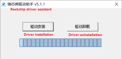
Click Install Driver.
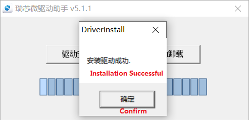
6.1.2 Complete OTG Flashing
6.1.2.1 RKDevTool Flashing Test
Path: Software Resources\3-Tools\RKDevTool_v3.19_for_window.zip
It is a development tool provided by Rockchip. Extract it to a directory with only English characters, then connect the development board TYPE-C0 to the host using a Type-C cable. Press and hold the VOL+ button on the development board, then press the reset button to reset the system. After about two seconds, release the VOL+ button. There will be prompts on the Rockchip development tool : loader device found
Note:
Device detection occurs when the VOL+ button is pressed during the power-on of the development board;
The extraction directory for Rockchip’s development tools can be arbitrary, but users have reported that the directory should contain only English characters. If the development tool interface does not match the image shown below, consider extracting it to a directory with only English characters.
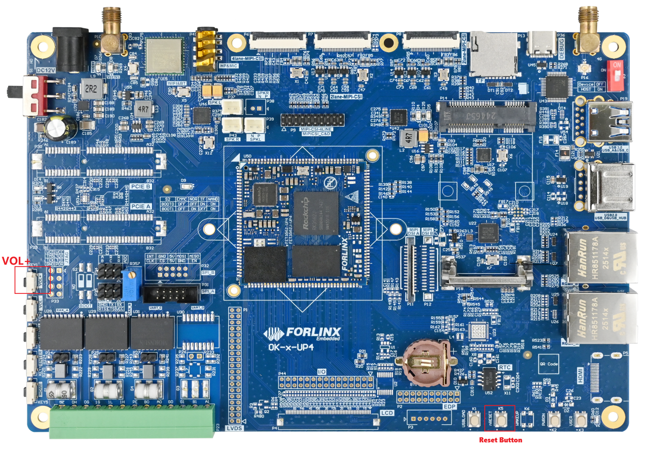
Open the Rockchip development tool:
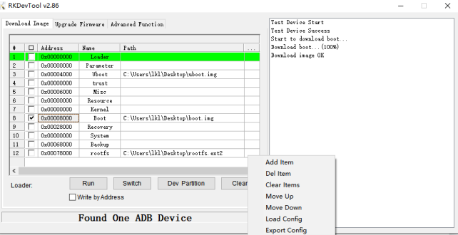
Click the “Upgrade Firmware” tab, click the “Firmware” button to select the full upgrade image update.img. The programme will analyse the firmware, so please wait a moment.
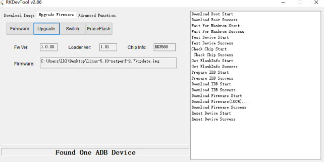
Tap “Switch” and wait for the board to enter LOADER mode, then tap the “Upgrade” button to proceed with the upgrade.
MASKROM Mode Introduction
If Loader mode is inaccessible (loader problem, etc.), press and hold the USBLOAD key, then press the reset key to enter maskrom mode for burning.
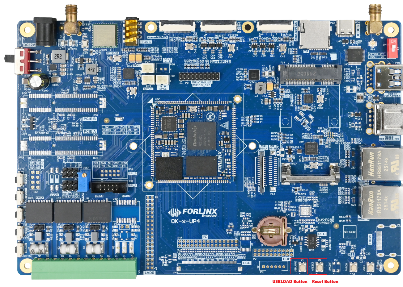
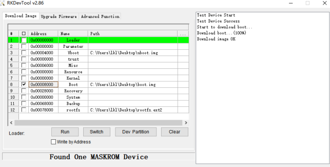
At this time, the system will prompt that a maskrom device is found. The programming process is consistent with the loader mode. It is better to use the update. img for programming.
Note:
Don’t click “Device Partition Table” in maskrom mode, it is invalid;
Flashing individually in Maskrom Mode will not clear the U-Boot environment variables.
6.1.2.2 FactoryTool Flashing Test
FactoryTool is used for batch OTG flashing in the factory. It does not require reading an image file and can batch-flash large images. If RKDevTool does not meet compatibility requirements, this method can also be attempted. Before using, extract it to a directory with only English characters. Connect the development board and host using a Type-C cable. Press and hold the VOL+ button, press the reset button for the system reset, and after about two seconds, release the VOL+ button. There will be prompts on the Rockchip development tool : loader device found
Note:
Device detection occurs when the VOL+ button is pressed during the power-on of the development board;
The extraction directory for Rockchip’s development tools can be arbitrary, but users have reported that the directory should contain only English characters. If the development tool interface does not match the image shown below, consider extracting it to a directory with only English characters.
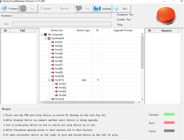
After selecting the firmware, click Start. The loader device will be detected, and the flashing process will begin automatically.
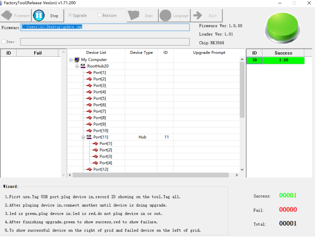
6.1.3 OTG Step-by-Step Flashing Test
During the development phase, performing full flashing every time can be time-consuming. Therefore, here it introduces how to use OTG flashing tools to flash individual partitions.
Note: Device detection occurs when the VOL+ button is pressed during the power-on of the development board.
After compiling the OK3562-UP4-source, individual partition images can be found in the rockdev directory.
Take separate flashing boot. img (including device tree and startup logo) as an example to show the flashing method.
Connect the development board to the host using a Type-C cable, hold down the VOL+ key without releasing it, then press the reset key to perform a system reset. Release the VOL+ key after approximately two seconds. The system will prompt “ Find Loader Device”.
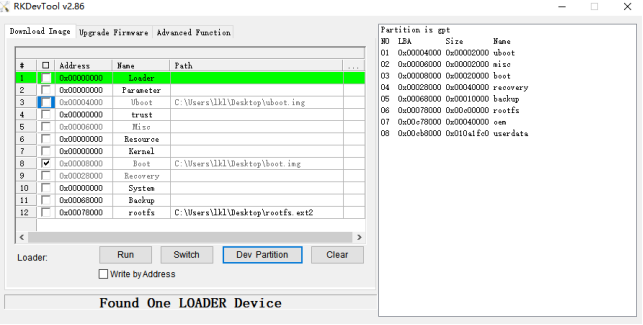
Click the Device Partition Table button. The partition addresses will be read automatically. When prompted whether to update the download address, click Yes. After the partition table is read successfully, select the partition image in the area on the right side of the partition entry and check the corresponding partition.
Click the “Execute” button to automatically flash and restart.
6.2 TF System Flashing
Flashing TF card making and testing.
Note: The maximum capacity of TF cards tested is 32GB; using a TF card with a capacity greater than 32GB may result in a write failure.
Copy SDDiskTool_v1.76.zip from the user profile tool directory to any windows directory. Run SD_Firmware_Tool.exe with administrator privileges.
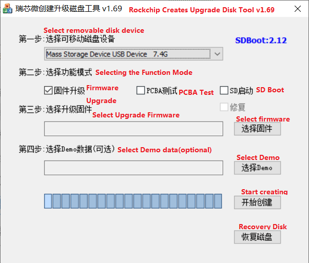
Select the disk device, tick the “Firmware Update” box, and select update.img. Click to start creating.
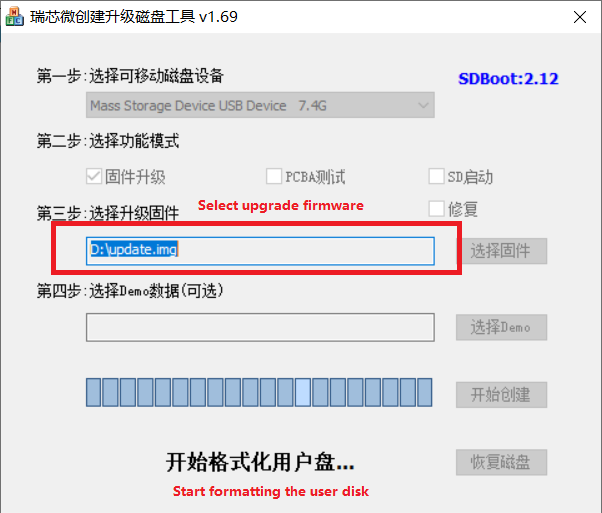
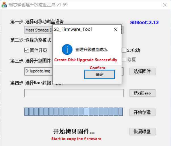
Insert the TF card into the development board and power it on; the system will automatically begin the flashing process. Once the flashing is complete, both the screen and the serial port will display the following message:
Please remove SD CARD!!!, wait for reboot.
At this point, remove the TF card and the system will restart automatically (please do not switch off the power directly).
At this time, remove the TF card, and the system will automatically restart (do not cut the power directly).
Kernel boot phase: Heartbeat light mode, flashing at regular intervals;
Preparation for programming: The eMMC indicator light is off;
Programming in progress: The eMMC indicator light remains lit;
Post-programming: Heartbeat light mode, with regular, intermittent flashing.
Serial port information during the flashing process:
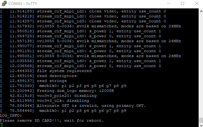
If the device does not restart automatically after removing the TF card, you can complete the flashing process by restarting it manually. Please wait patiently whilst the data is being written.