Linux5.10.198_User’s Manual_V1.0
Document classification: □ Top secret □ Secret □ Internal information ■ Open
Copyright
The copyright of this manual belongs to Baoding Folinx Embedded Technology Co., Ltd. Without the written permission of our company, no organizations or individuals have the right to copy, distribute, or reproduce any part of this manual in any form, and violators will be held legally responsible.
Forlinx adheres to copyrights of all graphics and texts used in all publications in original or license-free forms.
The drivers and utilities used for the components are subject to the copyrights of the respective manufacturers. The license conditions of the respective manufacturer are to be adhered to. Related license expenses for the operating system and applications should be calculated/declared separately by the related party or its representatives.
Overview
This manual is designed to help you quickly familiarize yourselves with the product, understand interface functions, and learn testing methods. It primarily covers the testing of development board interface functions, methods for flashing the image, and troubleshooting common issues encountered during use. During testing, certain commands have been annotated for better understanding, focusing on practicality and adequacy. For information on compiling the kernel, compiling related applications and setting up the development environment, please refer to the “Linux 5.10.198 User Compilation Manual” provided by Forlinx.
There are six chapters:
Chapter 1. briefly introduces the development board’s interface resources, relevant driver paths in the kernel source code, supported flashing and boot methods, and key points in the documentation;
Chapter 2. describes two login methods: serial port login and network login;
Chapter 3. covers functional testing of the QT interface;
Chapter 4. explains how to perform functional tests using command line operations;
Chapter 5. includes camera playback tests and video hardware encoding/decoding tests;
Chapter 6. details methods for updating the image to storage devices, allowing you to choose the appropriate flashing method based on your actual needs.
Additionally, the manual includes explanations of some symbols and formats.
Format |
Meaning |
|---|---|
// |
Explanation of input commands or output information: |
Username@Hostname |
root@OK536: Development board login account information; |
Example: After inserting the TF card, use the ls command to view the mount directory.
root@OK536:/# ls /run/media                                //List files in the/run/media directory
mmcblk0p1  mmcblk0p6  mmcblk1p1
root@OK536: The username is root, and the hostname is OK536, indicating that the operation is performed using the root user on the development board.
// : Explanation for the operation ls /run/media, no need to input.
Application Scope
This software manual is applicable to the OK536-UP4 platform with Linux5.10.198 operating system from Forlinx.
Revision History
Date |
Version |
SoM Version |
Carrier Board Version |
Revision History |
|---|---|---|---|---|
13/05/2026 |
V1.0 |
V1.0 |
V1.3 and above |
User’s Manual Initial Version |
27/07/2026 |
V1.1 |
V1.0 |
V1.3 and above |
Update to Chapter 4.27: Commands for sending files via Bluetooth. |
1. OK536-UP4 Development Board Description
1.1 OK536-UP4 Development Board Description
The OK536-UP4 development board features an SoM + carrier board design built around the Allwinner T536 processor. Operating at 1.6GHz, it integrates a quad-core Cortex-A55 CPU and a 64-bit XuanTie E907 RISC-V MCU for efficient computing. Key features include a 2TOPS NPU, support for secure boot, national cryptographic algorithms, ECC, AMP, Linux RT, and a wide range of interfaces such as USB, Ethernet, CAN, SPI, and UART.

Note: Hardware specifications are not covered in this software manual. Before development, please refer to the “ User’s Hardware Manual” to understand the product naming and hardware configuration.
1.2 Linux 5.10.198 System Software Resources
Device |
Driver Source Code Location in the Kernel |
Device Name |
|---|---|---|
Network Card Driver |
bsp/drivers/stmmac |
/sys/class/net/eth0 /sys/class/net/eth1 |
LCD Backlight Driver |
kernel/linux-5.10-origin/drivers/video/backlight/ |
|
LED Driver |
kernel/linux-5.10-origin/drivers/leds/ |
/sys/class/leds/ |
USB 4G |
kernel/linux-5.10-origin/drivers/net/usb/GobiNet/ |
/dev/ttyUSB* |
SD Card Driver |
bsp/drivers/mmc/ |
/dev/block/mmcblk_p_ |
Serial Port Driver |
bsp/drivers/uart/ |
/dev/ttyAS* |
Watchdog Driver |
bsp/drivers/watchdog/ |
/dev/watchdog |
WIFI |
drivers/net/wireless/nxp/mlan/ |
/sys/class/net/wlan0 |
Audio Driver |
bsp/drivers/sound/platform |
/dev/snd/ |
SPI |
bsp/drivers/spi/ drivers/spi/ |
/dev/spidev*.* |
TWI Driver |
bsp/drivers/twi/ |
/dev/i2c-* |
PWM Driver |
bsp/drivers/pwm/ |
/dev/sunxi_pwm* |
GT911/GT928 touch driver |
bsp/drivers/input/ctp/gt9xx/ |
/dev/input/event* |
ft5x06 touch driver |
kernel/linux-5.10-origin/drivers/input/touchscreen/edt-ft5x06.c |
/dev/input/event* |
GPADC driver |
bsp/drivers/gpadc/ |
/dev/input/event* |
LRADC button driver |
bsp/drivers/lradc/ |
/dev/input/event* |
RTC Driver |
kernel/linux-5.10-origin/drivers/rtc/rtc-rx8010.c |
/dev/rtc0 |
IR Driver |
bsp/drivers/ir-rx/ |
/dev/input/event* |
1.3 Flashing & Boot Setup
The OK536-UP4 board supports system flashing via TF card or USB OTG and boots from eMMC by default.
Insert a TF card before powering on to initiate flashing; otherwise, the system boots from eMMC. Detailed flashing steps are in the “Flashing the System” chapter.
2. Fast Startup
2.1 Preparation Before Startup
Development Login methods: Serial login and network login.
Hardware preparations before powering on the system:
12V/3A DC power cable
Debug Serial Cable (for serial port login)
The debug serial port on the development board is a Debug Type-C port. You can connect the development board to a PC using a Type-A to Type-C cable to check the board’s status information.
Ethernet cable (for network login)
Display screen — connect the screen according to the development board interface (optional if display is not needed)
Check the boot mode (if a TF card is inserted, the system will boot from the TF card by default; otherwise, it will boot from eMMC).

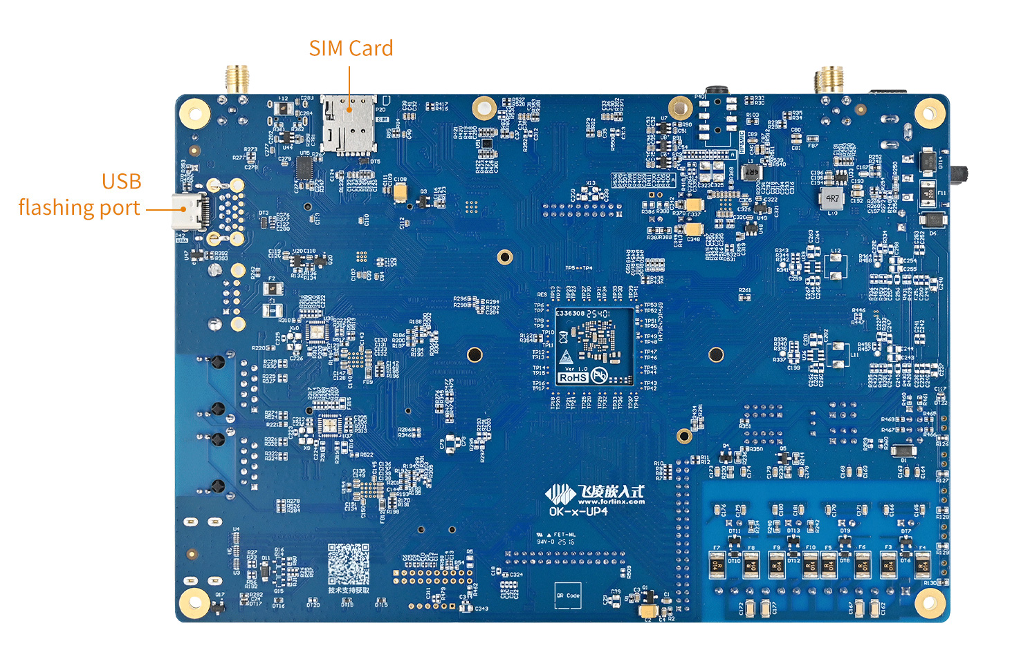
Note: The USB programming port is for programming purposes only; the USB Type-C programming port and the USB 3.0 port cannot be used simultaneously.
2.2 Serial Port Login
2.2.1 Serial Port Login
Note:
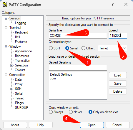
Settings: Baud rate 115200, 8 data bits, 1 stop bit, no parity/flow control;
Login: Username root, no password;
Software requirements: For Windows systems, the PC needs to have HyperTerminal software installed. There are various HyperTerminal alternatives available; one can use their preferred serial terminal software, such as PUTTY or MobaXterm.
Terminal Setup Using PuTTY (User profile\3-tools\putty-64-bit_x86.exe) as an Example:
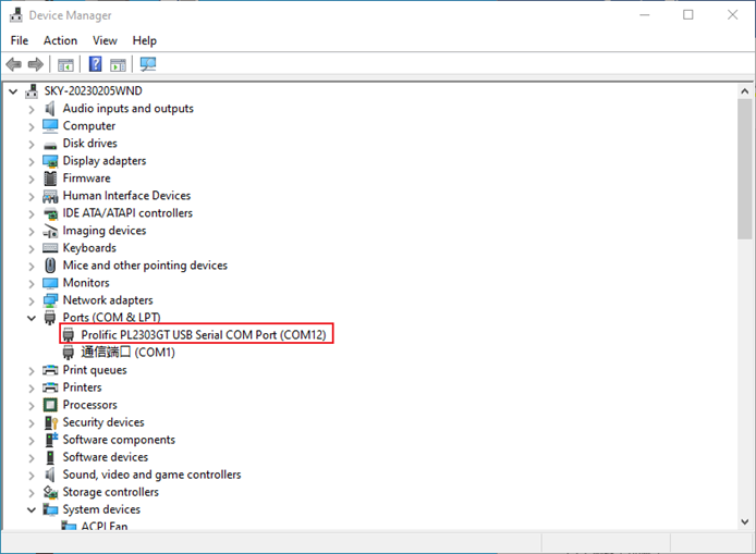
Connect the development board and PC using a serial cable. Confirm the serial port number connected to the computer by checking in “Device Manager”.
The actual serial port number recognized by the computer shall prevail. Select the accurate one.
Configure PuTTY: Open PuTTY. In the “Serial line” field, enter the identified COM port and set the baud rate to 115200;
Power on and log in: Turn on the development board.
The serial terminal will display boot-up messages. Once the prompt root@OK536:/# appears, the system has fully booted. You are logged in automatically as the root user (no password required).
2.2.2 Common Issues (Serial Login)
Driver Installation: On first connection, you may need to install the corresponding driver on your PC (located in the user materials at \03-tools\XRUSB.zip).
Cable Quality: To avoid garbled characters during communication, it is recommended to use a high-quality Type-C cable.
2.3 Network Login
2.3.1 Network Login Test
Note:
The default IP address for the eth0 interface is 192.168.0.232;
The default factory IP address for eth1 is 192.168.1.232;
The computer and the development board need to be in the same network segment during the test.
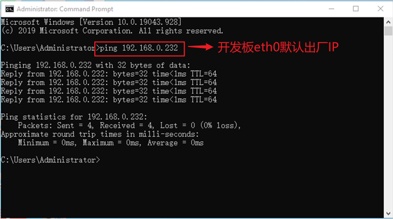
Before logging in to the network, you need to ensure that the network connection between the computer and the development board is normal. You can test the connection status between the computer and the development board through the ping command. Specific Operations:
Connect the eth0 of the development board to the computer via a network cable, power on the development board, and after the kernel starts, the Blue heartbeat light on the SoM will flash.
After the network card connected to the computer starts normally, the network card light will flash rapidly. At this point, you can test the network connection;
Disable the computer firewall.
Temporarily disable the computer’s firewall (this is a general operation; specific steps depend on your Windows version);
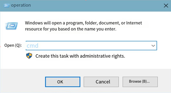
Open Command Prompt as administrator.
Press Win + R, type cmd, then press Ctrl + Shift + Enter to run Command Prompt as administrator;
Data is returned, indicating that the network connection is normal.
2.3.2 SSH Server
Note:
The default account for SSH login is “root” with the password “root”;
The default IP address for the eth0 interface is 192.168.0.232;
You can use the scp command for file transfers.
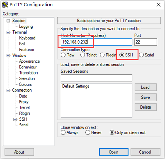
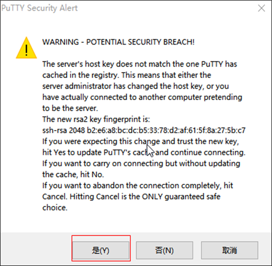
After clicking “Open”, a dialog box will appear. Click “Yes” to proceed to the login interface.
Login as:root
[email protected]'s password:               //Enter the password **root** for the development board's root account as prompted.
root@OK536:~$
You can use SFTP to copy files. For details, please refer to Section 4.17.2 SFTP.
2.5 System Storage
The OK536 is available in two configurations: 1GB RAM + 8GB Storage and 2GB RAM + 16GB Storage. The information below pertains to the 1+8GB version.
2.5.1 eMMC
The table below details the eMMC storage partition information for the Linux operating system:
Partition Index |
Name |
Size |
Filesystem |
Content |
|---|---|---|---|---|
mmcblk0p1 |
boot-resource |
32MB |
vfat |
boot-resource.fex |
mmcblk0p2 |
env |
16MB |
raw |
env.fex |
mmcblk0p3 |
boot |
96MB |
raw |
boot.fex |
mmcblk0p4 |
private |
16MB |
raw |
|
mmcblk0p5 |
rootfs |
1024MB |
ext4 |
rootfs.fex |
mmcblk0p7 |
UDISK |
Remaining Space |
ext4 |
User Partition |
Use the df command to view disk usage on the system. The following is the factory default disk usage (using the Qt filesystem) for reference only. Actual parameters may vary.
root@OK536:/ # df -Th
Filesystem         Type      Size  Used Avail Use% Mounted on
/dev/root          ext4      991M  449M  526M  47% /
tmpfs              tmpfs     459M  112K  459M   1% /tmp
tmpfs              tmpfs     459M  332K  459M   1% /run
devtmpfs           devtmpfs  457M     0  457M   0% /dev
/dev/mmcblk0p1     vfat      128M  5.3M  123M   5% /run/media/mmcblk0p1
/dev/by-name/UDISK vfat      6.1G  4.0K  6.1G   1% /mnt/UDISK
2.5.2 Memory
Use the free command to view memory usage. The following shows the memory usage when no peripherals are connected (unit: MB), for reference only. Actual parameters may vary.
root@OK536:/# free -m
              total        used        free      shared  buff/cache   available
Mem:            918         171         635           0         111         721
Swap:             0           0           0
2.6 System Shutdown
In general, you can directly power off the system. However, if operations such as data storage or functional usage are in progress, avoid cutting power abruptly to prevent irreversible file damage, which may require re-flashing the firmware. To ensure all data is fully written, you can execute the sync command to complete data synchronization before powering off.
Rebooting the Development Board: Execute the reboot command. You can also perform a hardware reset by pressing the K3 (RESET) button or directly cycling the power.
Press and hold the K1 (PWRON) button on the development board to switch it off; then press the K1 button briefly to switch it on.
Note: For products designed based on the SoM:, if unexpected power loss during use leads to system abnormalities, consider implementing measures such as power-loss protection in the design.
3. OK536-UP4 Platform Interface Function Usage and Testing
Note:
This section should be performed when you are using the screen and Qt file system. If Qt is not used, this section can be skipped;
This chapter focuses on describing the functions in Qt. During testing, it is assumed that the device connection is normal and drivers are properly loaded. It is recommended to complete command-line function testing before testing interface functions.
Qt test program source code path: source code OK536-linux-sdk/buildroot/package/auto/forlinx/qt_demo/flapp/src
Test program path in the development board file system: /usr/bin
This section mainly explains the usage of the development board’s extended interfaces in the Qt interface. The test programs are for reference only, and you need to adjust according to actual conditions during use.
3.1 Interface Function Description
After the OK536 development board starts up, the desktop is displayed as follows:
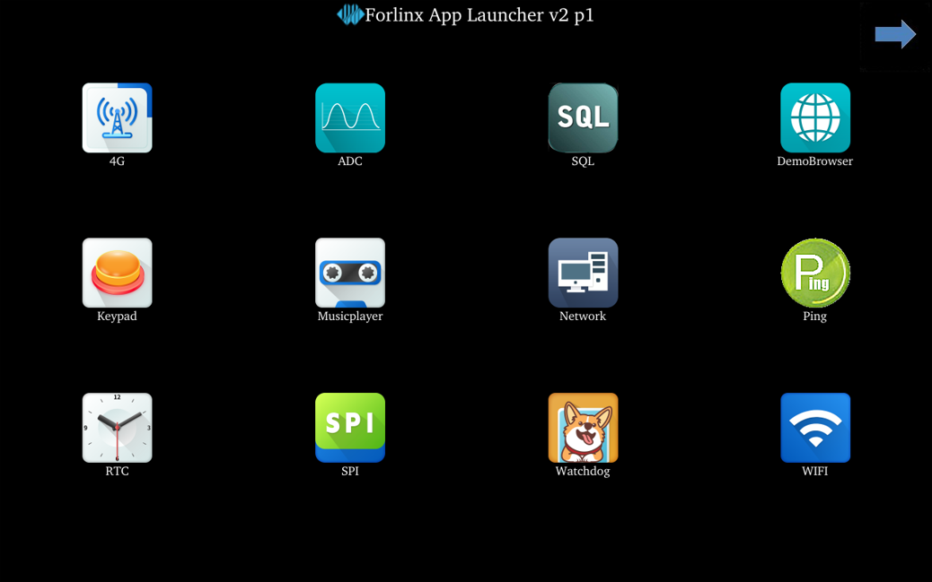
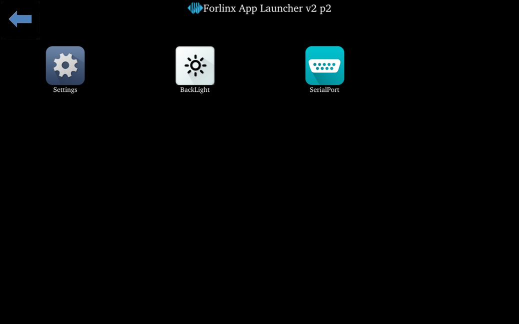
Click the arrow in the upper right corner to go to the next page.
3.2 Network Configuration Test
Note:
The factory default only sets the eth0 network card to STATIC mode;
The set IP and other information will be saved to the system’s relevant configuration file (/etc/network/interfaces), so each reboot will use the network information set this time.
Icon:
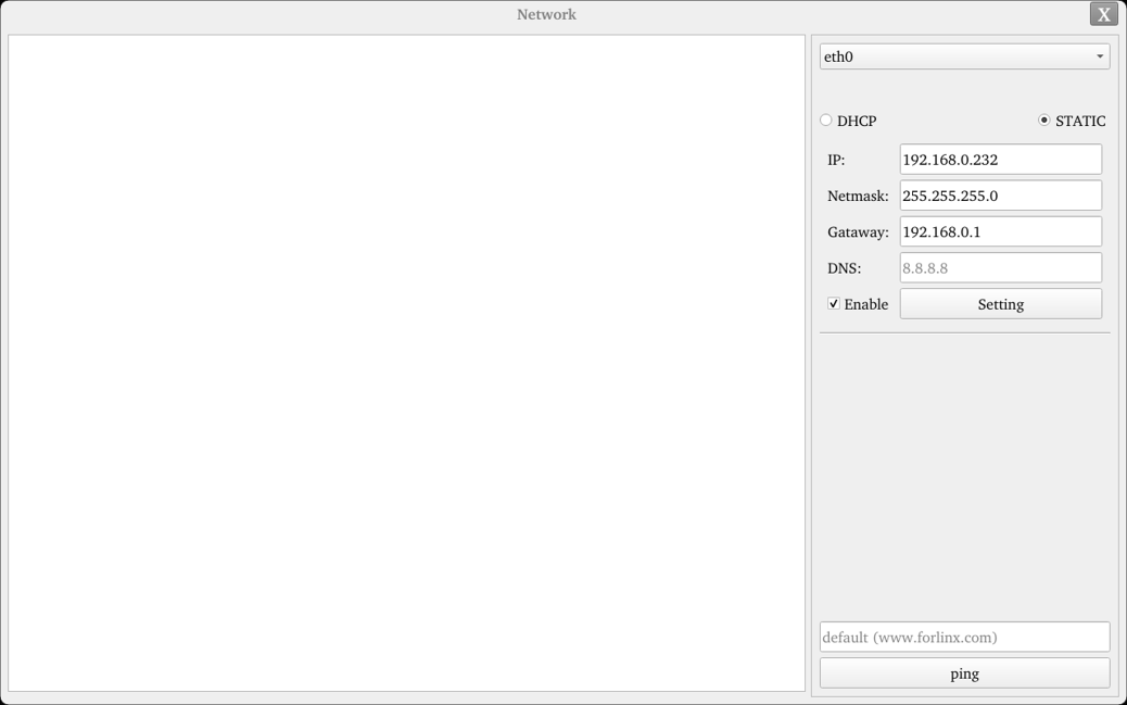
Click the network configuration icon to enter the interface program, supporting both STATIC and DHCP modes.
STATIC Mode:
Click the network configuration icon, select STATIC, as shown below: You can configure the IP address, subnet mask, gateway, and DNS. After setting the parameters, click “Apply and Restart Network”.
Relevant Parameter |
Meaning |
|---|---|
Interface |
Set network card |
IP |
Set IP address |
Netmask |
Set subnet mask |
Gateway |
Set gateway |
DNS |
Set DNS |
3.3 Browser Test
Icon:
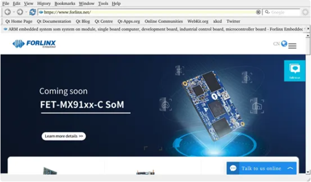
Click the browser icon to enter the browser. Ensure the network is smooth during use, and ensure DNS is available before accessing external networks. The browser defaults to accessing the Forlinx Embedded official website upon startup, as shown below:
Note: If the development board’s time is abnormal, it may cause certificate issues.
3.4 4G Test
Icon:
The “4G” test program is used to test the OK536-UP4 external 4G module (EC20). Before testing, power off the development board, switch DIP switch A to ON, connect the 4G module, insert the SIM card (pay attention to the SIM card direction), start the development board, and open the test application. This test uses EC20 as an example:
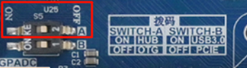

Click the start button, and the program will automatically enter the dial-up process and obtain IP, set DNS, etc. Wait patiently for a few seconds.
3.5 485 & UART Test
Icon:
This test uses UART6 (ttyAS6) and performs a serial port test with the serialTool.
Note: UART4 is a TTL serial port, whilst UART6 and UART11 are RS-485 ports. Connect the computer’s TTY-to-RS-485 converter to pins A and B of the OKT536 458; UART6 is designated as 485_0 and UART11 as 485_1.
Click the Terminal test icon to enter the following interface and set serial port parameters:
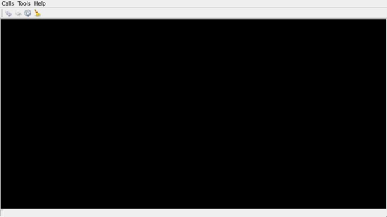
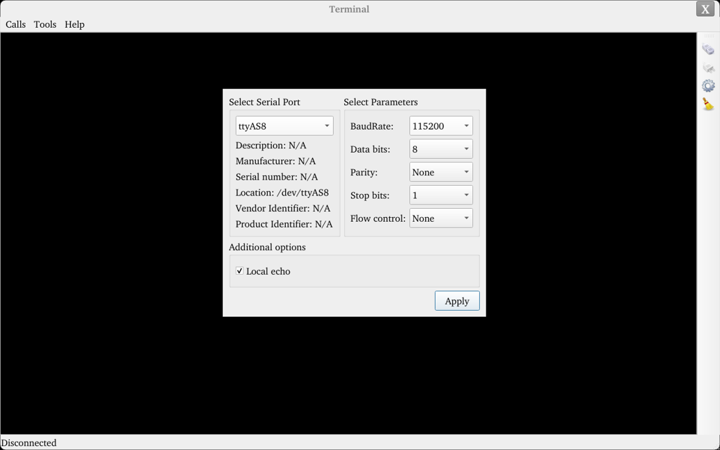
Click the settings button in the upper left corner and set the serial port parameters to be consistent with the computer-side serial port tool parameters, as shown below:
Relevant Parameter |
Meaning |
|---|---|
Select Serial Port |
Set serial port (ttyAS8) |
BaudRate |
Set baud rate (115200) |
Data bits |
Set data bits (8 bits) |
Parity |
Set parity bit (no parity) |
Stop bits |
Set stop bits (1 bit) |
Flow control |
Set flow control (no flow control) |
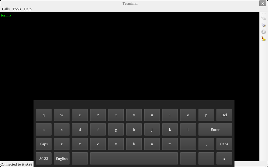
After setting the serial port parameters, click the connect button in the upper left corner. At this point, the test program can perform data transmission and receiving tests;
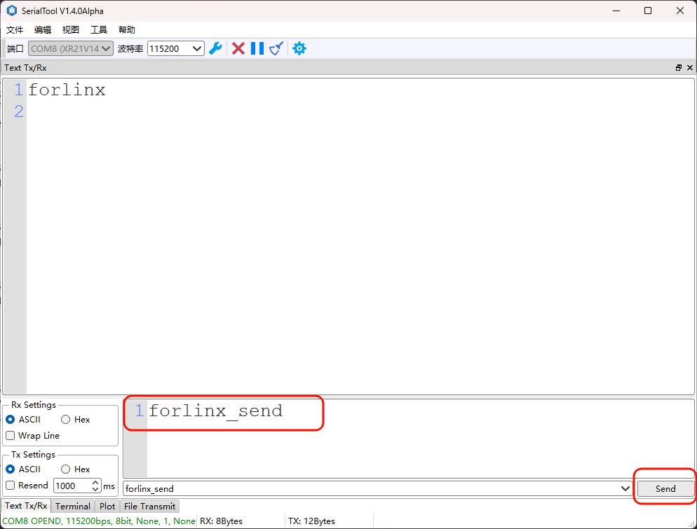
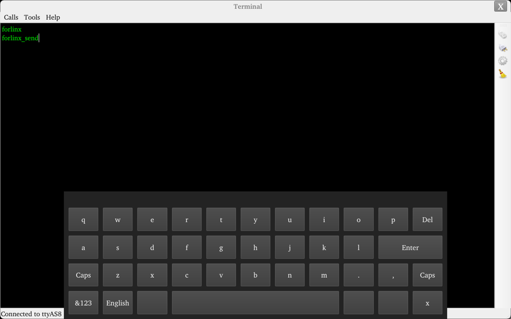
Open the serial port tool on the computer, click on the black screen area in the test interface to pop up the soft keyboard, input characters and press Enter. The screen will then display the data received by the serial port.
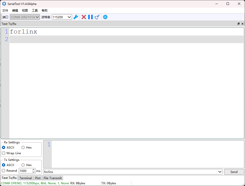
In the serialTool send box, input the content to send, click send, and the test interface will display the received content.
3.6 ADC Test
Icon:
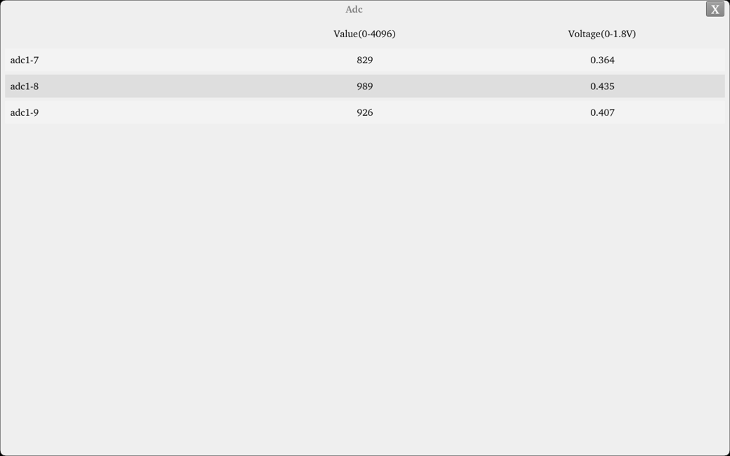
14 x GPADC are led out from the OK536 carrier board. All channels are floating by default. Short the corresponding pins to measure the potentiometer value. The maximum value 4096 corresponds to a voltage of 1.8V.
3.7 WiFi Test
Note:
The OK536 carrier board is soldered with the AW-CM358 chip;
“WIFI” is a tool for configuring WiFi and can test the STA mode of WiFi.
Click the icon to enter the test interface, select the corresponding module from the drop-down menu, enter the router name to be connected via WiFi in the SSID field, enter the router password in the PASSWORD field, and click “Connect” to connect to the router via WiFi.
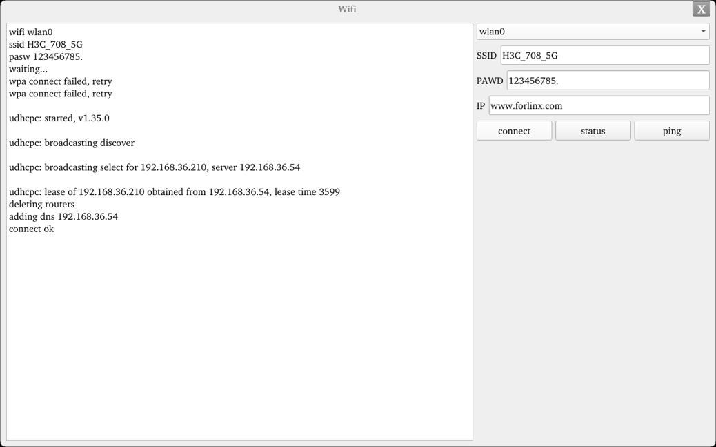
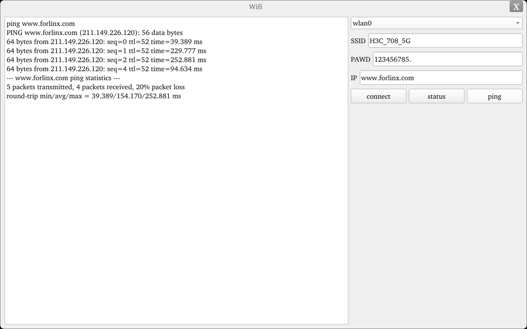
After a successful connection, set the IP and then click “ping” to perform a network test.
3.8 RTC Test
Note: Ensure that a button battery is installed on the board and the battery voltage is normal.
Icon:
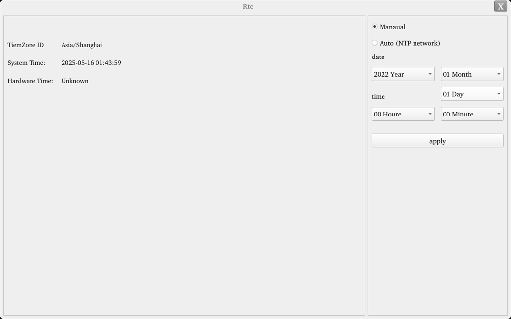
To test the RTC, configure the time via the test software, power cycle the device, and then re-run the software to confirm RTC synchronization.
Run the RTC test software to view and set the current system time, as shown below:
3.9 Key Test
Icon:
The “Keypad” is used to test the functionality of the built-in keys by verifying whether the corresponding key turns blue when pressed. The interface is shown below:
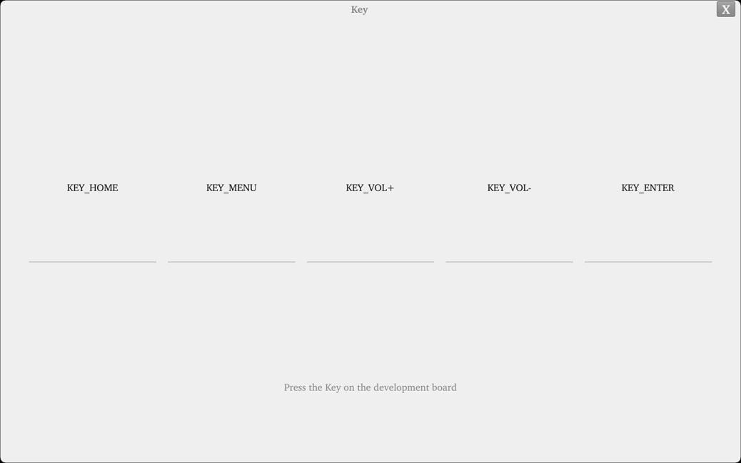
There are four physical keys KEY1, KEY2, KEY3, KEY4 on the side of the OK536 carrier board. When a key is pressed, the corresponding key in the test application will turn blue, indicating the key functions normally.
3.10 Watchdog Test
Icon:
“WatchDog” is an application used to test whether the watchdog function is normal. The interface is as follows:
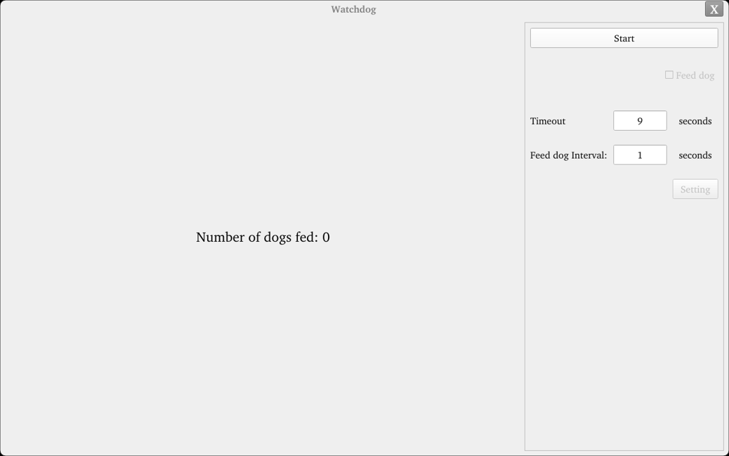
Check “feed dog”, click the “open watchdog” button, and the watchdog function will be started. The program will perform dog feeding operations, and normally the system will not reboot.
Uncheck “feed dog”, click the “open watchdog” button, and the watchdog function will be started. The program does not perform dog feeding operations. About 10 seconds after opening the watchdog, the system reboots, indicating the watchdog function is normal.
3.11 Ping Test
Icon:
“Ping” is an interface version of the commonly used network test command ping. The interface is as follows:
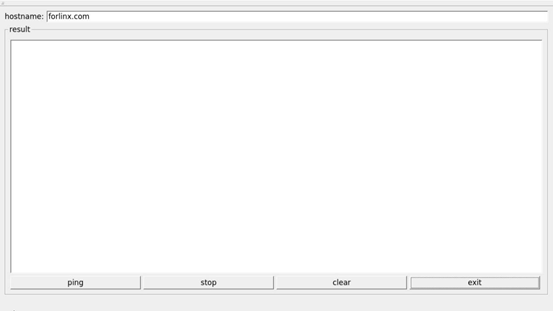
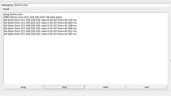
In the hostname field, write the target IP to ping. After clicking the “ping” button, the result field will show the ping result. Click stop to stop the ping test, and click “clear” to clear the information in result.
As shown in the figure, it indicates the network between them is smooth.
3.12 Backlight Test
Icon:
“BackLight” is an LCD backlight adjustment application. Adjust the progress bar left and right to adjust the backlight brightness. After opening, the interface is as follows:
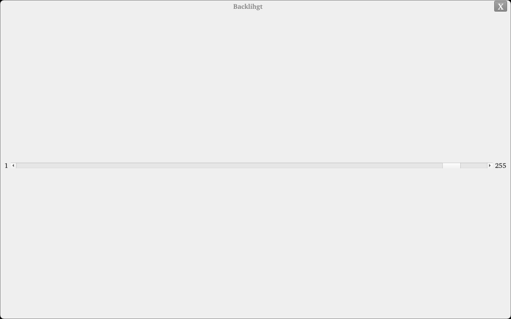
Drag the slider in the interface to set the LCD backlight brightness. 1 is the dimmest, 255 is the brightest. 0 needs to be set via the command line. Refer to “4.21 LCD Backlight Adjustment”.
3.13 Music Playback Test
Use the application icon “  ” to test music playback.
“musicplayer” is a simple audio test application that can be used to test whether the sound card functions normally and also serves as a simple audio player.
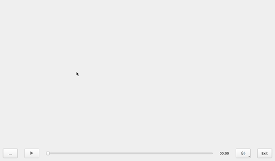
Application Interface
Click the button in the lower left corner and select the test audio /forlinx/audio/30s.mp3
3.14 CPU Frequency Configuration Test
The OK536 cpu0-cpu3 maximum main frequency is 1.6GHz. By default, the CPU dynamically adjusts the main frequency according to load, but it can also be set to a fixed CPU main frequency.
Click the desktop settings icon to enter the next-level menu:
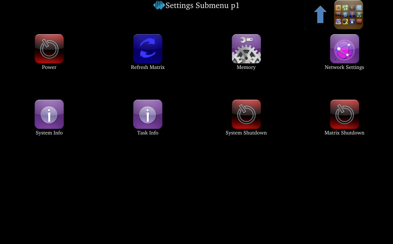
Click the icon to enter the CPU main frequency setting page.
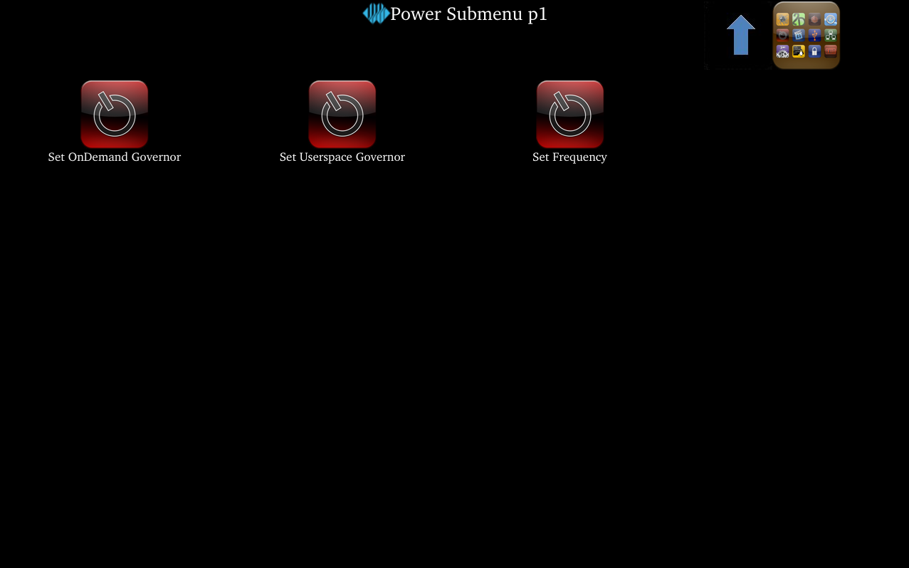
Set OnDemand Governor:Dynamically adjust the main clock on demand.
Set Userspace Governor:Set the main clock in user space.
Set Frequency CPU0-3:Set the small core main frequency.
Take setting the small core frequency as an example: First click “Set Userspace Governor”, click “RUN” in the pop-up dialog,
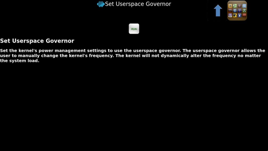
then click “Set Frequency CPU0-3” to set a fixed frequency. (Click the arrow in the upper right corner to return to the previous directory, click the icon in the upper right corner to return to the main directory).
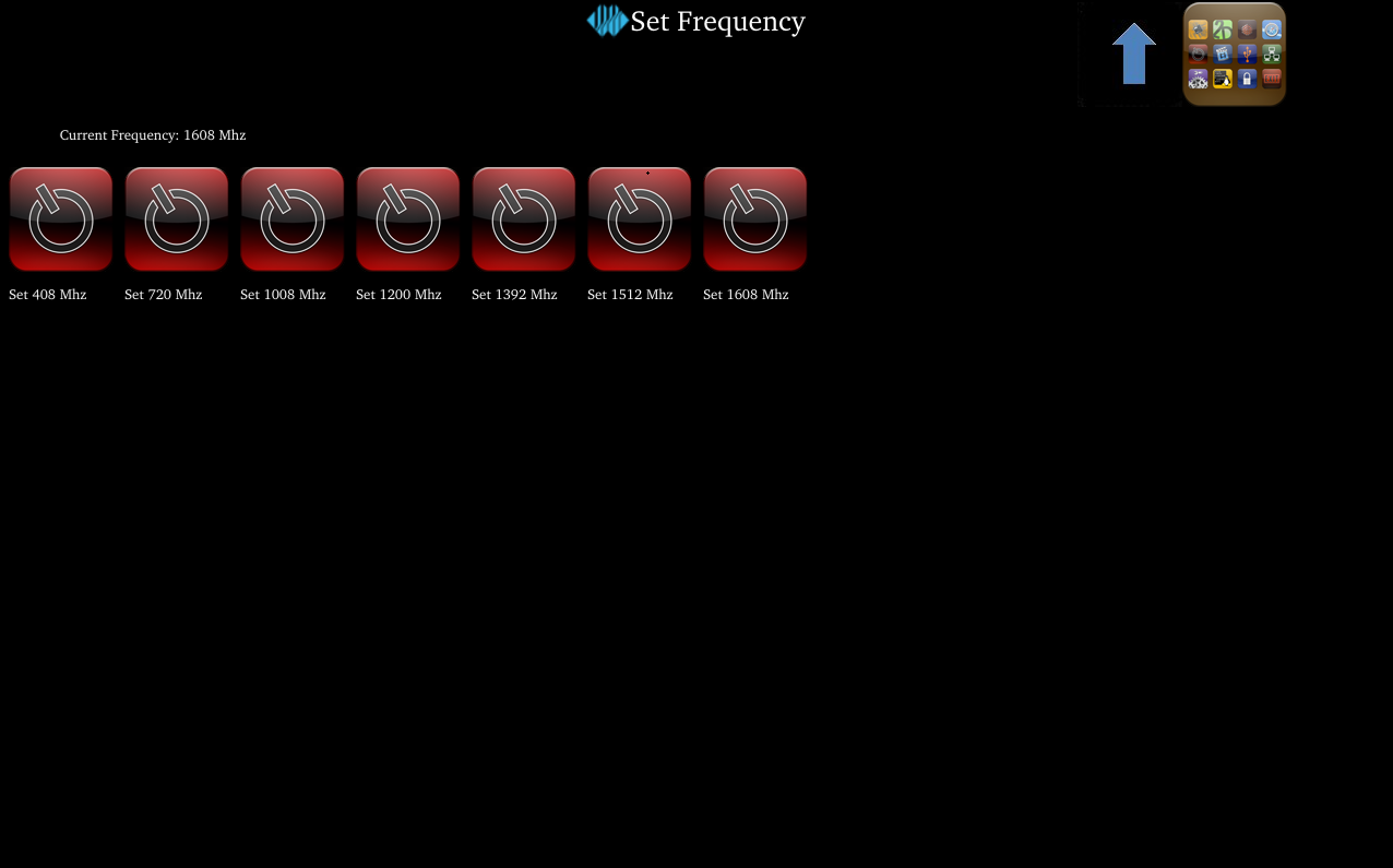
Select the corresponding frequency according to needs for setting.
3.15 SQLite3 Data Test
Icon:
Click the icon to enter the database test interface.
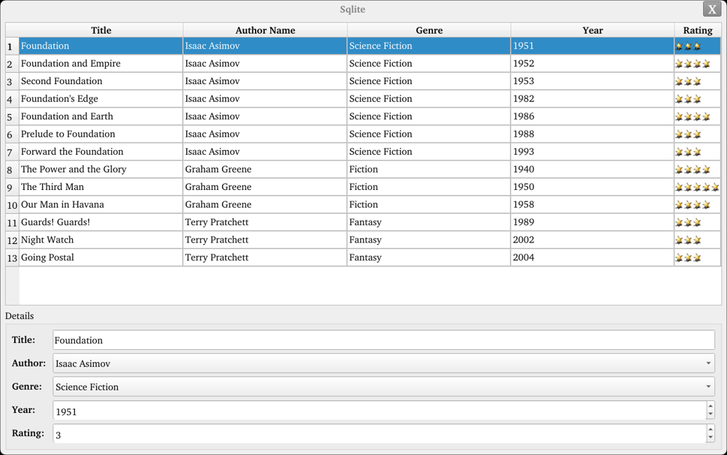
Select the row that needs to be modified, and you can modify the value of each column.
3.16 SPI Test
Icon:
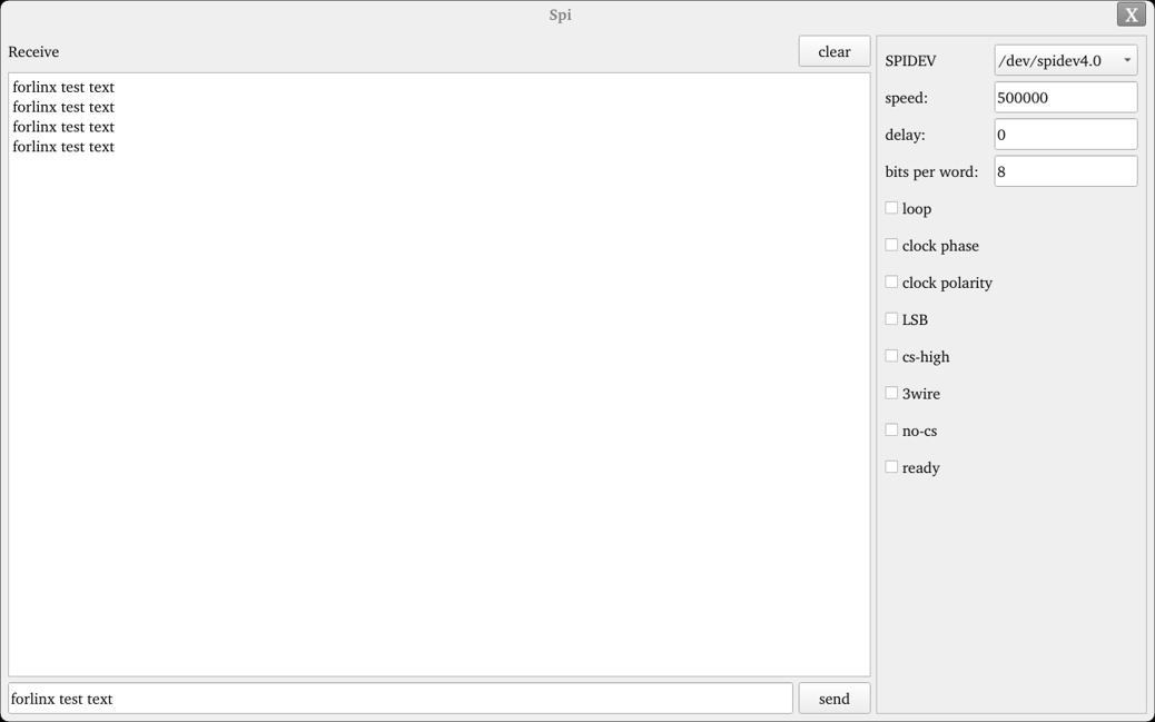
Click the icon to access the SPI test interface, select the device, short-circuit the MOSI and MISO pins, and click “Send” at the bottom to receive the transmitted data, thereby completing the test.
4. OK536-UP4 Command Line Function Test
The OK536-UP4 platform comes with a rich set of command-line tools for users to utilize.
Test program source code paths:
OK536-linux-sdk/buildroot/package/auto/forlinx/cmd_demo
OK536-linux-sdk/buildroot/package/forlinx/forlinx_cmd
Test program path: /usr/bin
4.1 System Information Query
To view kernel information, enter the following command:
root@OK536:/# uname -a
Linux OK536 5.10.198 #5 SMP PREEMPT Thu Feb 6 09:24:52 CST 2025 aarch64 GNU/Linux
To view CPU information:
root@OK536:/# cat /proc/cpuinfo
processor       : 0
BogoMIPS        : 48.00
Features        : fp asimd aes pmull sha1 sha2 crc32 atomics fphp asimdhp cpuid asimdrdm lrcpc dcpop asimddp
CPU implementer : 0x41
CPU architecture: 8
CPU variant     : 0x2
CPU part        : 0xd05
CPU revision    : 0

processor       : 1
BogoMIPS        : 48.00
Features        : fp asimd aes pmull sha1 sha2 crc32 atomics fphp asimdhp cpuid asimdrdm lrcpc dcpop asimddp
CPU implementer : 0x41
CPU architecture: 8
CPU variant     : 0x2
CPU part        : 0xd05
CPU revision    : 0

processor       : 2
BogoMIPS        : 48.00
Features        : fp asimd aes pmull sha1 sha2 crc32 atomics fphp asimdhp cpuid asimdrdm lrcpc dcpop asimddp
CPU implementer : 0x41
CPU architecture: 8
CPU variant     : 0x2
CPU part        : 0xd05
CPU revision    : 0

processor       : 3
BogoMIPS        : 48.00
Features        : fp asimd aes pmull sha1 sha2 crc32 atomics fphp asimdhp cpuid asimdrdm lrcpc dcpop asimddp
CPU implementer : 0x41
CPU architecture: 8
CPU variant     : 0x2
CPU part        : 0xd05
CPU revision    : 0
To view environment variable information:
root@OK536:/# env
SHELL=/bin/bash
EDITOR=/bin/vi
PWD=/root
LOGNAME=root
HOME=/root
QT_QPA_FB_DISABLE_INPUT=1
QT_QPA_PLATFORM=linuxfb
TERM=vt100
USER=root
SHLVL=1
QT_QPA_FONTDIR=/usr/share/fonts
QT_QPA_EVDEV_TOUCHSCREEN_PARAMETERS=/dev/input/ts:rotate=90:invertx
PATH=/bin:/sbin:/usr/bin:/usr/sbin
DBUS_SESSION_BUS_ADDRESS=unix:path=/var/run/dbus/system_bus_socket
QT_QPA_GENERIC_PLUGINS=evdevtouch:/dev/input/ts
_=/usr/bin/env
4.2 Frequency Test
Note: The T536 has four cores in total. This process uses cpu0 as an example for operation, but in reality, cpu0 to cpu3 will change simultaneously.
All cpufreq governor types supported in the current kernel:
root@OK536:/# cat /sys/devices/system/cpu/cpu0/cpufreq/scaling_available_governors
conservative ondemand userspace powersave performance schedutil
Among these, userspace represents user mode, which allows other user programs to adjust CPU frequency in this mode.
To view the current frequency levels supported by the CPU:
root@OK536:/# cat /sys/devices/system/cpu/cpu0/cpufreq/scaling_available_frequencies
408000 720000 1008000 1200000 1392000 1512000 1608000
Set to user mode and modify the frequency to 720000:
root@OK536:/# echo userspace > /sys/devices/system/cpu/cpu0/cpufreq/scaling_governor
root@OK536:/# echo 720000 > /sys/devices/system/cpu/cpu0/cpufreq/scaling_setspeed
To view the current frequency after modification:
root@OK536:/# cat /sys/devices/system/cpu/cpu0/cpufreq/cpuinfo_cur_freq
720000
4.3 Temperature Test
To view temperature values:
root@OK536:/# cat /sys/class/thermal/thermal_zone0/temp
48692
The temperature value is 48℃.
4.4 Watchdog Test
Watchdog is a commonly used function in embedded systems. The device node for the watchdog in OK536-UP4 is /dev/watchdog. The maximum watchdog timeout is 16 seconds.
Start the watchdog, set the reset time to 10s, and feed the dog regularly using fltest_watchdog. This command opens the watchdog and performs feeding operations, so the system will not reboot.
root@OK536:/#fltest_watchdog -t 10 -c
Watchdog Ticking Away!
When using Ctrl+C to end the test program, feeding stops, and the watchdog remains open. After 10s, the system resets.
If you do not want a reset, enter the command to close the watchdog within 10s after ending the program:
root@OK536:/# fltest_watchdog -d //Turn off the watchdog
Start the watchdog, set the reset time to 10s, and do not feed it.
This command opens the watchdog but does not perform feeding operations. The system will reboot after 10s.
root@OK536:/# fltest_watchdog -t 10
4.5 RTC Function Test
Note: Ensure that a button battery is installed on the board and the battery voltage is normal..
RTC testing mainly involves using the date and hwclock tools to set software and hardware times. The purpose is to test whether the software clock reads the RTC clock synchronously when the board is powered off and then back on. Then power off and on the board again. After entering the system, read the system time to confirm synchronization.
root@OK536:/# date -s "2023-08-01 15:16:30"                              // Set the system (software) time
Tue Aug  1 15:16:30 CST 2023
root@OK536:/# hwclock -u -w                                    // Synchronize the system time to the hardware clock (RTC)
root@OK536:/# hwclock -u -r                                                // Read and display the hardware clock time
Tue Aug  1 15:16:40 2023  0.000000 seconds
Then power off and power on the board. After entering the system, read the system time, and you can see that the time is synchronized.
root@OK536:/#date
Tue Aug  1 15:20:46 CST 2023
4.6 Key Test
There are eight buttons on the carrier board, five of which are located on the side: HOME, ENTER/MENU, VOL+, VOL- and GPIO KEY.
To test these five side keys, execute the following command:
root@OK536:~# fltest_keytest
key115 Presse
key115 Released
key114 Presse
key114 Released
key139 Presse
key139 Released
key28 Presse
key28 Released
key102 Presse
key102 Released
key148 Presse
key148 Released
4.7 485 & UART Test
The OK536-UP4 development board is equipped with 6 UART interfaces, which are distributed on the development board as follows:
UART |
Device Nodes |
Description |
|---|---|---|
UART4 |
/dev/ttyAS4 |
ttl serial port |
UART6 |
/dev/ttyAS6 |
485_0 |
UART11 |
/dev/ttyAS11 |
485_1 |
This test uses 485_0 and 485_1 for loopback testing. Connect 485_A0 to 485_A1 and 485_B0 to 485_B1.
Note: UART testing is similar to that of RS-485: the RX and TX pins are connected to other TTL serial ports, and commands are used to read and write data.
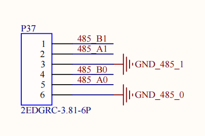
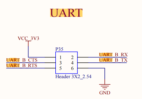
Enter the following command in the development board serial port:
root@OK536:/# fltest_uarttest -d /dev/ttyAS6 -b 115200 -r &
[1] 1953
root@OK536:/# fltest_uarttest -d /dev/ttyAS11 -b 115200 -w
tx_0: Gpi2GoMkYywl2IE9sEBcG6yI0DpmDbFT
rx_0: Gpi2GoMkYywl2IE9sEBcG6yI0DpmDbFT
[1]+  Done                    fltest_uarttest -d /dev/ttyAS8 -b 115200 -r
root@OK536:/#
4.8 GPADC Test
Three GPADC are routed out from the development board, with a voltage sampling range of 0–1.8 V. The sampling voltage is adjusted via the R357 potentiometer:
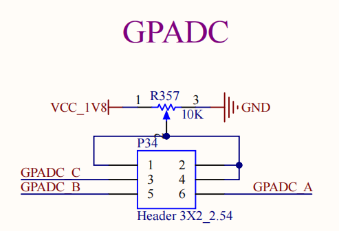
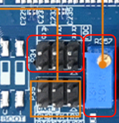
Taking GPADC_A as an example, short-circuit pins 1 and 6 on P34, run “fltest_adc”, enter 2, and read the event from “/dev/input/event2”, which corresponds to channel 7 of GPADC1.
root@OK536:~# fltest_adc
Available devices:
/dev/input/event2:      sunxi-gpadc1/channel7/input0
/dev/input/event3:      sunxi-gpadc1/channel8/input0
/dev/input/event4:      sunxi-gpadc1/channel9/input0
Select the device event number: 2
sunxi-gpadc1/channel7/input0
[12038.378921] sunxi:gpadc-2088000.gpadc:[INFO]: Enable channel 7
value 819 --- vol 359mv
value 823 --- vol 361mv
value 829 --- vol 364mv
4.9 TF Test
Note:
The SD card mount directory is /run/media, supporting hot plugging. The terminal will print information about the SD card;
NTFS format file systems are not supported. If unsure about the TF card format, it is recommended to format it to FAT32 before use.
Insert the TF card into the TF card slot on the development board carrier board. Under normal conditions, the development board terminal will print the following information:
[ 2829.588203] sunxi:sunxi_mmc_host-4020000.sdmmc:[INFO]: no vqmmc,Check if there is regulator
[ 2829.610087] sunxi:sunxi_mmc_host-4020000.sdmmc:[INFO]: sdc set ios:clk 400000Hz bm PP pm ON vdd 23 width 1 timing LEGACY(SDR12) dt B
[ 2829.636024] sunxi:sunxi_mmc_host-4020000.sdmmc:[INFO]: sdc set ios:clk 400000Hz bm PP pm ON vdd 23 width 1 timing LEGACY(SDR12) dt B
[ 2829.652328] sunxi:sunxi_mmc_host-4020000.sdmmc:[INFO]: sdc set ios:clk 400000Hz bm PP pm ON vdd 23 width 1 timing LEGACY(SDR12) dt B
[ 2829.667936] sunxi:sunxi_mmc_host-4020000.sdmmc:[INFO]: sdc set ios:clk 400000Hz bm PP pm ON vdd 23 width 1 timing LEGACY(SDR12) dt B
[ 2829.684228] sunxi:sunxi_mmc_host-4020000.sdmmc:[INFO]: sdc set ios:clk 400000Hz bm PP pm ON vdd 23 width 1 timing LEGACY(SDR12) dt B
[ 2829.846018] sunxi:sunxi_mmc_host-4020000.sdmmc:[INFO]: sdc set ios:clk 0Hz bm PP pm ON vdd 23 width 1 timing LEGACY(SDR12) dt B
[ 2829.858882] sunxi:sunxi_mmc_host-4020000.sdmmc:[INFO]: no vqmmc,Check if there is regulator
[ 2829.880794] sunxi:sunxi_mmc_host-4020000.sdmmc:[INFO]: sdc set ios:clk 400000Hz bm PP pm ON vdd 23 width 1 timing LEGACY(SDR12) dt B
[ 2829.903424] mmc1: host does not support reading read-only switch, assuming write-enable
[ 2829.913032] sunxi:sunxi_mmc_host-4020000.sdmmc:[INFO]: sdc set ios:clk 400000Hz bm PP pm ON vdd 23 width 4 timing LEGACY(SDR12) dt B
[ 2829.932021] sunxi:sunxi_mmc_host-4020000.sdmmc:[INFO]: sdc set ios:clk 400000Hz bm PP pm ON vdd 23 width 4 timing UHS-SDR104 dt B
[ 2829.945132] sunxi:sunxi_mmc_host-4020000.sdmmc:[INFO]: sdc set ios:clk 150000000Hz bm PP pm ON vdd 23 width 4 timing UHS-SDR104 dt B
[ 2829.958722] sunxi:sunxi_mmc_host-4020000.sdmmc:[INFO]: sdc set ios:clk 150000000Hz bm PP pm ON vdd 23 width 4 timing UHS-SDR104 dt B
[ 2829.972238] sunxi:sunxi_mmc_host-4020000.sdmmc:[INFO]: used kernel tuning, delay = 0
[ 2829.980930] sunxi:sunxi_mmc_host-4020000.sdmmc:[INFO]: change sample method
[ 2829.988728] sunxi:sunxi_mmc_host-4020000.sdmmc:[INFO]: start tuning, tuning clk = 150000000  opcode=19
[ 2829.999152] sunxi:sunxi_mmc_host-4020000.sdmmc:[INFO]: ----speed mode = 6
[ 2830.035337] sunxi:sunxi_mmc_host-4020000.sdmmc:[ERR]: wait dma hold bit clear timeout
[ 2830.061618] sunxi:sunxi_mmc_host-4020000.sdmmc:[ERR]: wait dma hold bit clear timeout
[ 2830.112611] sunxi:sunxi_mmc_host-4020000.sdmmc:[ERR]: wait dma hold bit clear timeout
[ 2830.126382] sunxi:sunxi_mmc_host-4020000.sdmmc:[INFO]: tuning section:
[ 2830.126388] sunxi:sunxi_mmc_host-4020000.sdmmc:[INFO]: [0-15|16]
[ 2830.133814] sunxi:sunxi_mmc_host-4020000.sdmmc:[INFO]: [21-55|35]
[ 2830.140639] sunxi:sunxi_mmc_host-4020000.sdmmc:[INFO]: [61-63|3]
[ 2830.147565] sunxi:sunxi_mmc_host-4020000.sdmmc:[INFO]:
[ 2830.160238] sunxi:sunxi_mmc_host-4020000.sdmmc:[INFO]: tuning result: 21 - 55,  best: 38
[ 2830.169349] mmc1: new ultra high speed SDR104 SDHC card at address e624
[ 2830.178573] mmcblk1: mmc1:e624 SL16G 14.8 GiB
[ 2830.190898]  mmcblk1: p1 p2 p3 p4 p5 p6 p7 p8
[ 2830.407046] squashfs: Unknown parameter 'umask'
[ 2830.434538] FAT-fs (mmcblk1p1): Volume was not properly unmounted. Some data may be corrupt. Please run fsck.
[ 2830.701242] EXT4-fs (mmcblk1p5): recovery complete
[ 2830.714497] EXT4-fs (mmcblk1p5): mounted filesystem with ordered data mode. Opts: (null)

root@OK536:/#
Check the mount directory:
root@OK536:/# ls /run/media                   //List the files in the /run/media directory
mmcblk0p1  mmcblk0p6  mmcblk1p1  mmcblk1p5
Write test:
root@OK536:/# dd if=/dev/zero of=/run/media/mmcblk1p1/test bs=1M count=500 conv=fsync
500+0 records in
500+0 records out
524288000 bytes (524 MB, 500 MiB) copied, 10.6269 s, 49.3 MB/s
Read test:
Note: To ensure the accuracy of the data, please restart the development board to test the reading speed.
root@OK536:/# dd if=/dev/mmcblk1p1 of=/dev/null bs=1M count=500 iflag=direct
500+0 records in
500+0 records out
524288000 bytes (524 MB, 500 MiB) copied, 7.56327 s, 69.3 MB/s
After using the TF card, you need to use umount to unmount the TF card before ejecting it.
root@OK536:/#umount /run/media/mmcblk1p1
Note: Exit the TF card mount path before removing the TF card.
4.10 Storage Test
The OK536-UP4 platform eMMC operates in HS400 mode by default. Below is a simple test of eMMC read/write speed using the ext4 file system as an example.
Write test:
root@OK536:/# dd if=/dev/zero of=/root/data.img bs=1M count=500 conv=fsync
500+0 records in
500+0 records out
524288000 bytes (524 MB, 500 MiB) copied, 5.00589 s, 105 MB/s
Read test:
Note: To ensure the accuracy of the data, please restart the development board to test the reading speed.
root@OK536:/# dd if=/root/data.img of=/dev/null bs=1M count=500 iflag=direct
500+0 records in
500+0 records out
524288000 bytes (524 MB, 500 MiB) copied, 2.25874 s, 232 MB/s
4.11 USB 2.0&3.0
**Note: **
The USB Type-C programming port is for programming purposes only;
Hot plugging of USB devices is supported;
NTFS format file systems are not supported. If unsure about the USB drive format, it is recommended to format it to FAT32 before use;
Note the difference between USB3.0 and USB2.0 interfaces.
The OK536 supports one USB 2.0 port and one USB 3.0 port.
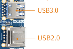
After booting the development board, connect a USB drive to the USB host interface on the board.
Serial port information:
[ 4998.259219] usb 3-1.4: new high-speed USB device number 5 using sunxi-ehci
[ 4998.480083] usb 3-1.4: New USB device found, idVendor=05e3, idProduct=0749, bcdDevice=15.35
[ 4998.489448] usb 3-1.4: New USB device strings: Mfr=3, Product=4, SerialNumber=5
[ 4998.497646] usb 3-1.4: Product: USB3.0 Card Reader
[ 4998.503021] usb 3-1.4: Manufacturer: Generic
[ 4998.507812] usb 3-1.4: SerialNumber: 000000001536
[ 4998.515477] usb-storage 3-1.4:1.0: USB Mass Storage device detected
[ 4998.523814] scsi host0: usb-storage 3-1.4:1.0
[ 4999.556889] scsi 0:0:0:0: Direct-Access     Generic  MassStorageClass 1536 PQ: 0 ANSI: 6
[ 4999.851113] sd 0:0:0:0: [sda] 31116288 512-byte logical blocks: (15.9 GB/14.8 GiB)
[ 4999.860847] sd 0:0:0:0: [sda] Write Protect is off
[ 4999.866396] sd 0:0:0:0: [sda] Mode Sense: 21 00 00 00
[ 4999.873344] sd 0:0:0:0: [sda] Write cache: disabled, read cache: enabled, doesn't support DPO or FUA
[ 4999.916627]  sda: sda1 sda2 sda3 sda4 sda5 sda6 sda7 sda8
[ 4999.927524] sd 0:0:0:0: [sda] Attached SCSI removable disk
[ 5000.267104] squashfs: Unknown parameter 'umask'
[ 5000.297860] FAT-fs (sda1): Volume was not properly unmounted. Some data may be corrupt. Please run fsck.
[ 5000.372506] EXT4-fs (sda5): recovery complete
[ 5000.377452] EXT4-fs (sda5): mounted filesystem with ordered data mode. Opts: (null)
Check the mount directory:
root@OK536:/#ls /run/media/
mmcblk0p1  mmcblk0p6  sda1
sda1 represents the first partition of the first inserted USB storage device, and so on.
Check USB drive contents:
root@OK536:/#ls -l /run/media/sda1
total 8
drwxrwx--- 2 root disk 8192 Sep 23  2021 'System Volume Information'
-rwxrwx--- 1 root disk    0 Apr 25 09:25  test
Write test: Write speed is limited by the specific storage device:
root@OK536:/# dd if=/dev/zero of=/run/media/sda1/test bs=1M count=500 conv=fsync
500+0 records in
500+0 records out
524288000 bytes (524 MB, 500 MiB) copied, 43.0038 s, 12.2 MB/s
Read test:
Note: To ensure the accuracy of the data, please restart the development board to test the reading speed.
root@OK536:/#dd if=/run/media/sda1/test of=/dev/null bs=1M count=500 iflag=direct
500+0 records in
500+0 records out
524288000 bytes (524 MB, 500 MiB) copied, 13.5184 s, 38.8 MB/s
After using the USB drive, use umount to unmount it before unplugging:
root@OK536:/#umount /run/media/sda1
Note: Exit the mount path before unplugging the USB drive.
4.12 Ethernet Configuration
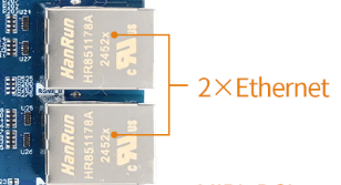
The OK536-UP4 features two onboard Gigabit Ethernet cards. When connected via network cables, the default configuration out-of-the-box sets eth0 to static IP 192.168.0.232 and eth1 to static IP 192.168.1.232. The network cards on OK536-UP4 can be configured via the /etc/network/interfaces configuration file.
4.12.1 Gigabit Ethernet Static IP Method
Note: The Gigabit Ethernet card in the kernel is eth0, with a default IP of 192.168.0.232.
After the development board powers on and boots normally, execute the following command to open the network configuration file /etc/network/interfaces:
root@OK536:/#vi /etc/network/interfaces
Content is as follows (there may be slight differences after software version updates; refer to actual information):
iface: Specifies the network interface requiring a static IP.
address: Specifies the IP address to be fixed.
netmask: Sets the subnet mask.
gateway: Specifies the gateway.
root@OK536:/# cat /etc/network/interfaces
# interface file auto-generated by buildroot

auto lo
iface lo inet loopback

auto eth0
iface eth0 inet static
address 192.168.0.232
netmask 255.255.255.0
gateway 192.168.0.1

auto eth1
iface eth1 inet static
address 192.168.1.232
netmask 255.255.255.0
gateway 192.168.1.1
root@OK536:/#
root@OK536:/#vi /etc/resolve.conf
Setnameserver
root@OK536:/#vi /etc/resolve.conf

nameserver  114.114.114.114
nameserver  8.8.8.8
After configuring according to actual needs, save and exit. Use sync to synchronize. The configuration will only take effect after restarting the development board or executing ip addr flush dev eth0 to clear the network card IP, followed by ifdown -a and ifup -a to restart the configuration.
4.12.2 Testing Ethernet Speed
Note:
Testing communication speed between the development board and a computer requires that the computer and development board can communicate normally;
This test assumes iperf3 tools are installed on Windows (3-tools\iperf-3.1.3-win64.zip).
Use the network speed testing tool iperf3 to test the eth0 network speed of the OK536-UP4 carrier board.
Run the following command in server mode using iperf3 in the Windows Command Prompt:
D:\iperf-3.1.3-win64\iperf-3.1.3-win64>iperf3.exe -s
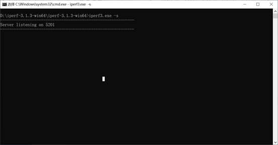
The IP address of eth0 on the development board is 192.168.1.11, and the IP address of the Windows computer is 192.168.1.39. Enter the following in the OK536 serial debugging terminal:
root@OK536:/# iperf3 -c 192.168.1.39            //Test upload bandwidth
Connecting to host 192.168.1.39, port 5201
[  5] local 192.168.1.11 port 55152 connected to 192.168.1.39 port 5201
[ ID] Interval           Transfer     Bitrate         Retr  Cwnd
[  5]   0.00-1.00   sec   113 MBytes   949 Mbits/sec    0    267 KBytes
[  5]   1.00-2.00   sec   113 MBytes   945 Mbits/sec    0    267 KBytes
[  5]   2.00-3.00   sec   112 MBytes   938 Mbits/sec    0    267 KBytes
[  5]   3.00-4.00   sec   113 MBytes   944 Mbits/sec    0    267 KBytes
[  5]   4.00-5.00   sec   112 MBytes   939 Mbits/sec    0    267 KBytes
[  5]   5.00-6.00   sec   113 MBytes   946 Mbits/sec    0    267 KBytes
[  5]   6.00-7.00   sec   112 MBytes   938 Mbits/sec    0    267 KBytes
[  5]   7.00-8.00   sec   112 MBytes   942 Mbits/sec    0    267 KBytes
[  5]   8.00-9.00   sec   112 MBytes   943 Mbits/sec    0    267 KBytes
[  5]   9.00-10.00  sec   112 MBytes   938 Mbits/sec    0    267 KBytes
- - - - - - - - - - - - - - - - - - - - - - - - -
[ ID] Interval           Transfer     Bitrate         Retr
[  5]   0.00-10.00  sec  1.10 GBytes   942 Mbits/sec    0             sender
[  5]   0.00-10.00  sec  1.10 GBytes   941 Mbits/sec                  receiver

iperf Done.
root@OK536:/# iperf3 -c 192.168.1.39 -R            //Test download bandwidth
Connecting to host 192.168.1.39, port 5201
Reverse mode, remote host 192.168.1.39 is sending
[  5] local 192.168.1.11 port 40676 connected to 192.168.1.39 port 5201
[ ID] Interval           Transfer     Bitrate
[  5]   0.00-1.00   sec   112 MBytes   941 Mbits/sec
[  5]   1.00-2.00   sec   112 MBytes   941 Mbits/sec
[  5]   2.00-3.00   sec   112 MBytes   941 Mbits/sec
[  5]   3.00-4.00   sec   112 MBytes   942 Mbits/sec
[  5]   4.00-5.00   sec   112 MBytes   942 Mbits/sec
[  5]   5.00-6.00   sec   112 MBytes   941 Mbits/sec
[  5]   6.00-7.00   sec   112 MBytes   941 Mbits/sec
[  5]   7.00-8.00   sec   112 MBytes   940 Mbits/sec
[  5]   8.00-9.00   sec   112 MBytes   941 Mbits/sec
[  5]   9.00-10.00  sec   112 MBytes   941 Mbits/sec
- - - - - - - - - - - - - - - - - - - - - - - - -
[ ID] Interval           Transfer     Bitrate
[  5]   0.00-10.00  sec  1.10 GBytes   945 Mbits/sec                  sender
[  5]   0.00-10.00  sec  1.10 GBytes   941 Mbits/sec                  receiver

iperf Done.
root@OK536:/#
4.13 Network Services
Note: The default IP for eth0 is 192.168.0.232.
4.13.1 Web Service
Note: The PC’s IP must be in the same subnet as the development board’s IP for normal operation.
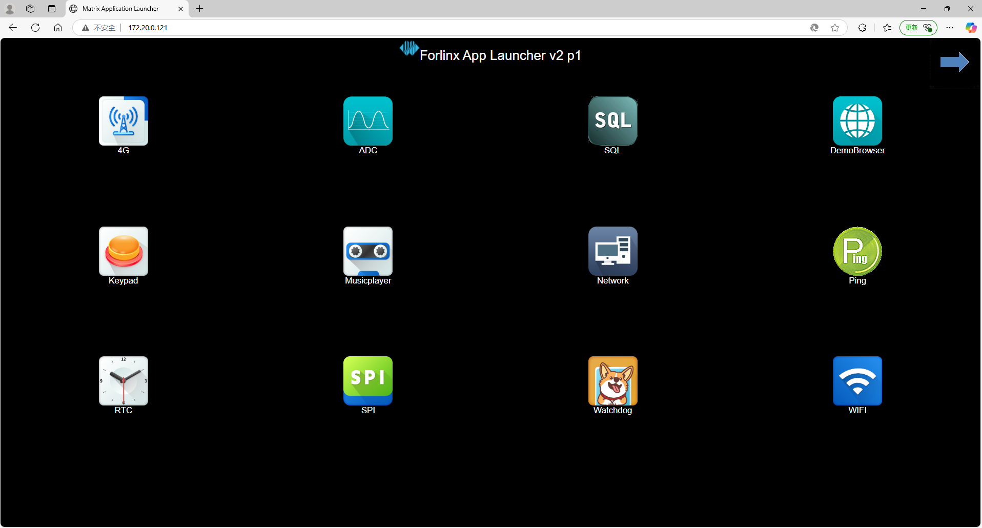
The OK536-UP4 development board comes pre-installed with a lighttpd web server, and the service starts automatically at system boot. Enter the development board’s IP address in a browser to access the web pages on the board’s web server, as shown below:
4.13.2 SFTP
Installation package path: 3-tools\FileZilla*
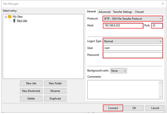
The OK536-UP4 development board supports SFTP service, which is automatically enabled at system startup. Once the IP address is configured, it can function as an SFTP server. The following describes how to utilize the SFTP tool for file transfer.
Install the FileZilla tool on Windows and configure it by following the steps shown in the image below.
Open the filezilla tool, click File, and select Site Manager.
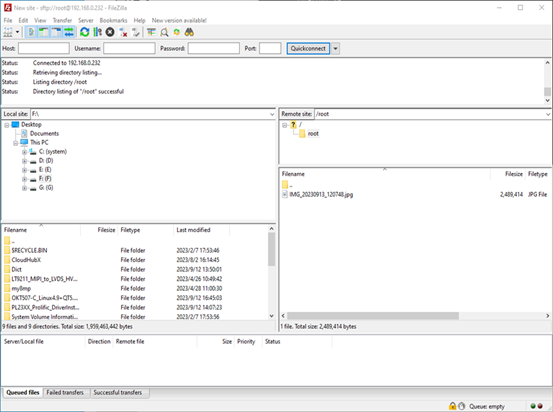
After successful login, upload and download operations can be performed.
4.14 WiFi Test
4.14.1 STA Modes
Note:
Due to varying network environments, please configure according to your actual situation when conducting this experiment;
The development board supports connecting to 2.4G and 5G wireless hotspots.
This mode acts as a station to connect to the wireless network. In the following test, the router uses WPA encryption, and the connected Wi-Fi is 2.4GHz with the hotspot name: H3C_708 and password: 123456785. Due to varying network environments, please configure according to your actual situation during this test.
Enter the following command in the development board terminal:
The meanings of relevant parameters in the command are as follows:
Parameter |
Meaning |
|---|---|
-i |
Wireless network card node name |
-s |
The actual Wi-Fi hotspot name to connect to. |
-p |
The parameter following -p refers to the password of the actual Wi-Fi hotspot to connect to; if the hotspot has no password, write NONE after -p. |
Serial port prints as follows:
root@OK536:/# fltest_wifi.sh -i wlan0 -s H3C_708 -p 123456785.
[  204.803506] sunxi-gmac 4500000.gmac0 eth0: Link is Down
wifi wlan0
ssid H3C_708
pasw 123456785.
waiting...
[  211.388935] IPv6: ADDRCONF(NETDEV_CHANGE): wlan0: link becomes ready
udhcpc: started, v1.35.0
udhcpc: broadcasting discover
udhcpc: broadcasting discover
udhcpc: broadcasting select for 192.168.1.20, server 192.168.1.1
udhcpc: lease of 192.168.1.20 obtained from 192.168.1.1, lease time 86400
deleting routers
adding dns 192.168.1.1
connect ok
Check whether you can ping an external network. Enter the following command in the terminal:
root@OK536:/#ping -I wlan0 baidu.com -c 4            //Specify the wlan0 network interface and ping it four times
PING baidu.com (110.242.68.66): 56 data bytes
64 bytes from 110.242.68.66: seq=0 ttl=54 time=95.213 ms
64 bytes from 110.242.68.66: seq=1 ttl=54 time=119.289 ms
64 bytes from 110.242.68.66: seq=2 ttl=54 time=40.234 ms
64 bytes from 110.242.68.66: seq=3 ttl=54 time=64.454 ms

--- baidu.com ping statistics ---
4 packets transmitted, 4 packets received, 0% packet loss
round-trip min/avg/max = 40.234/79.797/119.289 ms
4.14.2 AP Mode
Note:
Before testing, ensure the Gigabit Ethernet interface (eth0) is connected and the network is functioning properly;
5 GHz hotspot enabled by default;
To enable the 2.4GHz hotspot and modify the/usr/bin/fltest _ hostap. sh, change “hostapd/etc/hostapd-5g.conf &” to “hostapd/etc/hostapd-2.4g.conf &”.
Configure the hotspot:
WiFi hotspot: OK536_WIFI_5G_AP
Password:12345678
The hotspot name and password can be found in the /etc/hostapd-5g.conf file.
root@OK536:/# fltest_hostap.sh
done!
uap0: interface state UNINITIALIZED->COUNTRY_UPDATE
[   74.247545] IPv6: ADDRCONF(NETDEV_CHANGE): uap0: link becomes ready
uap0: interface state COUNTRY_UPDATE->ENABLED
uap0: AP-ENABLED
uap0: STA 86:de:12:63:58:96 IEEE 802.11: authenticated
uap0: STA 86:de:12:63:58:96 IEEE 802.11: associated (aid 1)
uap0: AP-STA-CONNECTED 86:de:12:63:58:96
uap0: STA 86:de:12:63:58:96 WPA: pairwise key handshake completed (RSN)
uap0: EAPOL-4WAY-HS-COMPLETED 86:de:12:63:58:96
4.15 4G Test
Note: The driver supports the Quectel EC20 4G module.
The OK536 supports the 4G module. Insert the 4G module before starting the development board, install the 4G antenna, insert the SIM card, start the development board, and perform dial-up Internet access operations for the EC20.
4.15.1 EC20 Module Test
Note:
When using an IoT card for testing, confirm the module firmware version; lower versions may not support it and require an upgrade of the EC20 firmware;
Some IoT cards require a dedicated account and password for dial-up; please adjust the command based on your actual situation;
You can use the quectelCM –help command to view the meanings of related parameters.
After connecting the module and powering on the development board and module, you can check the USB status using the lsusb command.
root@OK536:/# lsusb
Bus 002 Device 001: ID 1d6b:0001 Linux Foundation 1.1 root hub
Bus 001 Device 001: ID 1d6b:0002 Linux Foundation 2.0 root hub
Bus 004 Device 001: ID 1d6b:0001 Linux Foundation 1.1 root hub
Bus 003 Device 003: ID 2c7c:0125 Quectel Wireless Solutions Co., Ltd. EC25 LTE modem //EC20
Bus 003 Device 002: ID 1a40:0101 Terminus Technology Inc. Hub
Bus 003 Device 001: ID 1d6b:0002 Linux Foundation 2.0 root hub
Check the device node status under /dev.
root@OK536:/#ls /dev/ttyUSB*
/dev/ttyUSB0  /dev/ttyUSB1  /dev/ttyUSB2  /dev/ttyUSB3
After successful device identification, you can perform dial-up Internet access testing;
root@OK536:/#quectelCM &
Print information as follows:
[01-01_00:33:21:301] Quectel_QConnectManager_Linux_V1.6.0.15
[01-01_00:33:21:309] Find /sys/bus/usb/devices/3-1.1 idVendor=0x2c7c idProduct=0x125, bus=0x003, dev=0x003
[01-01_00:33:21:309] Auto find qmichannel = /dev/qcqmi0
[01-01_00:33:21:309] Auto find usbnet_adapter = usb0
[01-01_00:33:21:310] netcard driver = GobiNet, driver version = V1.6.2.14
[01-01_00:33:21:310] ioctl(0x89f3, qmap_settings) failed: Operation not supported, rc=-1
[01-01_00:33:21:310] Modem works in QMI mode
[01-01_00:33:21:327] Get clientWDS = 7
[01-01_00:33:21:360] Get clientDMS = 8
[01-01_00:33:21:391] Get clientNAS = 9
[01-01_00:33:21:423] Get clientUIM = 10
[01-01_00:33:21:455] Get clientWDA = 11
[01-01_00:33:21:487] requestBaseBandVersion EC20CEHDLGR08A05M1G
[01-01_00:33:21:615] requestGetSIMStatus SIMStatus: SIM_READY
[01-01_00:33:21:647] requestGetProfile[1] cmnet///0
[01-01_00:33:21:679] requestRegistrationState2 MCC: 460, MNC: 0, PS: Attached, DataCap: LTE
[01-01_00:33:21:712] requestQueryDataCall IPv4ConnectionStatus: DISCONNECTED
[01-01_00:33:21:71[ 2001.950466] IPv6: ADDRCONF(NETDEV_CHANGE): usb0: link becomes ready
2] ifconfig usb0 0.0.0.0
[01-01_00:33:21:721] ifconfig usb0 down
[01-01_00:33:21:808] requestSetupDataCall WdsConnectionIPv4Handle: 0x87669020
[01-01_00:33:21:968] ifconfig usb0 up
[01-01_00:33:21:977] udhcpc -f -n -q -t 5 -i usb0
udhcpc: started, v1.35.0
udhcpc: broadcasting discover
udhcpc: broadcasting select for 10.32.26.177, server 10.32.26.178
udhcpc: lease of 10.32.26.177 obtained from 10.32.26.178, lease time 7200
[01-01_00:33:22:158] deleting routers
[01-01_00:33:22:185] adding dns 111.11.1.3
[01-01_00:33:22:185] adding dns 111.11.11.3
If an IP is automatically assigned and DNS is added, the EC20 dial-up is successful.
After successful dial-up, check the network node via ifconfig as usb0 (the node name may vary; refer to the actual situation), and test network status via the ping command.
root@OK536:/# ping -I usb0 baidu.com -c4
PING baidu.com (110.242.68.66): 56 data bytes
64 bytes from 110.242.68.66: seq=0 ttl=53 time=59.096 ms
64 bytes from 110.242.68.66: seq=1 ttl=53 time=69.325 ms
64 bytes from 110.242.68.66: seq=2 ttl=53 time=69.955 ms
64 bytes from 110.242.68.66: seq=3 ttl=53 time=83.063 ms

--- baidu.com ping statistics ---
4 packets transmitted, 4 packets received, 0% packet loss
round-trip min/avg/max = 59.096/70.359/83.063 ms
4.16 Playback/Recording Test
Note: The OK536-UP4 features 1 x 3.5mm audio jack and 1 x XH-2.54-2PS speaker interface. The headphone microphone can be used for recording.
Playback test:
root@OK536:/# aplay /forlinx/audio/30s.wav          //Headphone audio playback.
root@OK536:/# mpg123 /forlinx/audio/30s.mp3         //Headphone audio playback.
Recording test:
root@OK536:/# arecord -c2 -r 48000 -f S16_LE -d 3 mic.wav
Recording WAVE 'mic.wav' : [ 4608.610608] [SNDCODEC][sunxi_card_hw_params][630]:stream_flag: 1
Signed 16 bit Little Endian, Rate 48000 Hz, Stereo
4.17 LCD Backlight Adjustment
The brightness range for the backlight is (0–255), where 255 indicates the highest brightness and 0 turns off the backlight. Enter the following command in the terminal after system startup for backlight testing.
Check the current screen backlight value:
root@OK536:~# cat /sys/class/backlight/backlight0/brightness
200                                         //The current backlight level is 200
Turn off the backlight:
root@OK536:~# echo 0 > /sys/class/backlight/backlight0/brightness //Turn off the backlight
Turn on the LCD backlight:
root@OK536:~# echo 125 > /sys/class/backlight/backlight0/brightnes //Set the backlight level to 125
4.18 Closing Desktop
root@OK536:/# /etc/init.d/S60Matrix_Browser stop                      //Close the desktop
root@OK536:/# fbinit 0                                               //Screen Clear Operation
cleanning /dev/fb0 ...
clean /dev/fb0 finish
4.19 LED Test
There is a controllable blue LED light on the SoM. When the board powers on and starts, this blue LED flashes. There is a blue LED light on the carrier board, which is not lit by default.
SoM LED test method as follows:
View the trigger condition.
root@OK536:/# cat /sys/class/leds/heartbeat/trigger
none rc-feedback rfkill-any rfkill-none timer [heartbeat] mmc0 mmc1 mmc2 rfkill0 rfkill2
Here, [heartbeat] indicates the current trigger condition is the system heartbeat light. Writing the above string to trigger can modify the trigger condition.
User control
When the LED trigger condition is set to none, you can control the LED on/off via commands.
root@OK536:/# echo none > /sys/class/leds/heartbeat/trigger
root@OK536:/# echo 1 > /sys/class/leds/heartbeat/brightness
root@OK536:/# echo 0 > /sys/class/leds/heartbeat/brightness
Change the blue LED to heartbeat mode.
root@OK536:/# echo heartbeat > /sys/class/leds/heartbeat/trigger
The LED is now controlled by the system clock, flashing in a certain rhythm.
The carrier board LED test method is same:
root@OK536:~# echo 1 > /sys/class/leds/led1/brightness      //Turn on
root@OK536:~# echo 0 > /sys/class/leds/led1/brightness      //Turn off
root@OK536:~# echo 1 > /sys/class/leds/led2/brightness      //Turn on
root@OK536:~# echo 0 > /sys/class/leds/led2/brightness      //Turn off
4.20 SQLite3 Test
SQLite3 is a lightweight database system, an ACID-compliant relational database management system with low resource consumption. The OK536-UP4 development board uses version 3.38.5 of SQLite3.
root@OK536:/# sqlite3
SQLite version 3.38.5 2022-05-06 15:25:27
Enter ".help" for usage hints.
Connected to a transient in-memory database.
Use ".open FILENAME" to reopen on a persistent database.

sqlite> create table tbl1 (one varchar(10), two smallint);        // Create table 'tbl1'
sqlite> insert into tbl1 values('hello!',10);                     // Insert data: hello!|10
sqlite> insert into tbl1 values('goodbye', 20);                   // Insert data: goodbye|20
sqlite> select * from tbl1;                                       // Query all contents of tbl1
hello!|10
goodbye|20
sqlite> delete from tbl1 where one = 'hello!';                    // Delete data where 'one' equals 'hello!'
sqlite> select * from tbl1;                                       // Query all contents again
goodbye|20
sqlite> .quit                                                     // Exit the database (or use .exit)
root@OK536:/#
4.21 Adding a Startup Script
4.21.1 Temporarily Adding a Startup Script
First, create a shell script:
root@OK536:/# vi /autorun.sh
Modify the file reference as follows (users need to modify according to their actual situation):
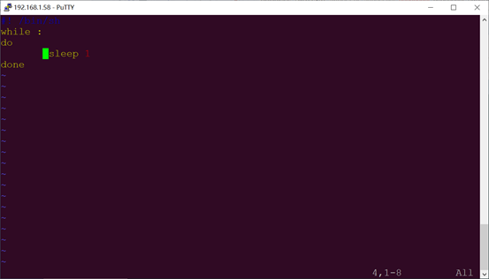
After modification, save and exit, then add execution permission to the script;
root@OK536:/#chmod +x /autorun.sh
Add the following at the end of the /etc/init.d/rcS file:
/autorun.sh &
Save the changes and exit.
4.21.2 Adding a Startup Script to the Flashing Image
To add a startup script when flashing the image, modifications need to be made in the development environment source code. The operation method is as follows:
Enter the OK536-linux-sdk source code package, and create an autorun.sh file at the path: buildroot/package/auto/forlinx/root.
Content format reference as follows; please modify according to your actual needs:
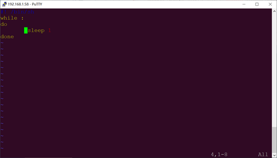
Use the chmod +x autorun.sh command to add execution permission to the file.
Add the following at the end of the buildroot/package/auto/forlinx/root/etc/init.d/rcS file:
/autorun.sh &
Save the changes and exit.
Recompile and package
Please refer to the “Linux5.10.198_Compilation” section of the “Linux 5.10.198 User Compilation Manual”; further details will not be provided here.
4.22 A55 Dhrystone Test
Dhrystone is a comprehensive benchmark program designed in 1984 by Reinhold P. Weicker to test CPU (integer) computing performance. Dhrystone does not include floating-point operations. Its output result is the number of times Dhrystone runs per second, i.e., the number of iterations of the main loop per second.
The Dhrystone test program has been successfully ported to the OK536-UP4 platform. You can use the following command to conduct the test.
Set the CPU to high-performance mode
root@OK536:/# echo performance > /sys/devices/system/cpu/cpu0/cpufreq/scaling_governor
Dhrystone test
root@ OK536:/# echo 50000000 | dhrystone        //Run the Dhrystone test 50,000,000 times

Dhrystone Benchmark, Version 2.1 (Language: C)

Program compiled without 'register' attribute

Please give the number of runs through the benchmark:
Execution starts, 50000000 runs through Dhrystone
Execution ends

Final values of the variables used in the benchmark:

Int_Glob:            5
        should be:   5
Bool_Glob:           1
        should be:   1
Ch_1_Glob:           A
        should be:   A
Ch_2_Glob:           B
        should be:   B
Arr_1_Glob[8]:       7
        should be:   7
Arr_2_Glob[8][7]:    50000010
        should be:   Number_Of_Runs + 10
Ptr_Glob->
  Ptr_Comp:          514008000
        should be:   (implementation-dependent)
  Discr:             0
        should be:   0
  Enum_Comp:         2
        should be:   2
  Int_Comp:          17
        should be:   17
  Str_Comp:          DHRYSTONE PROGRAM, SOME STRING
        should be:   DHRYSTONE PROGRAM, SOME STRING
Next_Ptr_Glob->
  Ptr_Comp:          514008000
        should be:   (implementation-dependent), same as above
  Discr:             0
        should be:   0
  Enum_Comp:         1
        should be:   1
  Int_Comp:          18
        should be:   18
  Str_Comp:          DHRYSTONE PROGRAM, SOME STRING
        should be:   DHRYSTONE PROGRAM, SOME STRING
Int_1_Loc:           5
        should be:   5
Int_2_Loc:           13
        should be:   13
Int_3_Loc:           7
        should be:   7
Enum_Loc:            1
        should be:   1
Str_1_Loc:           DHRYSTONE PROGRAM, 1'ST STRING
        should be:   DHRYSTONE PROGRAM, 1'ST STRING
Str_2_Loc:           DHRYSTONE PROGRAM, 2'ND STRING
        should be:   DHRYSTONE PROGRAM, 2'ND STRING

Microseconds for one run through Dhrystone:    0.1
Dhrystones per Second:                      9208103.0
4.23 View Chip-ID
Input in the serial debugging terminal:
root@OK536:~# cat /sys/class/sunxi_info/sys_info
[11484.968475] sunxi:sunxi_sidget_soc_ver_regs() +267: Failed to find "soc_id" in dts.
sunxi_platform    : T536
sunxi_secure      : normal
sunxi_serial      : 0c84220b00c6542800002c0000000000
sunxi_chiptype    : 00005100
sunxi_batchno     : 0x19120001
sunxi_soc_ver    : 0x1
4.24 CAN Test
There are 2 x CANFD, which are led out to the P23 socket.
Short-circuit H, L, and GND of can0 and can1 respectively to perform the test.
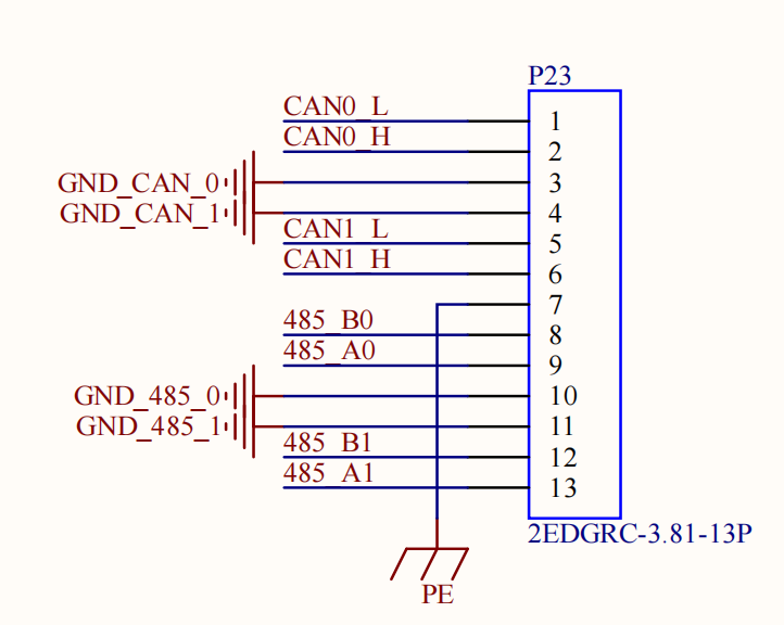
CAN FD Testing
Start CAN FD service.
root@OK536:~# ip link set can0 down
root@OK536:~# ip link set can1 down
root@OK536:~# ip link set can0 up type can bitrate 500000 sample-point 0.8 dbitrate 2000000 dsample-point 0.75 fd on
[11819.880401] IPv6: ADDRCONF(NETDEV_CHANGE): can1: link becomes ready
root@OK536:~# ip link set can1 up type can bitrate 500000 sample-point 0.8 dbitrate 2000000 dsample-point 0.75 fd on
[11825.354308] IPv6: ADDRCONF(NETDEV_CHANGE): can2: link becomes ready
root@OK536:~# ip link set dev can0 txqueuelen 4096
root@OK536:~# ip link set dev can1 txqueuelen 4096
Configure CAN1 for receiving and CAN2 for transmission.
root@OK536:~# candump -td can0 &
[2] 13067
root@OK536:~# cangen can1
 (000.000000)  can1  7B5   [5]  87 62 BE 22 BB
 (000.200138)  can1  263   [8]  70 79 E5 78 56 2C AF 77
 (000.200083)  can1  2EA   [8]  2C 05 AB 5F C6 31 18 26
 (000.199968)  can1  37E   [2]  C6 C7
 (000.200121)  can1  514   [5]  54 1E A1 7B 46
CAN
Start CAN service.
root@OK536:~# ip link set can1 down
[12184.278335] here is close.
root@OK536:~# ip link set can0 down
root@OK536:~# ip link set can1 up type can bitrate 1000000
[12191.442280] IPv6: ADDRCONF(NETDEV_CHANGE): can2: link becomes ready
root@OK536:~# ip link set can0 up type can bitrate 1000000
[12195.450213] IPv6: ADDRCONF(NETDEV_CHANGE): can1: link becomes ready
Configure CAN2 for receiving and CAN1 for transmission.
root@OK536:~# candump can1 &
[2] 13271
root@OK536:~# cangen can0
  can2  45D   [8]  0B E7 A6 7A 38 7E E7 4B
  can2  194   [8]  F8 7A BA 0D 5E 6C 1B 7B
  can2  26E   [8]  F2 1F 34 7D 41 1C 83 26
  can2  365   [8]  84 FE A2 06 FD 2A 87 2C
  can2  2F8   [8]  B1 33 39 32 F5 F2 47 53
4.25 SPI Test
There is a spi2, spi3 led out from the carrier board, which is on the P32, P31 terminal.
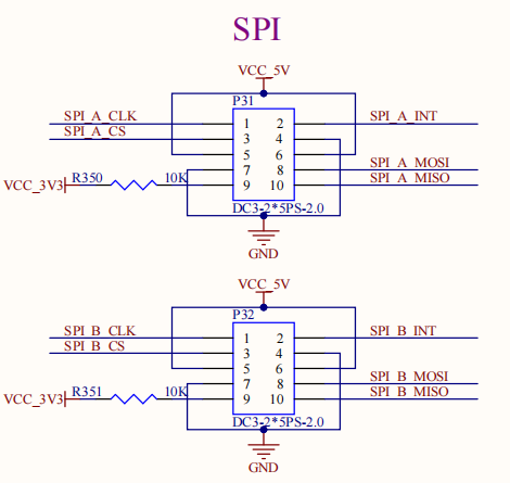
Short-circuit SPI_B_MOSI and SPI_B_MISO for testing
root@OK536:~# fltest_spidev_test -D /dev/spidev2.0
spi mode: 0
bits per word: 8
max speed: 500000 Hz (500 KHz)

FF FF FF FF FF FF
40 00 00 00 00 95
FF FF FF FF FF FF
FF FF FF FF FF FF
FF FF FF FF FF FF
DE AD BE EF BA AD
F0 0D
4.26 GPIO Test
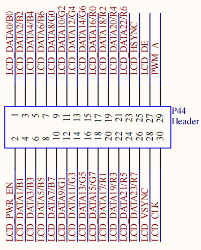
Taking PB14 as an example, the GPIO number is (A-1)*32+nr, where A is 2 and nr is 14, so the number is 46.
Set as Output.
root@OK536:/# echo 46 > /sys/class/gpio/export
root@OK536:/# echo out > /sys/class/gpio/gpio46/direction
root@OK536:/# echo 1 > /sys/class/gpio/gpio46/value      //Output high level
root@OK536:/# echo 0 > /sys/class/gpio/gpio46/value      //Output low level
root@OK536:/# echo 46 > /sys/class/gpio/unexport
Set as Input.
root@OK536:/# echo 46 > /sys/class/gpio/export
root@OK536:/# echo in > /sys/class/gpio/gpio46/direction
root@OK536:/# cat /sys/class/gpio/gpio46/value             //Pin left floating
1
root@OK536:/# cat /sys/class/gpio/gpio46/value      //Short-circuit pin 7 of P46
0
root@OK536:/# echo 46 > /sys/class/gpio/unexport
4.27 Bluetooth Testing
The OK536-UP4 carrier board AW-CM358 module integrates Bluetooth. This section demonstrates file transfer between a mobile phone/PC and the development board via Bluetooth.
Bluetooth Configuration
root@OK536:/# bluetoothctl                             // Open the BlueZ Bluetooth control utility
Agent registered
[CHG] Controller E8:FB:1C:66:FA:A6 Pairable: yes
[bluetooth]# power on          // Enable the Bluetooth controller
[CHG] Controller E8:FB:1C:66:FA:A6 Class: 0x00100000
Changing power on succeeded
[CHG] Controller E8:FB:1C:66:FA:A6 Powered: yes
[bluetooth]# pairable on       // Set the controller to be pairable
Changing pairable on succeeded
[bluetooth]# discoverable on   // Set the controller to be discoverable
Changing discoverable on succeeded
[CHG] Controller E8:FB:1C:66:FA:A6 Discoverable: yes
[bluetooth]# agent on        // Enable the Agent (for handling pairing requests)
Agent is already registered
[bluetooth]# default-agent    // Set the current agent as the default agent
Default agent request successful
[bluetooth]#
Board Passive Pairing (Standard pairing process).
After the above settings, open your computer and search for Bluetooth. Click “Add Bluetooth or Other Devices”, and a device named “OKT536” will appear. Click on this Bluetooth to attempt pairing,
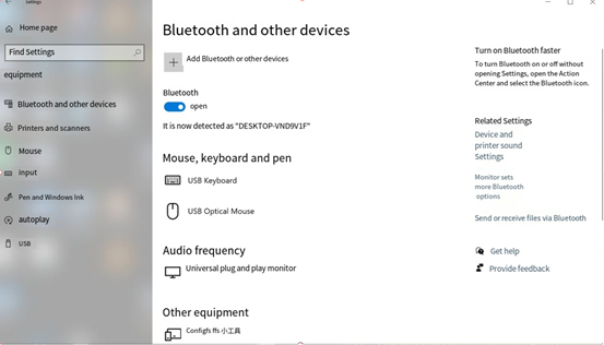
The print information on the development board is as follows. Enter “yes”:
[CHG] Device 2C:DB:07:C7:4F:F6 Connected: yes
Request confirmation
[agent] Confirm passkey 153732 (yes/no): yes
View and remove connected devices:
[bluetooth]# devices                                           //View connected Bluetooth devices
Device 2C:DB:07:C7:4F:F6 DESKTOP-VND9V1F
[bluetooth]# remove 2C:DB:07:C7:4F:F6                         //Remove the device
[DEL] Device 2C:DB:07:C7:4F:F6 DESKTOP-VND9V1F
Device has been removed
Active pairing of development board
In addition to passive pairing, it is also possible to send an active pairing request from the development board terminal.
[bluetooth]# scan on        //Turn on the scanning
Discovery started
[CHG] Controller E8:FB:1C:66:FA:A6 Discovering: yes
[NEW] Device 7B:01:59:ED:69:50 7B-01-59-ED-69-50
[NEW] Device 7C:71:13:5F:A3:8F 7C-71-13-5F-A3-8F
[NEW] Device 14:16:9E:62:39:BD zzy
[NEW] Device 2C:DB:07:C7:4F:F6 DESKTOP-VND9V1F  //Find the device you want to pair with
[CHG] Device 14:16:9E:62:39:BD RSSI: -74
[bluetooth]# scan off        //Turn off the scanning
Discovery stopped
[CHG] Device 2C:DB:07:C7:4F:F6 TxPower is nil
[CHG] Device 2C:DB:07:C7:4F:F6 RSSI is nil
[CHG] Device 14:16:9E:62:39:BD RSSI is nil
[CHG] Device 7C:71:13:5F:A3:8F TxPower is nil
[CHG] Device 7C:71:13:5F:A3:8F RSSI is nil
[CHG] Device 7B:01:59:ED:69:50 RSSI is nil
[CHG] Controller E8:FB:1C:66:FA:A6 Discovering: no
[bluetooth]# pair 2C:DB:07:C7:4F:F6        //Pair with a specified device
Attempting to pair with 14:16:9E:62:39:BD
[CHG] Device 14:16:9E:62:39:BD Connected: yes
Request confirmation
[agent] Confirm passkey 807166 (yes/no): yes        //Confirmation key
[CHG] Device 14:16:9E:62:39:BD Modalias: bluetooth:v000Fp1200d1436
[CHG] Device 14:16:9E:62:39:BD UUIDs: 00001105-0000-1000-8000-00805f9b34fb
......
[CHG] Device 14:16:9E:62:39:BD UUIDs: fa88c0d0-afac-11de-8a99-0800200c9a67
[CHG] Device 14:16:9E:62:39:BD ServicesResolved: yes
[CHG] Device 14:16:9E:62:39:BD Paired: yes
Pairing successful
[CHG] Device 14:16:9E:62:39:BD ServicesResolved: no
[CHG] Device 14:16:9E:62:39:BD Connected: no
[bluetooth]#
At the same time, a pairing request appears on the computer interface. Click “pairing”, and enter “yes” on the board to confirm. The pairing is successful.
Development board receives files
After successful pairing, on the computer side, you can use Bluetooth to send files to the board side.
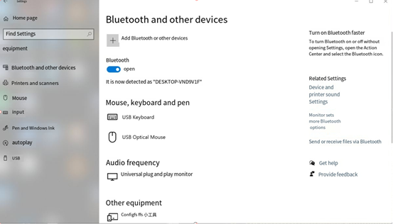
Click “Send or receive files via Bluetooth”.
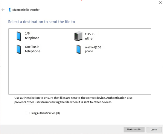
Select OKT536.
Select the file to send.
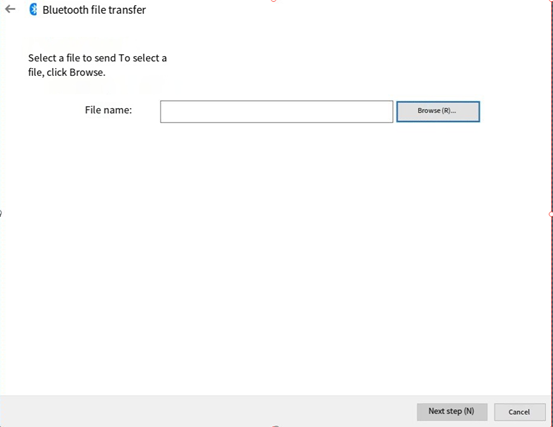
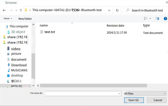
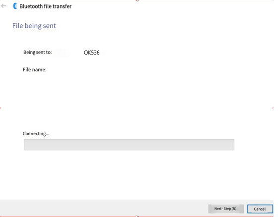
Waiting for sending to complete.
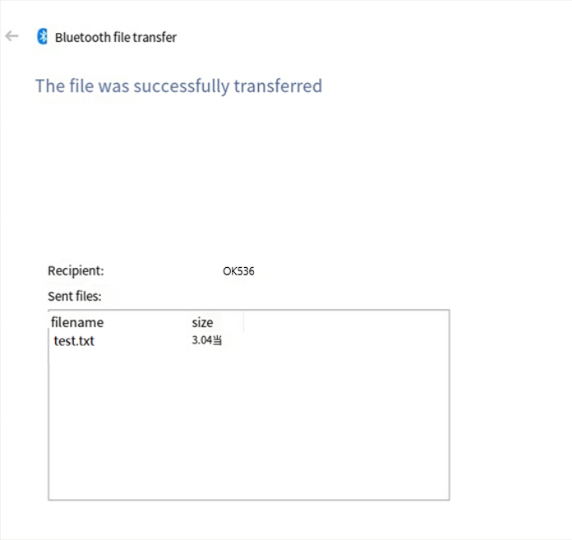
The received file is saved in the /tmp directory.
Send files from the development board
Similarly, you can use the development board to send files to the computer.
The test method is as follows:
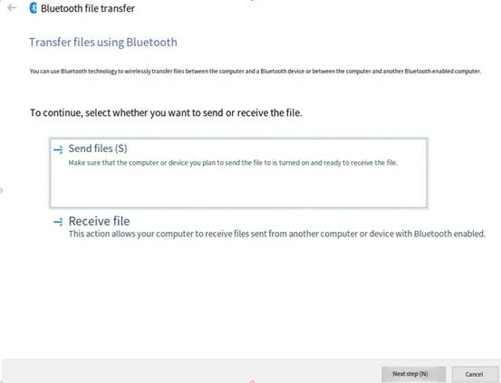
Select “Receive File” on the computer side.
root@OK536:~# bluetoothctl
Agent registered
[CHG] Controller E8:FB:1C:66:FA:A6 Pairable: yes
[bluetooth]# paired-devices        //View paired devices
Device 2C:DB:07:C7:4F:F6 DESKTOP-VND9V1F
[bluetooth]# exit
root@OK536:~# obexctl
[NEW] Client /org/bluez/obex
[obex]# connect   2C:DB:07:C7:4F:F6     //Link to a specific device
Attempting to connect to 2C:DB:07:C7:4F:F6
[NEW] Session /org/bluez/obex/client/session0 [default]
[NEW] ObjectPush /org/bluez/obex/client/session0
Connection successful
[2C:DB:07:C7:4F:F6]# send /run/media/mmcblk0p1/bootlogo.bmp  //Send file
Attempting to send /run/media/mmcblk0p1/bootlogo.bmp to /org/bluez/obex/client/session0
[NEW] Transfer /org/bluez/obex/client/session0/transfer0
Transfer /org/bluez/obex/client/session0/transfer0
Status: queued
Name: bootlogo.bmp
Size: 1339239
Filename: /run/media/mmcblk0p1/bootlogo.bmp
Session: /org/bluez/obex/client/session0
[CHG] Transfer /org/bluez/obex/client/session0/transfer0 Status: active
[CHG] Transfer /org/bluez/obex/client/session0/transfer0 Transferred: 65433 (@65KB/s 00:19)
[CHG] Transfer /org/bluez/obex/client/session0/transfer0 Transferred: 130961 (@65KB/s 00:18)
.....
[CHG] Transfer /org/bluez/obex/client/session0/transfer0 Status: complete
[DEL] Transfer /org/bluez/obex/client/session0/transfer0
[2C:DB:07:C7:4F:F6]# exit
The computer will receive the incoming file request for file transfer.
4.28 NPU Test
The OK536N-UP4 is integrated with the 2Tops NPU.
The NPU test routines are located as follows:
root@OK536:# cd /etc/npu/yolov5
root@OK536:/etc/npu/yolov5# ls
input_data  model  yolov5
Perform the NPU test:
root@OK536:/etc/npu/yolov5# ./yolov5 model/yolov5.nb input_data/dog.jpg
./yolov5 nbg input
VIPLite driver software version 2.0.3.2-AW-2024-08-30
viplite init OK.
VIPLite driver version=0x00020003...
VIP cid=0x1000003b, device_count=1
* device[0] core_count=1
awnn_init total: 3.73 ms.
  vip_create_network model/yolov5.nb: 26.16 ms.
input 0 dim 640 640 3 1, data_format=2, name=input[0], elements=16846849, scale=0.003922, zero_point=0
create input buffer 0: 1228800
output 0 dim 85 80 80 3 1, data_format=0, name=uid_5_out_0ub_uid_1_out_0, elements=1632000, none-quant
create output buffer 0: 6528000
output 1 dim 85 40 40 3 1, data_format=0, name=uid_4_out_0ub_uid_1_out_0, elements=408000, none-quant
create output buffer 1: 1632000
output 2 dim 85 20 20 3 1, data_format=0, name=uid_3_out_0ub_uid_1_out_0, elements=102000, none-quant
create output buffer 2: 408000
memory pool size=8161024 bytes
  load_param model/yolov5.nb: 6.76 ms.
  prepare network model/yolov5.nb: 5.57 ms.
  set network io model/yolov5.nb: 0.01 ms.
awnn_create total: 38.60 ms.
yolov5_preprocess.cpp run.
memcpy(0x7f82dce000, 0x7f8147b010, 1228800)  load_input_data: 0.97 ms.
  vip_flush_buffer input: 0.07 ms.
awnn_set_input_buffers total: 1.13 ms.
  vip_run_network: 29.75 ms.
  vip_flush_buffer output: 0.01 ms.
    fp32 6528000 memcpy: 71.26 ms.
    fp32 1632000 memcpy: 17.75 ms.
    fp32 408000 memcpy: 4.48 ms.
  tensor to fp: 93.66 ms.
awnn_run total: 123.48 ms.
yolov5_postprocess.cpp run.
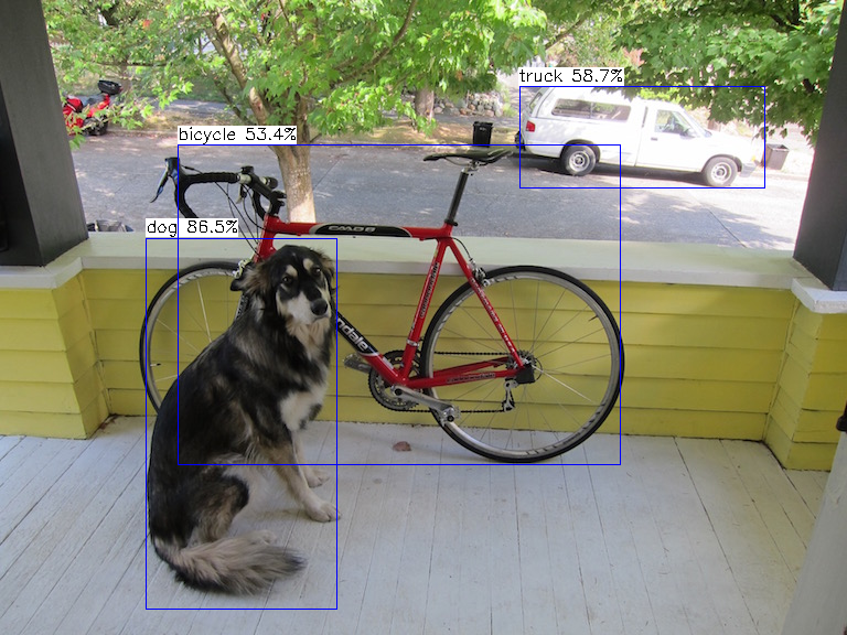
detection num: 3
16:  87%, [ 132,  216,  306,  552], dog
 7:  59%, [ 471,   78,  694,  171], truck
 1:  53%, [ 161,  131,  563,  423], bicycle
awnn_destroy total: 7.53 ms.
awnn_uninit total: 0.55 ms.
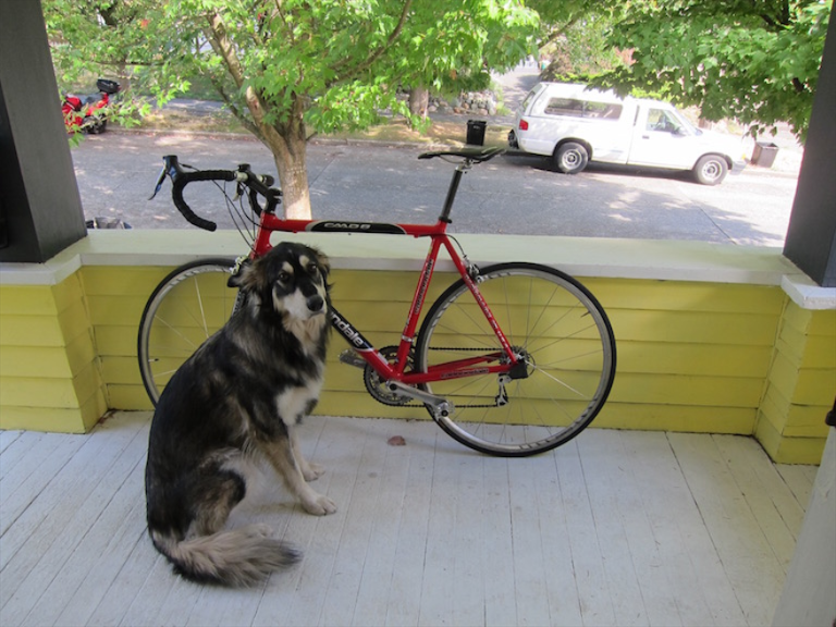
Test picture:
Output picture:
4.29 G2D Test
g2d test version:V2.1.20220906
================Usage================
g2d_test 1        means: 1*2560x1440 nv21 decompose to 4*720p nv21
g2d_test 2        means: 4*720 nv21 compose to 1*2560x1440 nv21
g2d_test 3        means: 1280x720 nv21 rotate to 720x1280 nv21
g2d_test 4        means: 1024x600 nv21 horizontal flips
g2d_test 5        means: 1024x600 nv21 vertical flips
================usage================
Picture rotation is demonstrated here. The program reads/forlinx/g2d _ test/1280x720 _ nv21.yuv and outputs it to/tmp/720x1280 _ rotate _ 90/720x1280 _ rotate _ 90.yuv after rotation.
root@OK536:~# fltest_g2dtest 3
g2d test version:V2.1.20220906
01-01 00:07:51.373 g2d_test(D) : arc=2, testid=3
01-01 00:07:51.374 suxiMemInterface(D) : sdk_memory version:V2.1.20220906
DEBUG  : ionAlloc <__GetIonMemOpsS:866>: *** get __GetIonMemOpsS ***
DEBUG  : cedarc <VeInitialize:1587>: ve init
DEBUG  : cedarc <veEnvInit:110>: VeContext 0x55ab7430e0, encoder 0, decodec 1
INFO   : cedarc <veEnvInit:138>: open /dev/cedar_dev fd = 3
DEBUG  : cedarc <veEnvInit:149>: get ve_reg_addr = 0x7f99226000
DEBUG  : cedarc <veEnvGetIcVersion:260>: ** address_macc 0x7f99226000 ve_top_offset = 0x800
DEBUG  : cedarc <veEnvGetIcVersion:318>: *** ic_version = 0x1001000021322
DEBUG  : cedarc <checkFeatureSupport:1412>: bEnableVcuFuncFlag = 0, nEncoderFlag = 0
DEBUG  : cedarc <VeInitialize:1640>: address_macc = 0x7f99226000, address_vetop = 0x7f99226800
DEBUG  : cedarc <getSocInfo:1205>: not exist SocInfo plugin, use SocInfo node
DEBUG  : cedarc <getSocInfo:1293>: ve_default_freq = 0
INFO   : cedarc <VeInitialize:1643>: *** ic_version = 0x1001000021322,
DEBUG  : cedarc <VeInitialize:1683>: *** nPhyOffset = 0x0
DEBUG  : ionAlloc <ion_create_context:172>: pid: 950, g_context = 0x55ab743280
DEBUG  : cedarc <CdcIonOpen:302>: open ion, file_name = /dev/dma_heap/system
DEBUG  : ionAlloc <ion_alloc_palloc_base:382>: ion alloc fd:4 size:1382400 heap:1, falgs:3
DEBUG  : ionAlloc <ion_alloc_palloc_base:426>: alloc succeed, addr_phy: 0xfee00000, addr_vir: 0x7f98b84000, size: 1382400 dma_buf_fd 5
01-01 00:07:51.376 g2d_test(D) : fopen /forlinx/g2d_test/1280x720_nv21.yuv OK
01-01 00:07:51.385 g2d_test(D) : alloc m_DispMemOps0.ion_buffer.fd_data.aw_fd=5
DEBUG  : ionAlloc <__GetIonMemOpsS:866>: *** get __GetIonMemOpsS ***
DEBUG  : ionAlloc <ion_alloc_open:233>: ion context already create, ref_count:2
DEBUG  : ionAlloc <ion_alloc_palloc_base:382>: ion alloc fd:4 size:1382400 heap:1, falgs:3
DEBUG  : ionAlloc <ion_alloc_palloc_base:426>: alloc succeed, addr_phy: 0xfec00000, addr_vir: 0x7f98a32000, size: 1382400 dma_buf_fd 6
01-01 00:07:51.387 g2d_test(D) : alloc m_DispMemOps.ion_buffer.fd_data.aw_fd=6
01-01 00:07:51.387 (D) : libsdk_g2d version:V2.2.20240304
01-01 00:07:51.387 g2d_test(D) : ================== start yuv rotate =============
01-01 00:07:51.389 g2d_test(D) : g2d rotate ret:0, use time =1732 us
01-01 00:07:51.389 g2d_test(D) : WritePicFileContent size=1382400
01-01 00:07:51.389 g2d_test(D) : fopen /tmp/720x1280_rotate_90.yuv OK
Before rotation:

After rotation:

4.30 Sleep Wakeup
Enter freeze or mem into/sys/power/state to sleep.
root@OK536:~# echo mem > /sys/power/state
[   29.353999] PM: suspend entry (deep)
[   29.360218] Filesystems sync: 0.002 seconds
[   29.366075] Freezing user space processes ... (elapsed 0.001 seconds) done.
[   29.375262] OOM killer disabled.
[   29.378906] Freezing remaining freezable tasks ... (elapsed 0.001 seconds) done.
[   29.388421] printk: Suspending console(s) (use no_console_suspend to debug)
Press pwron to wake up.
[   29.397451] rtc-rx8010 5-0032: Frequency stop detected
[   29.398917] dwmac-sunxi 4510000.ethernet eth1: Link is Down
[   29.400480] dwmac-sunxi 4510000.ethernet eth1: Link is Up - 1Gbps/Full - flow control rx/tx
[   29.400503] dwmac-sunxi 4510000.ethernet eth1: Link is Down
[   29.400598] sunxi:stmmac-4510000.ethernet:[INFO]: suspend finish 0
[   29.401732] dwmac-sunxi 4500000.ethernet eth0: Link is Down
[   29.403244] dwmac-sunxi 4500000.ethernet eth0: Link is Up - 1Gbps/Full - flow control rx/tx
[   29.403264] dwmac-sunxi 4500000.ethernet eth0: Link is Down
[   29.403356] sunxi:stmmac-4500000.ethernet:[INFO]: suspend finish 0
......
[   33.099183] sunxi:sunxi_mmc_host-4020000.sdmmc:[INFO]: [12-48|37]
[   33.105891] sunxi:sunxi_mmc_host-4020000.sdmmc:[INFO]: [52-63|12]
[   33.112831] sunxi:sunxi_mmc_host-4020000.sdmmc:[INFO]:
[   33.125654] sunxi:sunxi_mmc_host-4020000.sdmmc:[INFO]: tuning result: 12 - 48,  best: 30
[   33.908372] dwmac-sunxi 4510000.ethernet eth1: Link is Up - 1Gbps/Full - flow control rx/tx
[   36.821798] axp2202-aldo1: disabling
[   36.825982] axp2202-cldo4: disabling
[   36.830292] axp2202-vmid: disabling
5. OK536-UP4 Platform Multimedia Testing
5.1 OV5645 / OV13855 Capture Testing
Note: Before testing, refer to the “Closing Desktop” section to stop the desktop program and clear the screen.
There are 3 x MIPI CSI interfaces on the development board located in P6 P7 P8, appearing as /dev/video0, /dev/video4, /dev/video8. Taking the OV13855 as an example, when testing the OV5645, use the OV13855 as a reference and simply change the device node name to /dev/video4 or /dev/video8.
Camera Preview
root@OK536:~# gst-launch-1.0 v4l2src device=/dev/video0  !  video/x-raw,format=NV21, width=1920,height=1080 ! videoconvert !  kmssink
Setting pipeline to PAUSED ...
[   54.971834] [drm] [LVDS]sunxi_lvds_connector_get_modes start
[   54.978279] [drm] [LVDS]sunxi_lvds_connector_get_modes start
[   54.984714] [drm] [LVDS]sunxi_lvds_connector_get_modes start
[   54.991121] [drm] [LVDS]sunxi_lvds_connector_get_modes start
[   54.998346] PWR_ON!
[   55.032456] sensor_init
[   55.035413] eRet:0, 0x300a:0x0, times_out:3
[   55.260283] eRet:0, 0x300b:0xd8, times_out:3
Pipeline is live and does not ne[   55.486706] sunxi:vin:[ERR]: v4l2 sub device scaler get_selection error!
ed PREROLL ...
Pipeline is PREROLLED ...
Setting pipeline to PLAYING ...
New clock: GstSystemClock
[   55.508025] sensor_s_stream on = 1, 2112*1568 fps: 30 code: 3007
Redistribute latency...
0:00:03.6 / 99:99:99.
Collect 20 frames of data and save them to a file.
root@OK536:~# gst-launch-1.0 v4l2src device=/dev/video0 num-buffers=20 ! video/x-raw,format=NV12 , width=1920,height=1080 ! filesink location=/tmp/frame.yuv
Setting pipeline to PAUSED ...
[   97.697628] PWR_ON!
[   97.734099] sensor_init
[   97.737054] eRet:0, 0x300a:0x0, times_out:3
[   97.962023] eRet:0, 0x300b:0xd8, times_out:3
Pipeline is live and does not ne[   98.188259] sunxi:vin:[ERR]: v4l2 sub device scaler get_selection error!
ed PREROLL ...
Pipeline is PRER[   98.200058] sunxi:vin:[ERR]: buffer count is invalid, set to 3
OLLED ...
Setting pipeline to PLAYING ...
New clock: GstSystemClock
[   98.213152] sensor_s_stream on = 1, 2112*1568 fps: 30 code: 3007
Redistribute latency...
Got EOS from element "pipeline0".
Execution ended after 0:00:01[   99.214108] sensor_s_stream on = 0, 2112*1568 fps: 30 code: 3007
.022327875
Setting pipeline to NULL ...
[   99.228366] PWR_OFF!
Freeing pipeline ...
5.2 USB Camera Test
**Preview **
root@OK536:~# gst-launch-1.0 v4l2src device=/dev/video1  !  video/x-raw, width=1280,height=720 ! videoconvert !  kmssink
Setting pipeline to PAUSED ...
[  259.897453] [drm] [LVDS]sunxi_lvds_connector_get_modes start
[  259.903907] [drm] [LVDS]sunxi_lvds_connector_get_modes start
[  259.910297] [drm] [LVDS]sunxi_lvds_connector_get_modes start
[  259.916686] [drm] [LVDS]sunxi_lvds_connector_get_modes start
[  260.288841] usb 1-1.3: reset high-speed USB device number 3 using xhci-hcd
Pipeline is live and does not need PREROLL ...
Pipeline is PREROLLED ...
Setting pipeline to PLAYING ...
New clock: GstSystemClock
Redistribute latency...
0:00:13.1 / 99:99:99.
5.3 Video Encoding
MJPEG encoding
root@OK536:~# gst-launch-1.0 v4l2src device=/dev/video0 num-buffers=300 ! video/x-raw,format=NV12,framerate=30/1,width=1920,height=1080 ! omxmjpegvideoenc ! avimux ! filesink location=/mnt/UDISK/output_test.avi
Setting pipeline to PAUSED ...
DEBUG  : cedarc <CdcIniParserIni[   29.026353] sunxi:VE:[INFO]: 635 enable_cedar_hw_clk():
t:41>: load conf file /etc/cedar[   29.034875] sunxi:VE:[INFO]: 641 enable_cedar_hw_clk(): execute set_vcu_en_regmode_to1_to0
c.conf ok!
......
DEBUG  : omx_venc <__AwOmxVencGetParameter:868>:  get_parameter: width = 1920, height = 1080, stride = 1920, align = 16.
DEBUG  : omx_venc <__AwOmxVencGetParameter:878>:  get_parameter: width = 176, height = 144, stride = 0.
DEBUG  : cedarc <VeSetSpeed:2218>: *** set ve freq to 400 Mhz ***
DEBUG  : ionAlloc <ion_alloc_open:233>: ion context already create, ref_count:2
DEBUG  : cedarc <JpegEncOpen:1505>: init mutex_overlay
INFO   : cedarc <log_setlevel:63>: Set log level to 5 from /vendor/etc/cedarc.conf
ERROR  : cedarc <getDefaultParameter:35>: getDefaultParameter. UnsupportedIndex 100663312. unkonwn param 0x7fa35fd688

Redistribute latency...
0:00:07.1 / 99:99:99.
H.264 encoding
root@OK536:~# gst-launch-1.0 v4l2src device=/dev/video0 num-buffers=300 ! video/x-raw,format=NV12,framerate=30/1,width=1280,height=720 ! omxh264videoenc ! filesink location=/mnt/UDISK/output.h264
Setting pipeline to PAUSED ...
DEBUG  : cedarc <CdcIniParserIni[  221.148334] sunxi:VE:[INFO]: 635 enable_cedar_hw_clk():
t:41>: load conf file /etc/cedar[  221.156881] sunxi:VE:[INFO]: 641 enable_cedar_hw_clk(): execute set_vcu_en_regmode_to1_to0
c.conf ok!
......
DEBUG  : cedarc <VeInitialize:1748>: *** nPhyOffset = 0x0
DEBUG  : cedarc <VeSetSpeed:2218>: *** set ve freq to 400 Mhz ***
DEBUG  : ionAlloc <ion_alloc_open:233>: ion context already create, ref_count:2
INFO   : cedarc <log_setlevel:63>: Set log level to 5 from /vendor/etc/cedarc.conf
ERROR  : cedarc <getDefaultParameter:35>: getDefaultParameter. UnsupportedIndex 100663312. unkonwn param 0x7f90b8a688

Redistribute latency...
0:00:08.2 / 99:99:99.
5.4 Video Decoding
MJPEG decoding
root@OK536:~# gst-launch-1.0 filesrc location=/mnt/UDISK/output_test.avi ! decodebin ! filesink location=/mnt/UDISK/mjpeg.yuv
Setting pipeline to PAUSED ...
Pipeline is PREROLLING ...
DEBUG  : cedarc <CdcIniParserIni[  363.750819] sunxi:VE:[INFO]: 635 enable_cedar_hw_clk():
t:41>: load conf file /etc/cedar[  363.759384] sunxi:VE:[INFO]: 641 enable_cedar_hw_clk(): execute set_vcu_en_regmode_to1_to0
c.conf ok!
......
WARNING: cedarc <InitializeVideoDecoder:727>: warning: the nDisplayHoldingFrameBufferNum is 0
Pipeline is PREROLLED ...
Setting pipeline to PLAYING ...
New clock: GstSystemClock
Redistribute latency...
Got EOS from element "pipeline0".
MJPEG 1080p decoding, with the output format being YV12. Decoding requires 16-byte alignment; for example, for a resolution of 1920×1080, the YV12 data is 1920×1088, which includes cropping information. When previewing the file, the data must be cropped to output the valid data, gst-launch-1.0 filesrc location=/mnt/UDISK/mjpeg.yuv ! rawvideoparse format=yv12 width=1920 height=1088 ! videocrop top=0 bottom=8 ! videoconvert ! kmssink
The file /mnt/UDISK/output_test.avi was generated by the MJPEG encoding test command
6. Flashing the System
The OK536-UP4 development board currently supports flashing via OTG and TF Card. The corresponding programming tool is provided in the user profile, and you can choose any one of the methods for image programming.
6.1 Required Images
Image path: 2-Images and source code\Images
Image |
Description |
|---|---|
t536_linux_OKT536-UP4_uart0.img |
Default factory image for eMMC. |
6.2 OTG Flashing
6.2.1 Flashing Tool Installation
Tool Path: 3-Tools\PhoenixSuit_v1.13.zip
Unzip PhoenixSuit_v1.13.zip. Connect the board to the PC via a Type-C cable.
Connect the development board to the host computer using a Type-C cable. First, hold down the USBLOAD button without releasing it, then press the RESET button to reset the system. Release the RESET button first, and then release the USBLOAD button approximately two seconds later.
Note: You must release the RESET button before releasing the USBLOAD button.
Open the Windows Device Manager and you will find an unknown device with a yellow exclamation mark. Select “Manually install driver”, right-click on the unknown device, and choose “Update driver”
After selecting “Browse my computer to find the driver”, choose the unzipped PhoenixSuit_v1.13 directory.
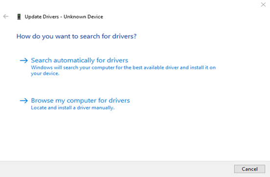
After driver installation, run PhoenixSuit.exe. The bottom-left should show “Device connected successfully”.
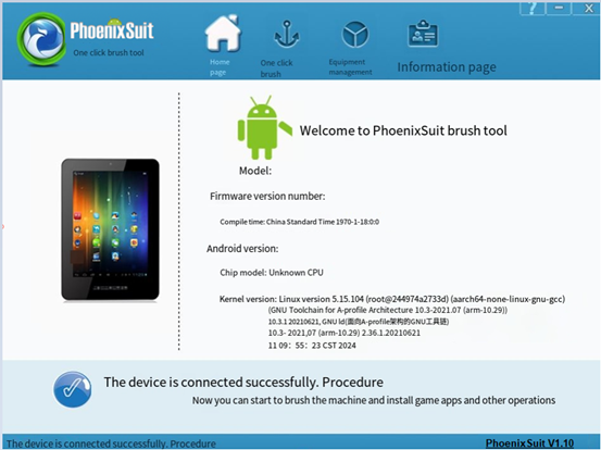
6.2.2 OTG Flashing Methods
Complete OTG Flashing.
This programming method will program the entire img image.
In the following interface, click “One-click Flash” and then click “Browse” to select the firmware image file.
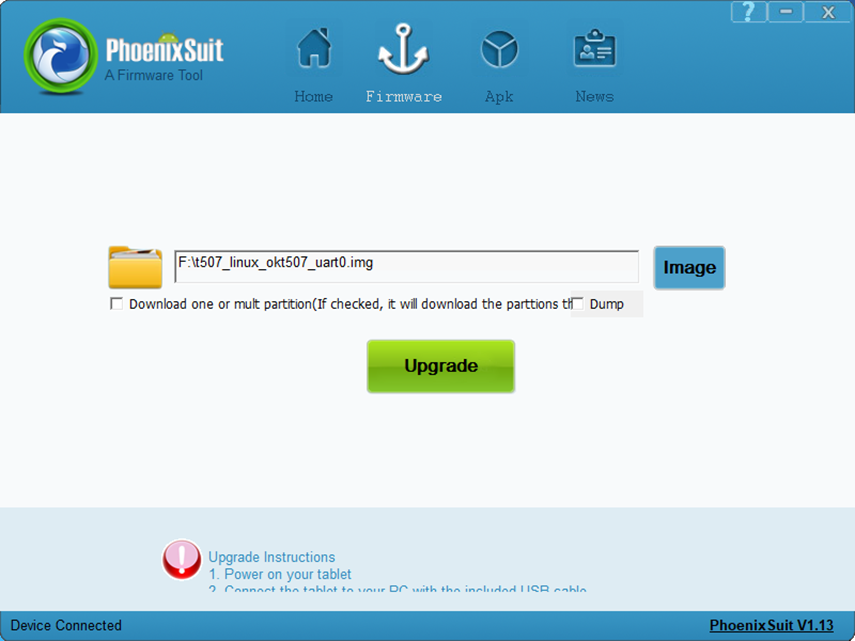
Connect the development board to the host computer using a Type-A to Type-C cable. Do not power on the board initially; press the USBLOAD button, then power on the board, and finally release the USBLOAD button.
Note: You must press the USBLOAD button whilst the power is off.
In the following interface, click “Yes” to enter the formatting upgrade mode:
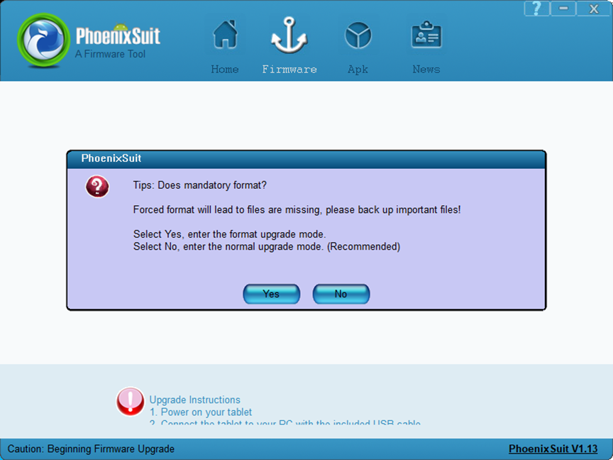
Wait for the programming to complete. Then, the following interface will pop up:
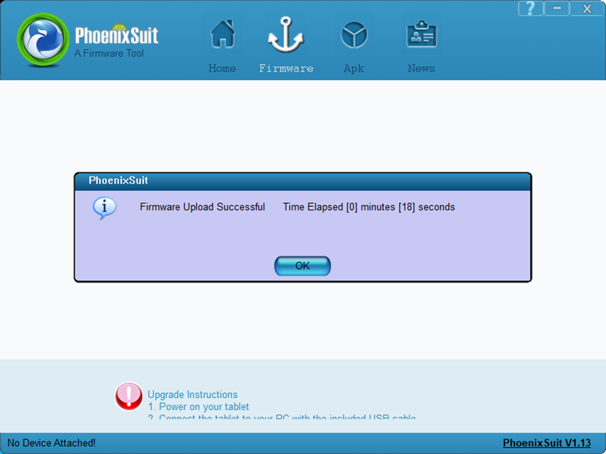
After the flashing, the board will automatically power on
Partial Image Updates
OTG uboot separate programming test
In the following interface, check the checkbox “Single or multi-partition download (select this option, the flashing tool will download the partitions you have selected)”, then check the “BOOT-RESOURCE” and “ENV” checkboxes.
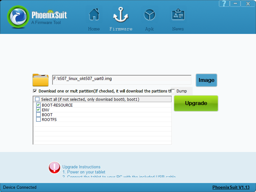
Connect the development board to the host computer using a Type-A to Type-C cable. Do not power on the board initially; press the USBLOAD button, then power on the board, and finally release the USBLOAD button. Wait for the programming to complete. Then, the following interface will pop up:
Note: You must press the USBLOAD button whilst the power is off.
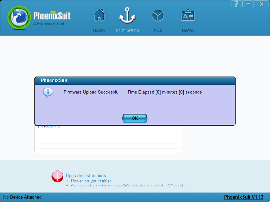
OTG Flashing Kernel Image and Device Tree DTB File
In the following interface, check the checkbox “Single or multi-partition download (select this option, the flashing tool will download the partitions you have selected)”, then check “BOOT-RESOURCE” and “BOOT”.
The kernel image is placed in the “BOOT” partition.
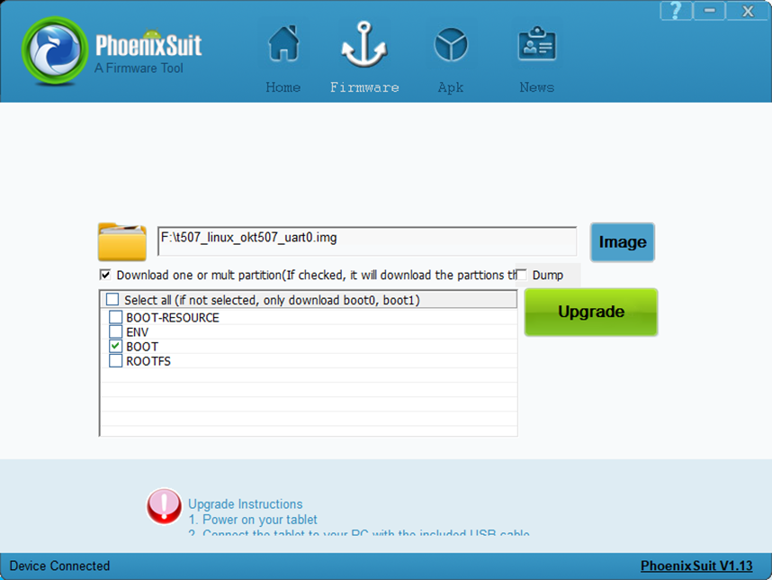
Connect the development board to the host computer using a Type-A to Type-C cable. Do not power on the board initially; press the USBLOAD button, then power on the board, and finally release the USBLOAD button. Wait for the programming to complete. Then, the following interface will pop up:
Note: You must press the USBLOAD button whilst the power is off.
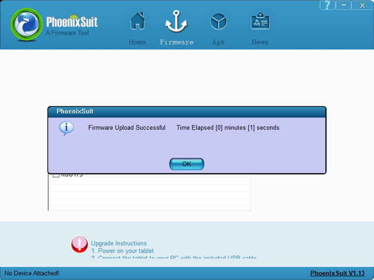
OTG System Flashing
In the following interface, check the checkbox “Single or multi-partition download (select this option, the flashing tool will download the partitions you have selected)”, then check “ROOTFS”.
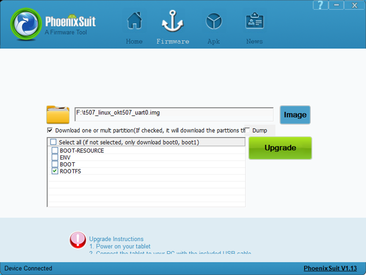
Connect the development board to the host computer using a Type-A to Type-C cable. Do not power on the board initially; press the USBLOAD button, then power on the board, and finally release the USBLOAD button. Wait for the programming to complete. Then, the following interface will pop up:
Note: You must press the USBLOAD button whilst the power is off.
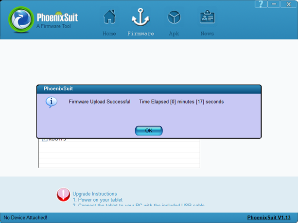
6.2.3 Common OTG Flashing Issues
Driver Installation Failure
After following the manual to install the USB driver, some users still see an “Unknown device” in Device Manager. When expanding the “Unknown device” details, a message appears indicating that the third-party INF does not contain digital signature information, as shown in the figure below:
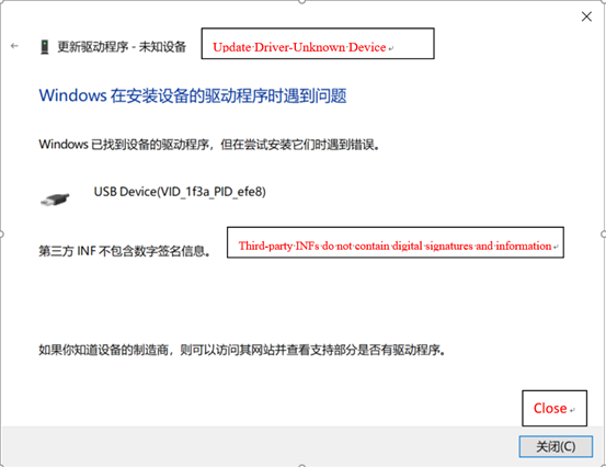
This issue occurs because some Windows systems, in order to prevent third-party programs from affecting system stability, block unsigned drivers from passing verification, causing the driver installation to fail. First disable the driver signature enforcement setting on the computer, and then proceed with the driver installation according to the manual.
Solution for “Third-party INF does not contain digital signature information” issue.
First press and hold Shift + Restart;
When starting up, select Troubleshoot → Advanced Options → Startup Settings;
On the Startup Settings screen, click Restart in the bottom right corner. After restarting and entering Startup Settings, press the number key 7 or function key F7 to disable driver signature enforcemen.
Incorrect use of the USBLOAD button
When programming, do not power the board initially; press the USBLOAD button, then power the board on, and finally release the USBLOAD button.
Device name appears but the board still cannot be recognized
This may be because there are many unknown devices in Device Manager, and selecting the wrong one could cause the driver to be installed to another device. First right-click the device item mentioned above, select “Uninstall device”, and check “Delete the driver software for this device”.
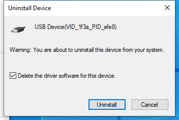
After uninstalling, disconnect other USB devices connected to the host, put the development board into flashing mode and connect it to the host, then repeat the above steps for installation.
6.3 TF Card Flashing
6.3.1 Creating a TF Flashing Card
Tool path: 3-Tools\PhoenixCard_V4.1.9.zip
Insert an 8GB/16GB/32GB TF card into the PC’s USB interface via a card reader.
Copy the flashing tool PhoenixCard_V4.1.9.zip to any Windows directory, and double-click PhoenixCard.exe in the PhoenixCard_V4.1.9 folder.
The following interface will appear:
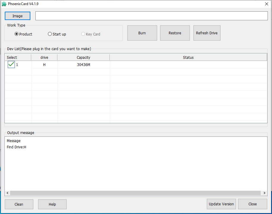
Note: If the TF card has multiple partitions, click “Restore Card” first, then click “Burn Card”; otherwise, the burning process may fail.
Click “Firmware” to browse and select the OK536 firmware image, select “Mass Production Card”, and click “Burn Card”.
Wait for the burning process to complete, as shown in the following interface:

6.3.2 TF Card Flashing Method
Insert the TF card, power on the board, and the system will automatically enter the flashing process.
Serial port prompt upon completion:
chunk 3864(3867)
chunk 3865(3867)
chunk 3866(3867)
successed in writting part rootfs
origin_verify value = 9a3e3a97, active_verify value = 9a3e3a97
successed in verify part rootfs
successed in download part rootfs
successed in downloading part
[67.156]uboot size = 0x16c000
[67.159]storage type = 2
sunxi_sprite_deal_uboot ok
successed in downloading uboot
[67.242][mmc]: write mmc 2 info ok
[67.245]storage type = 2
successed in downloading boot0
CARD OK
sprite success
sprite_next_work=3
next work 3
SUNXI_UPDATE_NEXT_ACTION_SHUTDOWN
Remove the TF card and power on the board to start the system;
Restoring the TF Card.