OK3562 5.10.96 Adaptation for MCP2518 CANFD
OK3562 supports SPI-to-CANFD conversion. There is already a driver for SPI-to-CANFD in the kernel. Below is the process and testing method for adapting the MCP2518.
Note: OK3562 features a set of SPI pins labeled [P8], which can support SPI-to-CANFD conversion.
1. Driver Adaptation
There is already a MCP2518 driver file in the kernel, which needs to be configured into the kernel via the configuration file;
Open the graphical configuration interface in the kernel using
make menuconfig ARCH=arm64.
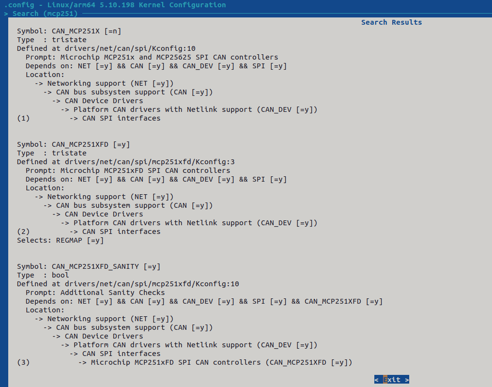
The CAN _ MCP251XFD in the figure above is the driver for the MCP2518 module.

/mcp251search MCP2518 driver;Select “2” to compile it into the kernel as
*;Select
saveto save the configuration to the defconfig file, file path:/home/forlinx/3562/OK3562-linux-source/kernel/arch/arm64/configs/OK3562_Linux_defconfig
2. Device Tree Adaptation
The OK3562 has a set of SPI pins exposed.
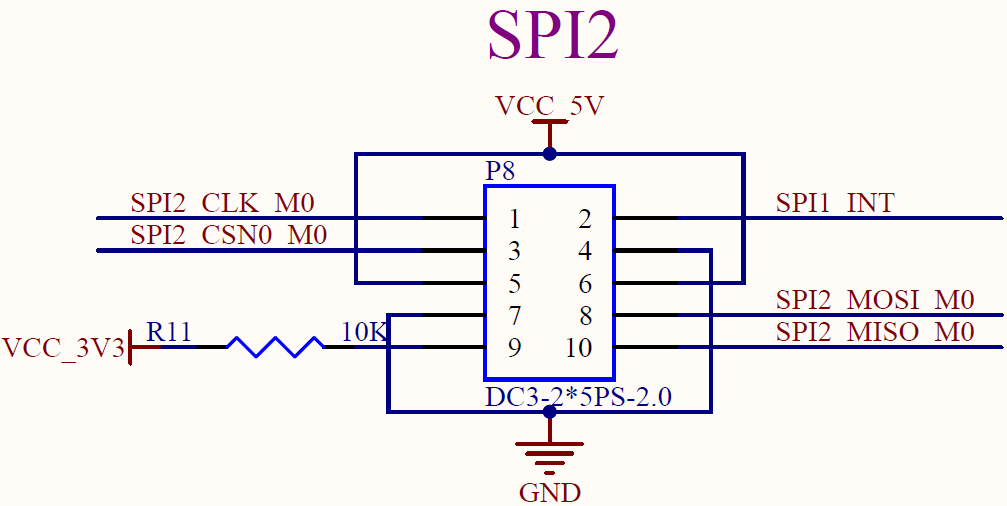
After the driver is configured, the device tree file to be configured is:
OK3562-C-common.dtsi;The specific configuration information is as follows:
diff --git a/arch/arm64/boot/dts/rockchip/OK3562-C-common.dtsi b/arch/arm64/boot/dts/rockchip/OK3562-C-common.dtsi
index 158f03d70..671a491bf 100644
--- a/arch/arm64/boot/dts/rockchip/OK3562-C-common.dtsi
+++ b/arch/arm64/boot/dts/rockchip/OK3562-C-common.dtsi
@@ -19,6 +19,12 @@
        model = "Forlinx OK3562 Board";
        compatible = "forlinx,ok3562", "rockchip,rk3562";

+       mcp2518_clk: mcp2518-clk {
+            compatible = "fixed-clock";
+            #clock-cells = <0>;
+            clock-frequency = <40000000>;
+        };
+
        forlinx-control {
                status = "disabled";
                disp_type = "mipi";     //mipi or lvds
@@ -662,6 +668,13 @@
 };

 &pinctrl {
+
+       mcp2518 {
+               mcp2518_irq_pins:mcp2518_irq_pins {
+                       rockchip,pins = <4 RK_PB0 RK_FUNC_GPIO &pcfg_pull_none>;
+               };
+       };
+
        touch {
                gt928_lvds_gpio:gt928-lvds-gpio {
                        rockchip,pins = <3 RK_PB0 RK_FUNC_GPIO &pcfg_pull_none>,
@@ -980,13 +993,24 @@


 &spi2 {
+       pinctrl-names = "default";
+       pinctrl-0 = <&spi2m0_csn0 &spi2m0_csn1 &spi2m0_pins>;
        status = "okay";
-       spi_dev0: spi@0 {
+/*     spi_dev0: spi@0 {
                compatible = "rohm,dh2228fv";
                pl022,com-mode = <1>;
                spi-max-frequency = <10000000>;
                reg = <0>;
                status = "okay";
+       };*/
+       spi@0{
+               compatible = "microchip,mcp2518fd";
+               reg = <0>;
+               clocks = <&mcp2518_clk>;
+               pinctrl-names = "default";
+               pinctrl-0 = <&mcp2518_irq_pins>;
+               spi-max-frequency = <20000000>;
+               interrupts-extended= <&gpio4 RK_PB0 IRQ_TYPE_LEVEL_LOW>;
        };
 };
mcp2518 _ clkis the clock frequency node to match the actual crystal frequency of the module;The
INTpin on the module is the interrupt pin of the module, and a controllable GPIO pin needs to be connected as the interrupt pin during adaptation;Add the device tree information of the matching MCP2518 driver under the
spi2node. Thecompatibleinformation cannot be wrong. This is an important attribute of the matching driver.
3. Compilation and Flashing
Once the driver and device tree configurations are completed as described above, you can proceed to compile the kernel and flash it onto the development board for testing
Compile the kernel separately in the source directory;
forlinx@ubuntu:~/3562/OK3562-linux-source$ ./build.sh kernel
An image file named
boot.imgwill be generated in thekerneldirectory within the source code directory;To flash the image file onto the development board, you will need the
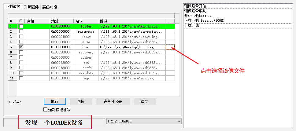
RKDevTool; this tool can be found in the OK3562 documentation package;○ Open the flashing tool; ○ Connect the PC to the Type-C0 port on the bottom of the development board using a Type-C cable; ○ Hold down the Recovery button on the development board and do not release it; then restart the development board; ○ Note that the tool will detect whether the development board has entered flashing mode .
Select the pre-compiled
boot.imgimage file, tick the box next to the “boot”option, click “Execute” to flash the image; once flashing is complete, the development board will restart automatically.
4. Function Test
Search for CAN nodes on the development board using the ifconfig -a command.

You can see the generated “can0” node.
For functional testing, the CAN0 ports on the OK3562 and OK3568 development boards are used to test data transmission between them.
a. OK3562 receives data
Set the baud rate for CAN0.
ip link set can0 type can bitrate 500000
Open the CAN0 device and configure CAN0 to act as a server to receive data.
ifconfig can0 up 	//Open the CAN0 device
candump can0&		//Set the can0 device as the server

Configure CAN0 on the OK3568 as a client to send messages to CAN0 on the OK3562.
ifconfig can0 down
ip link set can0 up type can bitrate 500000
ifconfig can0 up
cansend can0 123#1122334aabbccd		//Send a message

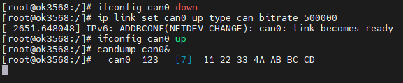
OK3562 will receive a message from OK3568 .

P.S.: The error shown in the image above is due to an issue with the MCP2518 driver; this will not affect communication during testing.
b. OK3562 sends data
Configuration of the baud rate and other settings is carried out as described above; when configuring functions, use the cansend command to send data.

Configure OK3568 as a server to receive data, following the method used for OK3562.
ifconfig can0 down
ip link set can0 up type can bitrate 500000
ifconfig can0 up
candump can0&
The above is the whole process of OK3562 adapting and testing MCP2518 module. If you have any questions, please contact Forlinx Technical Support.