AI Algorithm User Manual V1.0
Document classification: □ Top secret □ Secret □ Internal information ■ Open
Copyright
The copyright of this manual belongs to Baoding Folinx Embedded Technology Co., Ltd. Without the written permission of our company, no organizations or individuals have the right to copy, distribute, or reproduce any part of this manual in any form, and violators will be held legally responsible.
Forlinx adheres to copyrights of all graphics and texts used in all publications in original or license-free forms.
The drivers and utilities used for the components are subject to the copyrights of the respective manufacturers. The license conditions of the respective manufacturer are to be adhered to. Related license expenses for the operating system and applications should be calculated/declared separately by the related party or its representatives.
1. Overview
The AI application for the FCU runs on multiple platforms. Once installed, it can be accessed and configured through a web browser.
1.1 Starting the Web Service
The following line is present at the end of /etc/rc.local:
/web/shell/up.sh
up.sh starts the Boa service and runs the start.sh script. Boa is the backend web service and listens on port 80 by default. To change the port, edit /web/boa/boa.conf and modify the number in the Port 80 directive.
Two lines are configured in /etc/profile:
export LD_LIBRARY_PATH=/web/lib:/web/lib/opencv2
export PATH=$PATH:/web/shell
Do not change this configuration. The PATH entry lets you call the four scripts in /web/shell — up.sh, start.sh, stop.sh, and restart.sh — directly from the command line.
Script |
Function |
|---|---|
|
Starts the web service |
|
Stops the web service |
|
Restarts the web service |
|
Shows the web service status |
2. Using the AI Web Interface
2.1 Signing In
Before signing in, assign the device an accessible IP address. Once the address is reachable (for example, it responds to ping), open a browser and enter http://<IP> to load the web interface.
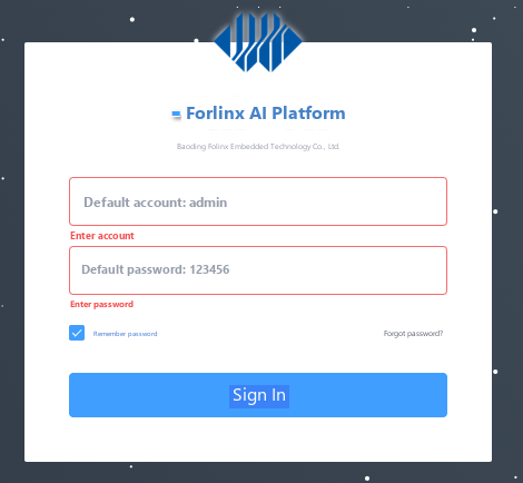
The account and password fields on the sign-in page show hints for the default credentials. Enter the user name and password as prompted, then click Sign In.
Tip: select Remember Password to have the credentials filled in automatically next time.
2.2 Session Persistence
Once the page stops polling the backend, the server keeps the session valid for 24 hours. The web interface also refreshes the session every hour, so as long as the page stays open, the session will not expire. If the browser tab is sent to the background, however, it may stop running the JavaScript — and if that lasts more than 24 hours, the session will expire. In short: keep the page open and visible, and the session stays alive.
2.3 Dashboard
The dashboard shows the monitoring wall: camera online status, live alarms, camera previews, and various statistics.
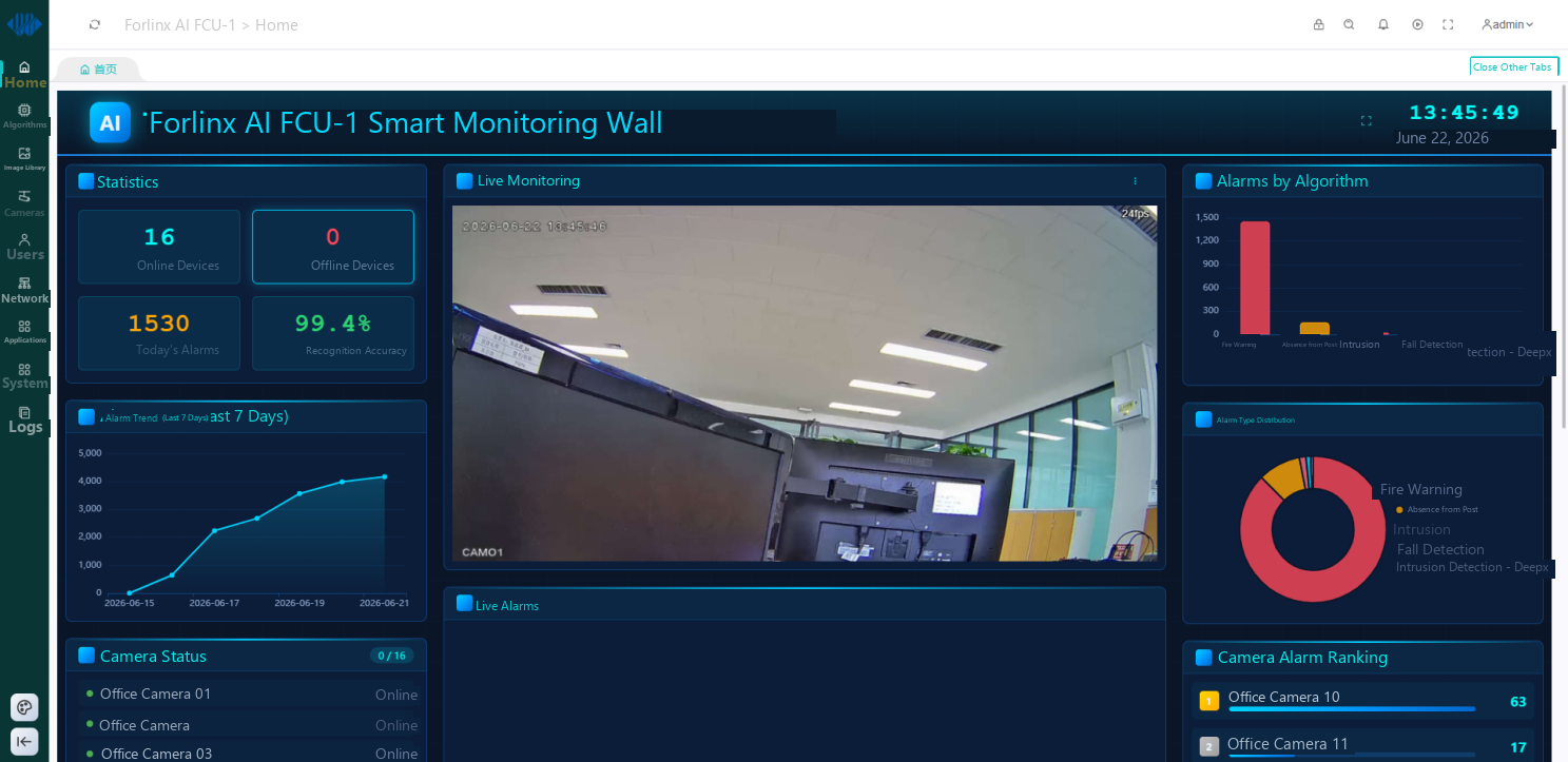
The monitoring wall supports full-screen display. Click the full-screen button to the left of the clock in the top-right corner:

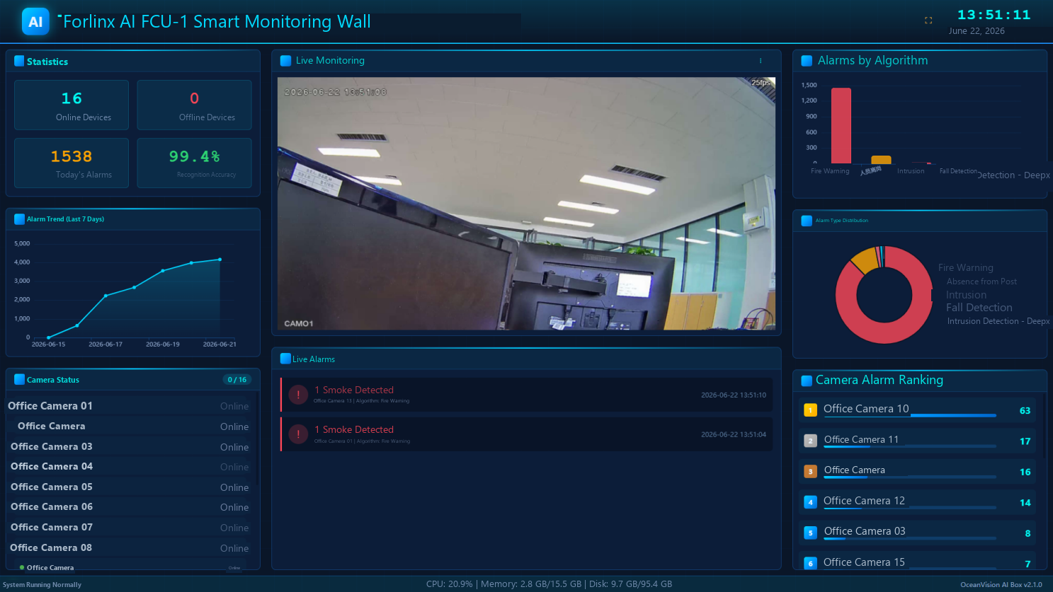
Press Esc or click the icon again to exit full screen.
Live monitoring tiles can also be expanded by double-clicking the video (this shows the live feed only).
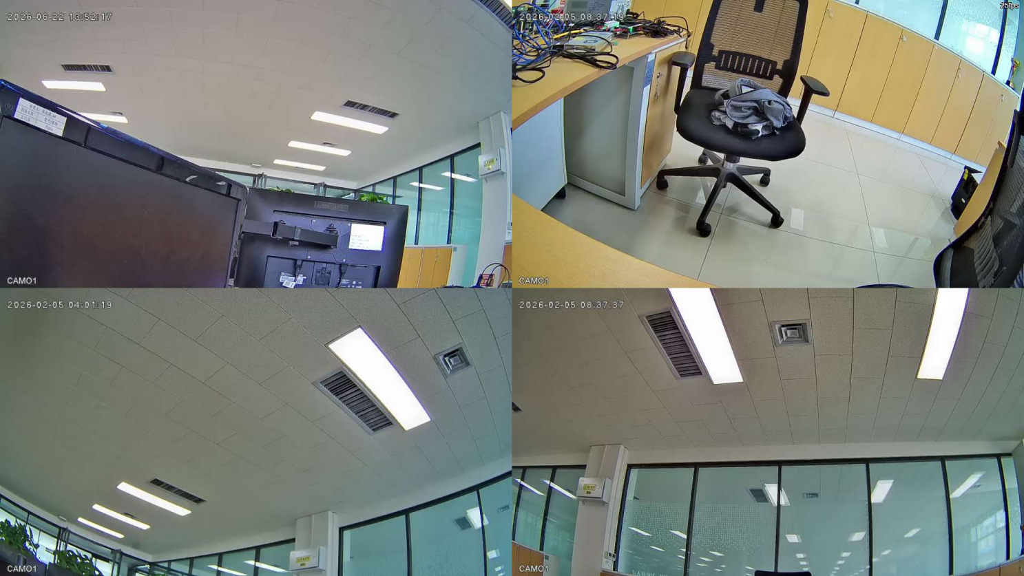
In the top-right corner of the live view there is a vertical three-dot menu (also available in full-screen mode). Clicking it opens a floating camera list where you can select multiple cameras for preview.
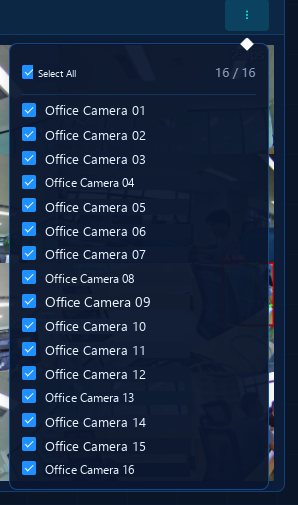
The preview is mainly used to show inference results. The label in the top-left corner of each bounding box indicates the inference result.
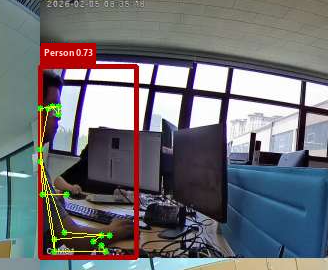
The screenshot above shows the fall-detection algorithm enabled: when the inference result includes both person detection and pose estimation, the system draws bounding boxes and pose keypoint connections.
2.4 Algorithms
2.4.1 Algorithm Categories
Algorithm categories group algorithms so that, when assigning algorithms to a camera, you can pick a category first and then a specific algorithm. The category page supports adding, editing, and deleting categories.
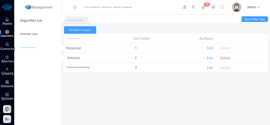
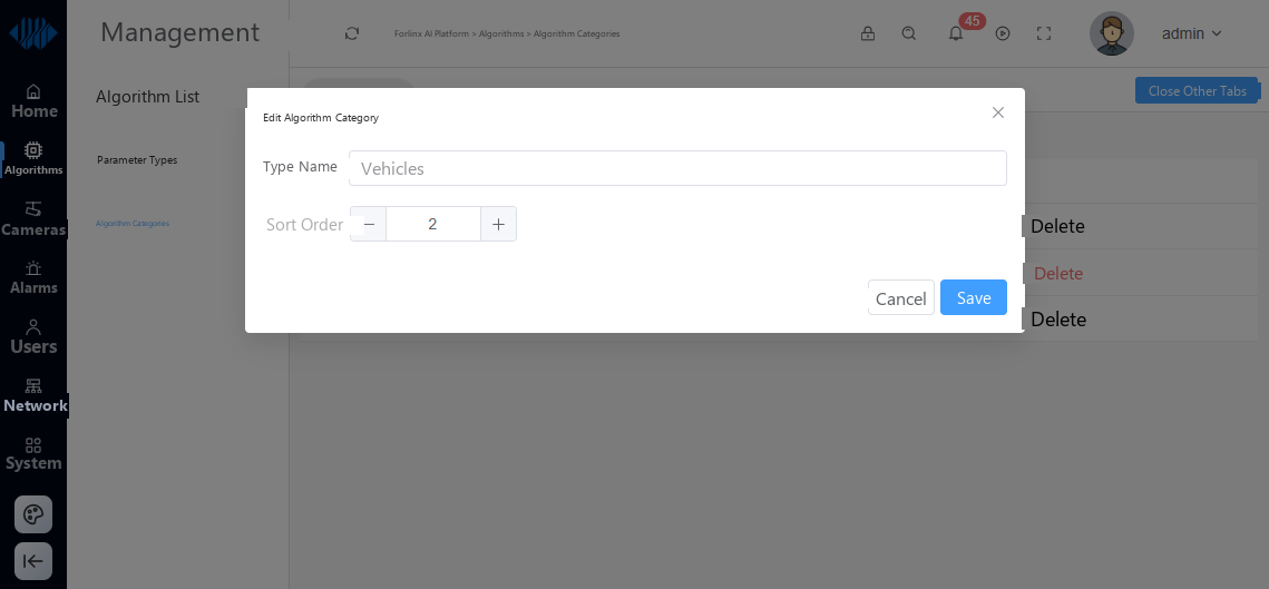
Categories are sorted by their numeric value, in ascending order.
2.4.2 Parameter Types
Some algorithms share the same parameters. Fire detection, hard-hat detection, and smoking detection, for example, are all object-detection algorithms with identical parameters, so they are assigned the same parameter type when deployed. This page is normally maintained by the algorithm developer, since only the developer knows which parameters a given algorithm uses.
2.4.3 Algorithm List
The algorithm list maintains the algorithms available on the system. Adding and editing algorithms is a developer task, because only the developer knows which algorithm file (libxxx.so) and which model file (xxx.rknn) a given algorithm uses. Once an algorithm is set up, the developer exports it as a {algorithm-name}.algo file; users then import that file.
To add an algorithm:
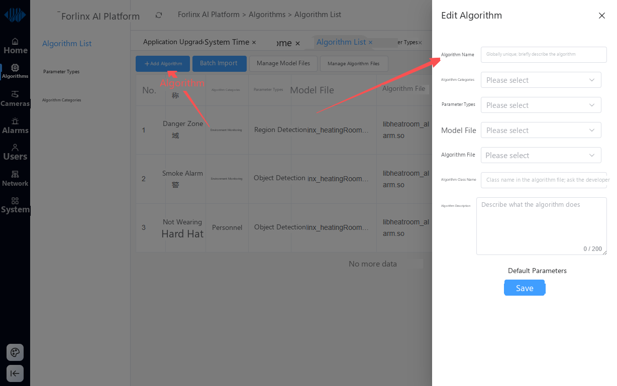
Algorithm Name — a short summary of what the algorithm does, so users can identify it.
Algorithm Category — used only to group algorithms when assigning them to cameras; pick the category the algorithm belongs to.
Parameter Type — closely tied to the algorithm source code. Once a parameter type is selected, the code can access the parameters configured for each camera in the camera list.
Model File — the inference file used by the algorithm. It becomes selectable here only after you upload it with the Manage Model Files button on the algorithm list page.
Algorithm File — the shared library into which the algorithm is compiled. It becomes selectable here only after you upload it with the Manage Algorithm Files button.
Algorithm Class Name — the C++ class name of the algorithm.
Algorithm Description — describes what the algorithm does. It has no effect at runtime.
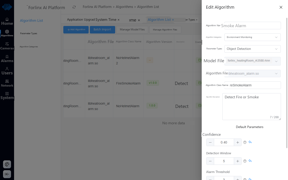
Default Parameters — populated automatically from the selected parameter type. When a new camera is created, these defaults are used to prefill its configuration.
The configuration for the smoke alarm algorithm, for example, looks like this:
To develop your own algorithm, contact us for sample code.
After an algorithm is added, use the Enable / Disable buttons in the Actions column to turn it on or off. Note that enabling or disabling only controls whether the algorithm can be selected in the camera list — algorithms already assigned to a camera keep running even if they are disabled.
The model file management page looks like this:
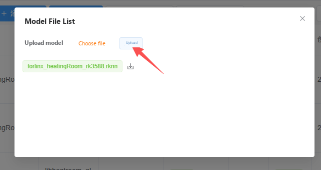
Click Choose File, select an xxx.rknn file, then click Upload. If the file name matches an existing model, a dialog asks whether to continue:
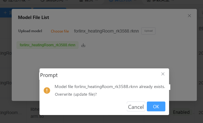
Click Confirm to update the file. If no file of that name exists, the upload succeeds directly.
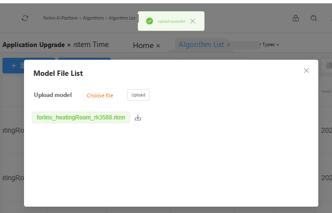
Once the algorithm is ready, click Export to export it as an xxx.algo file. Send that file to the user, who imports it and can then assign the algorithm to cameras.
2.5 Image Library
2.5.1 Face Database
The face database page maintains the data used for face recognition. Photos should resemble an ID portrait: the face should occupy most of the frame.
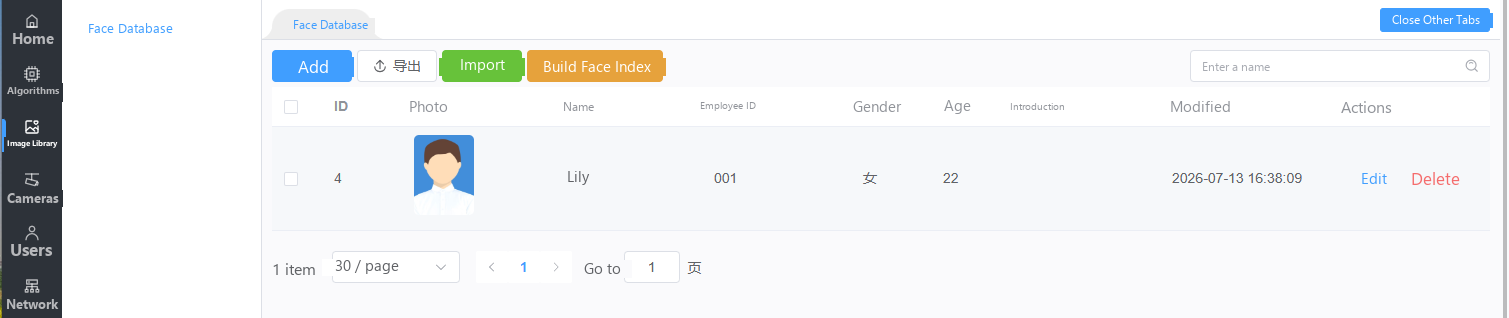
Add — click Add, enter the person’s name, gender, and other details, upload a face image (JPG or PNG), and click Save.
Edit — modify the details or the image of an existing record.
Delete — remove a face record.
Importing a Face Database:
Prepare the face images, resize them to a width of 600 px, and convert them all to .jpg (PNG is not supported). With at least one face record already added on the page, click Export and unzip the downloaded archive. Edit human_face.csv inside it (in Excel or WPS): fill the id column with values from 1 to N (Excel’s drag-to-fill handles the increment), and prepare a {id}.jpg image for each id — for example, record 1 needs 1.jpg. Then select all the files, compress them into a xxxx.zip archive, click Import, choose that archive, and click Open. If something is wrong, the system reports the specific error; correct the data or add the missing images accordingly.
2.6 Cameras
2.6.1 Camera List
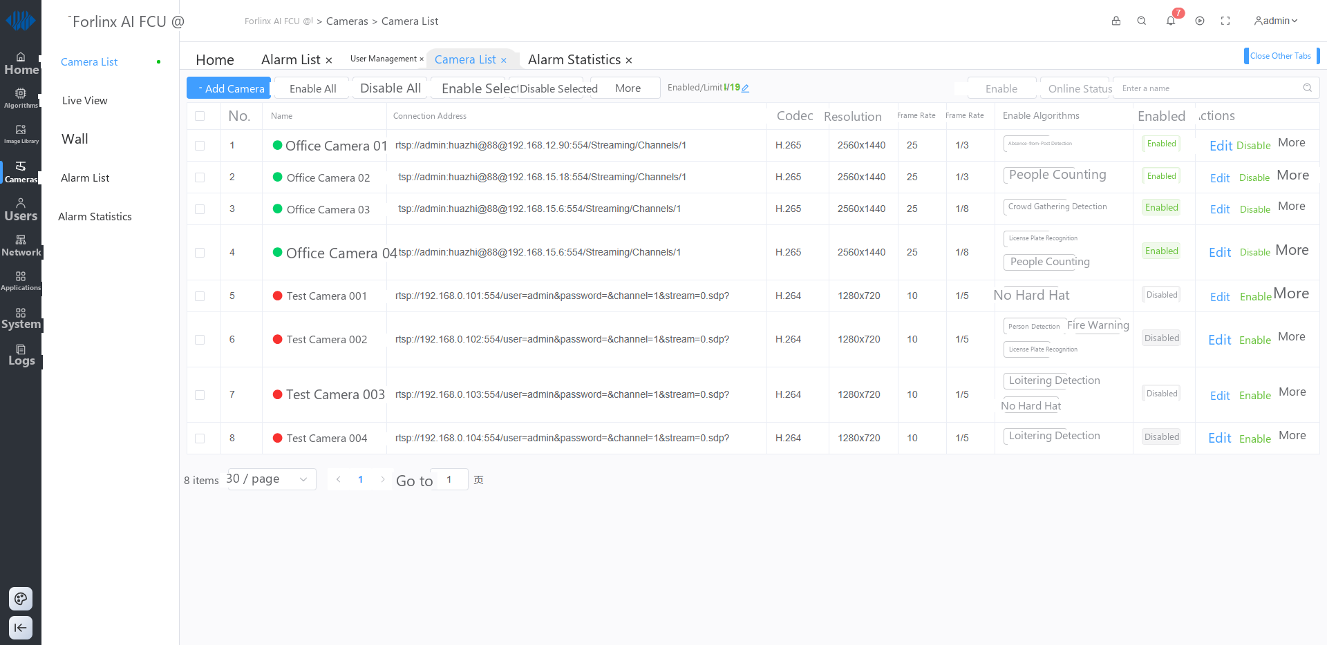
The camera list shows every configured camera.
To add a camera:
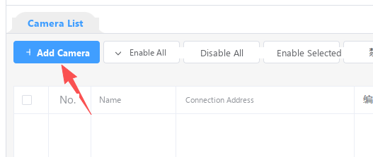
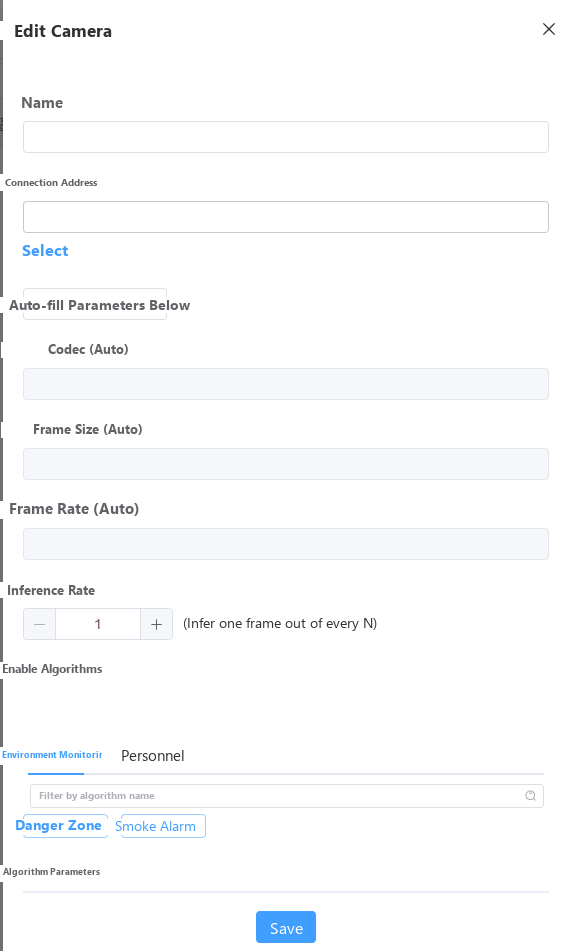
As shown above, the name can reflect the camera’s location or purpose.
The connection address must match the RTSP address provided by the camera vendor. For a Hikvision camera, for example, obtain the camera’s IP address, port, user name, and password, then substitute them into this format:
rtsp://username:password@IP:port/Streaming/Channels/1
For a camera with IP 192.168.12.68, port 554, user name admin, and password 12345678, the RTSP stream address is:
rtsp://admin:12345678@192.168.12.68:554/Streaming/Channels/1
After entering the address, click Capture (test the camera) to take a snapshot and verify the camera works, then click Auto-Fill Parameters Below:
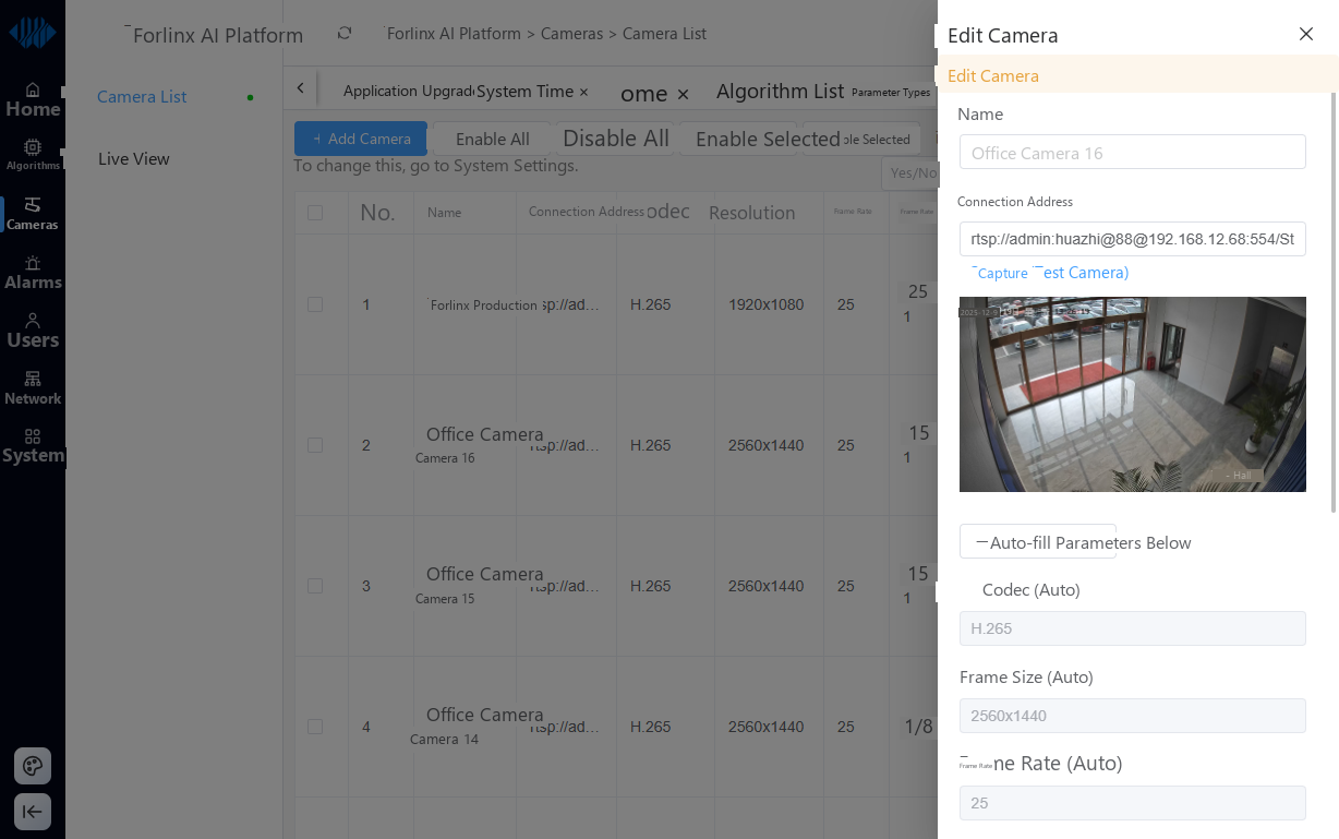
The codec, frame size, and frame rate are detected when you click that button.
Inference Rate — set according to the camera’s frame rate. At 25 fps the camera delivers 25 frames per second; an inference rate of 5 means one frame in every five is inferred, i.e. 5 frames per second are actually processed. Choose a rate that meets your business needs while using GPU inference and RGA image-processing resources sensibly.
Enabling Algorithms — click a category tab to switch between the algorithms in each category. If there are too many, type a name to filter. Click an algorithm name to add it to the enabled list:
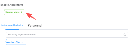
Note: once an algorithm is added, it disappears from the category list below and appears in the enabled list above.
After an algorithm is added, its parameters appear below. Click the algorithm name under Algorithm Parameters to expand the details.
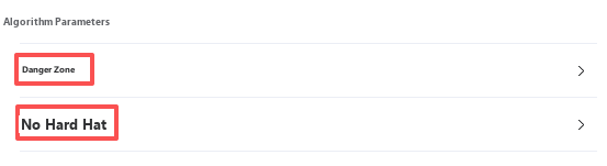
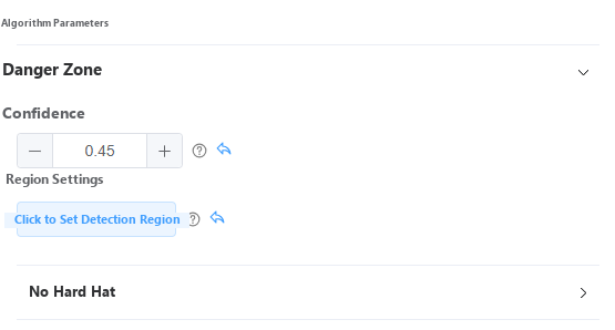
The specific parameters depend on the algorithm; see the algorithm reference chapter.
When you are done, click Save to add the camera. A new camera is disabled by default. Click the status text, or the Disable / Enable buttons in the Actions column, to toggle its state.
Tip for Adding Many Cameras at Once:
Add one camera and name it “Camera 01”;
Use Clone: the dialog increments the name to “Camera 02” and the last octet of the RTSP IP address by one, so you can simply click Save. Repeat until you have the required number of cameras;
Click More, then Export Camera Configuration to download an Excel file. Edit each camera’s name and address in the file (only columns other than
idmay be changed — adding or deleting rows is not allowed), then click Import Camera Configuration and select the edited file. All cameras are now configured.
If every camera uses the same algorithm and parameters, no further work is needed. Otherwise, adjust the algorithms and parameters for each camera individually.
The buttons in the camera Actions column:
Edit — modify an existing camera;
Disable / Enable — turn the camera off or on;
More — additional functions:
Recorded Video List — click More next to a camera, then Recorded Video List. In the dialog, click Request Video Recording, enter a duration in minutes (1–10), and confirm. After that time has elapsed, reopen the list to see the recording, which you can play, download, or delete:
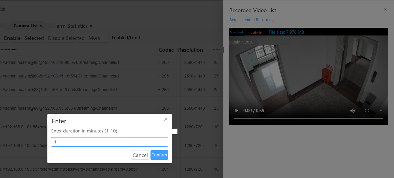
Note: inference pauses while recording, so the live view shows no bounding boxes.
Sync Device Algorithms — copy the current camera’s algorithms and parameters to other cameras, so they use the same configuration. A dialog lists all cameras for selection.
Clone — create a new camera based on this one, with the same settings.
Detect — check the camera’s codec, resolution, and frame rate (the same as Auto-Fill Parameters Below in the edit dialog).
Alarms — jump to the alarm page, filtered to this camera’s alarms.
Delete — prompts for confirmation, then deletes the camera.
More (page-level) — the dialog offers Export Camera Configuration and Import Camera Configuration. Export, edit each camera’s address and name, then import again. This is the practical way to change many camera addresses at once.
2.6.2 Live View
Click Cameras → Live View in the left menu. The page opens with the first enabled camera displayed.
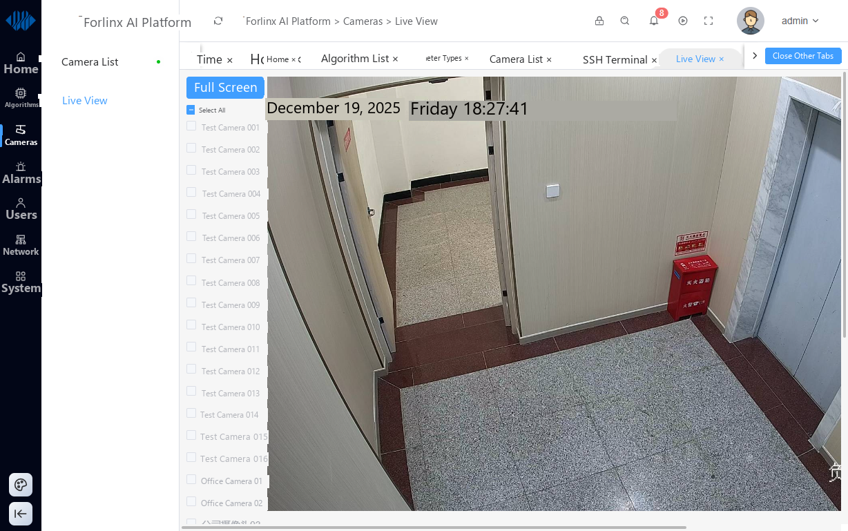
This page is used to monitor capture status and algorithm hits. When an alarm algorithm matches a target, the bounding-box information is pushed to the live view.
When several streams are selected, the backend tiles them automatically. 4-up, 9-up, and 16-up layouts are supported.
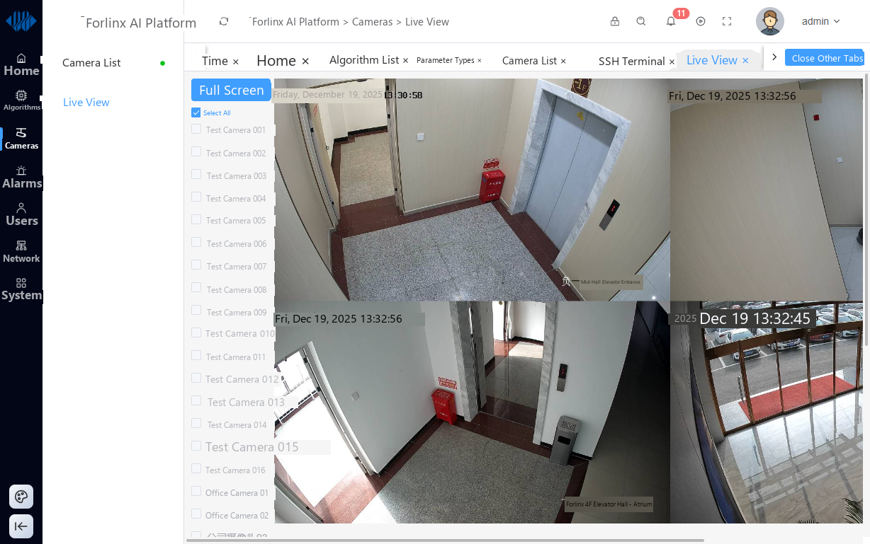
Note: a hit does not necessarily raise an alarm — alarms depend on the algorithm’s threshold parameters. Hard-hat detection, for example, may require several hits (configurable) before one alarm is raised, and only one alarm is raised within a given interval.
2.6.3 Live Alarms
Click the play button to the left of the avatar to toggle live alarms:


Once the button switches to the pause icon, any live alarm pops up a message on the left side of the page.
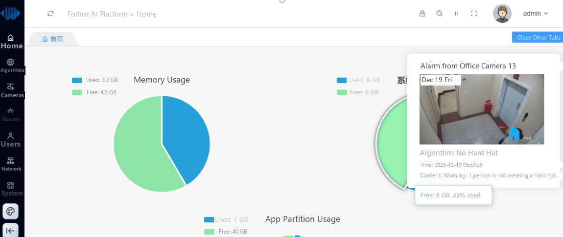
If you click the pause button, it reverts to the play icon and live alarms are only indicated by a numeric badge on the bell icon:

2.6.4 Alarm List
Click the bell icon in the top-right corner, or choose Alarms → Alarm List in the left menu, to open the alarm list. This page shows the historical alarms from all cameras (snapshots are masked to protect privacy).
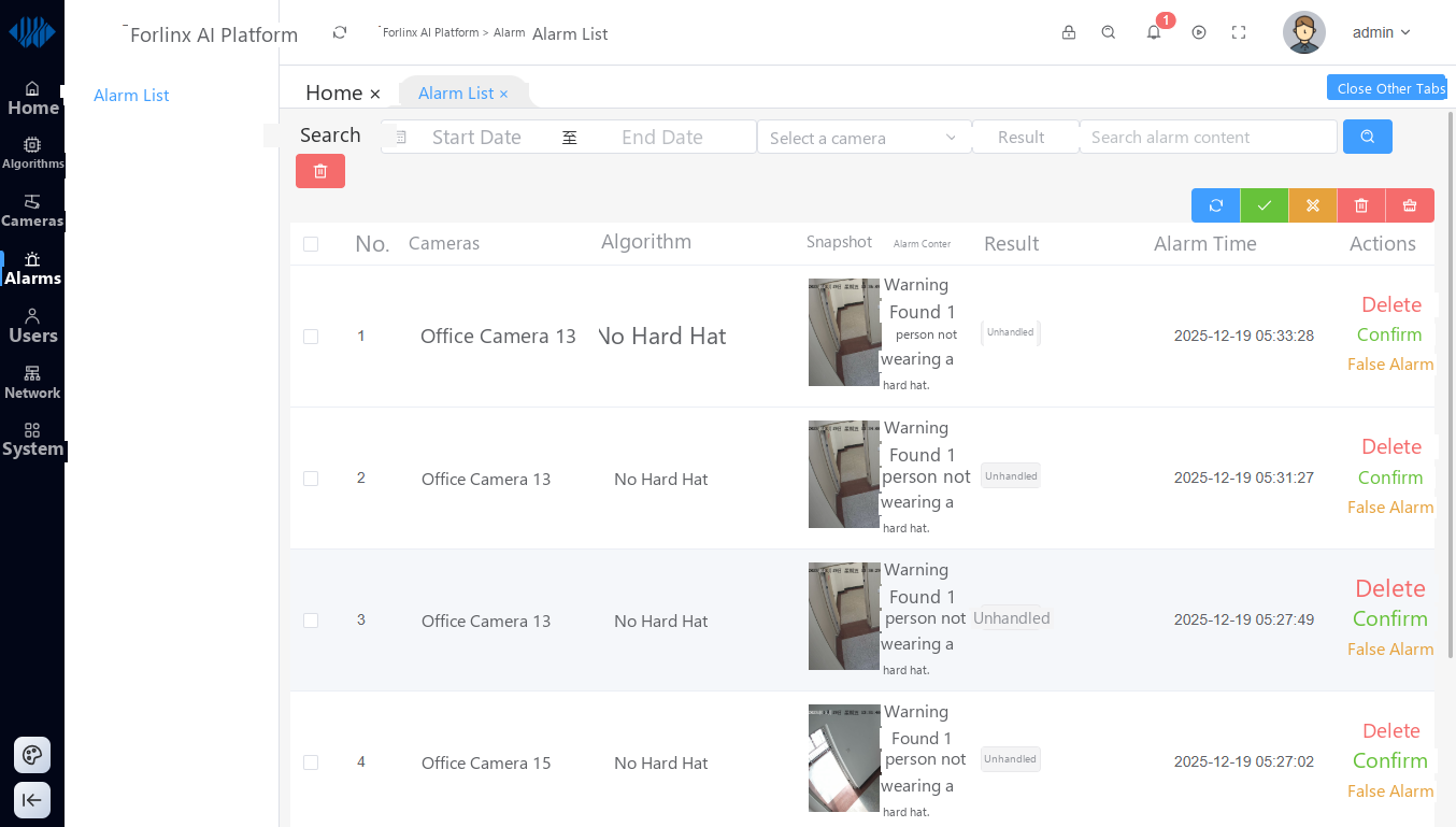
Alarm records can be acknowledged, marked as false alarms, or deleted.
Select the checkboxes on the left and use the buttons in the top-right corner to act on several records at once.
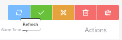
Note: the last button clears all alarm records. It is intended for use after deployment testing and before going live — use it with care.

2.7 Users
2.7.1 User Management
The user management page supports adding, editing, and deleting users.
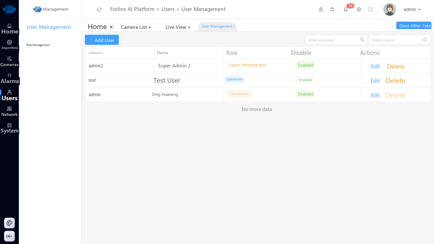
User name, password, display name, and role can all be modified.
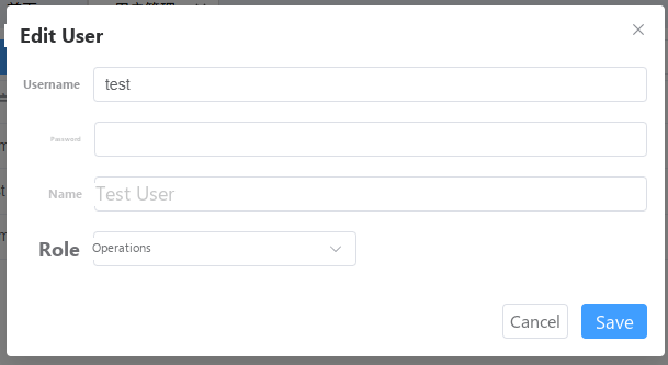
The built-in account is listed at the bottom. It cannot be deleted and its role cannot be changed, which prevents an accidental lockout with no account left to manage the web interface.
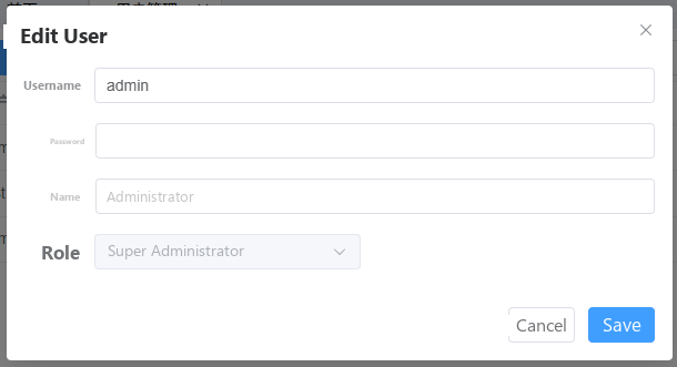
Note: the role drop-down is populated from the role management page. If you do not need fine-grained roles, simply use the built-in admin account.
2.7.2 Role Management
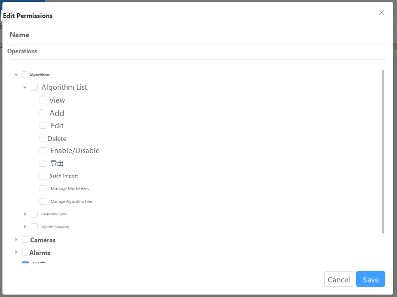
If you need to separate permissions, open the role page, add roles, and configure page and button permissions for each role:
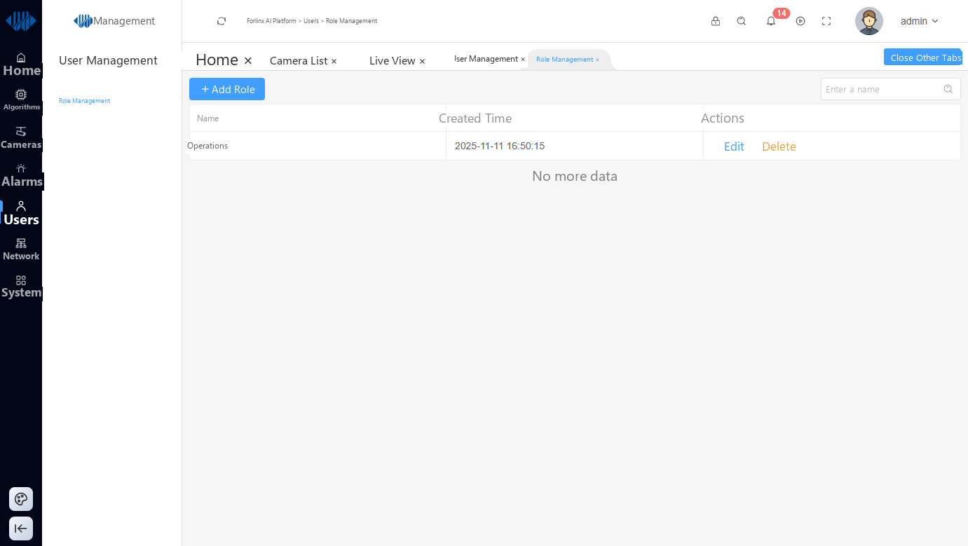
The first and second levels correspond to the first- and second-level menus on the left; the third level corresponds to the action buttons inside a page. View grants access to the page — without it, visiting the page redirects to a “no permission” page.
Note: the super administrator role is not listed. That account is not subject to permission control and has all permissions by default.
2.8 Network
2.8.1 Wired Network
The wired network page shows the NIC’s MAC address and IP configuration.
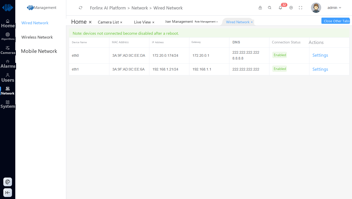
Click Settings to configure the network:
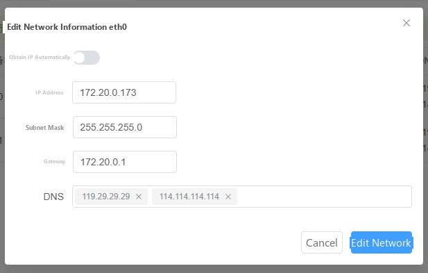
There is no limit on the number of DNS servers, but one or two is normally enough.
2.8.2 Wireless Network
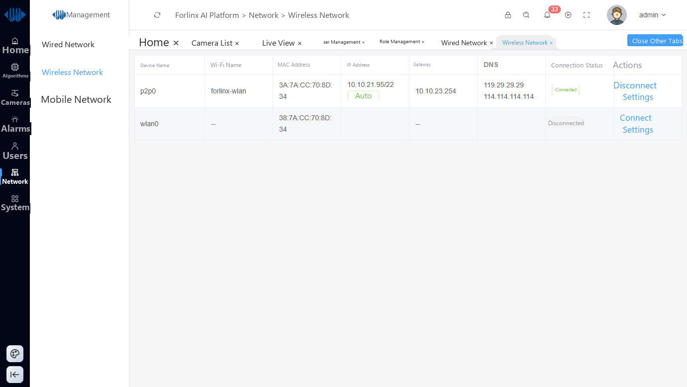
Click Settings to configure the Wi-Fi connection’s IP address.
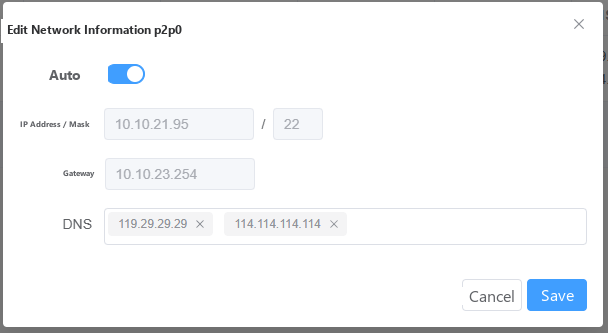
Click Connect in the list to open the Wi-Fi list, choose a network, click Connect, enter the password, and confirm.
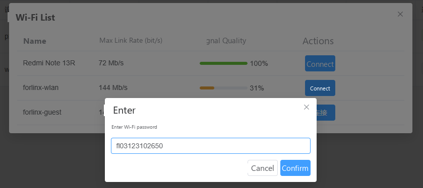
Once connected, the status shows as connected.
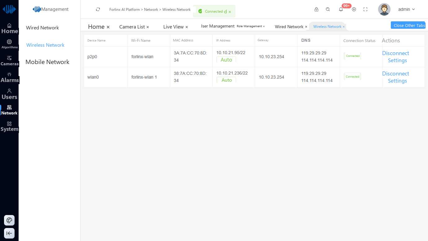
Note: after a successful connection, the device reconnects to that Wi-Fi network automatically after a restart.
2.8.3 Mobile Network
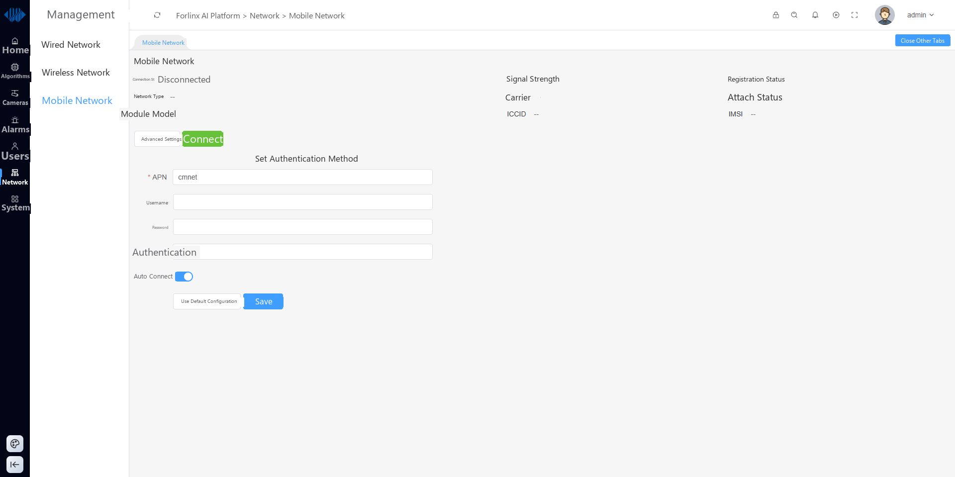
For a standard IoT SIM card, no user name or authentication method is needed: leave the APN at its default value cmnet and the authentication method at 1. Set the connection to automatic and save, so the background process keeps the mobile connection alive.
2.9 Applications
2.9.1 Application Monitoring
The application monitoring page shows whether the services the system depends on are running:
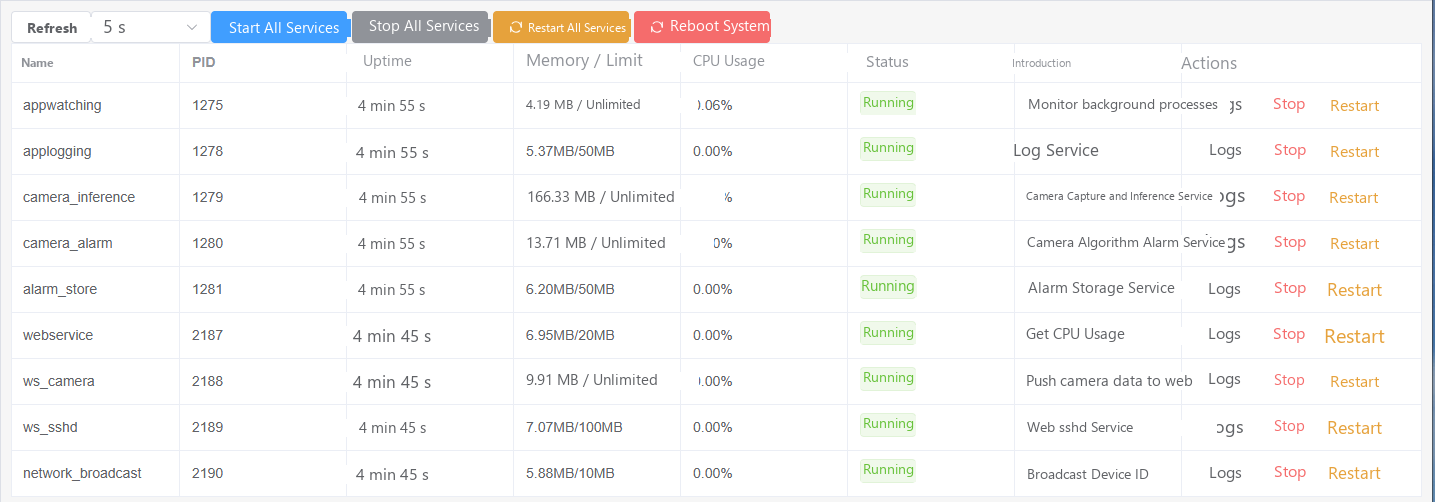
The processes listed are briefly described in the introduction column; hover over the text to see the full description.

2.9.2 Application Upgrade
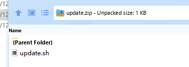
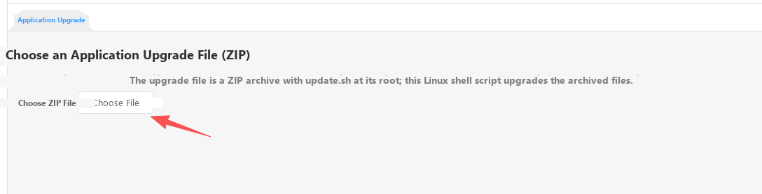
The application upgrade page simply requires a ZIP archive that meets the requirements: the archive root must contain an update.sh script, which performs the upgrade steps. This makes the mechanism generic — besides upgrading the web management program, it can upgrade any other application.
As a minimal test, write this into update.sh:
echo "OK" > /tmp/test_upgrade.txt
Then compress update.sh into a ZIP file:
On the page, click Choose File:
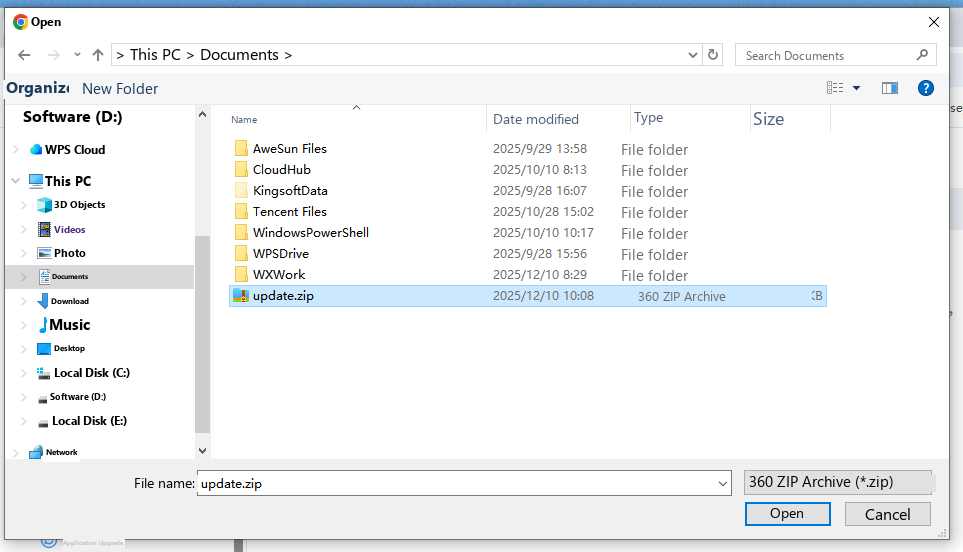
Select update.zip and click Open:
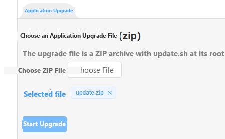
Click Start Upgrade; a success message appears:
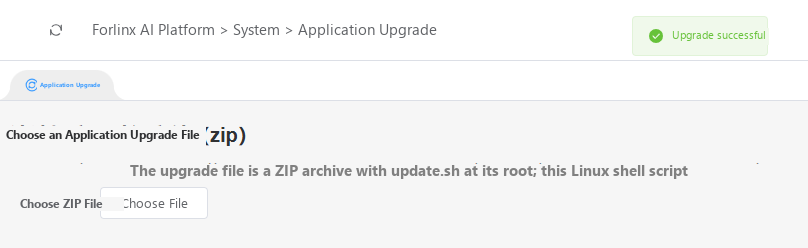
On the device’s shell, run cat /tmp/update.log:
OK
This confirms that update.sh ran correctly on the Linux side.
Note: the web management interface runs with root privileges, so anything update.sh does must be safe and controlled — it must not damage system files.
2.10 System
2.10.1 System Settings
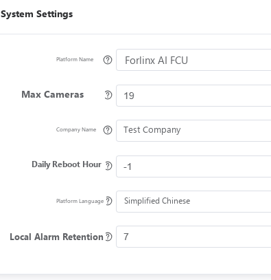
The system settings page has four tabs: System Settings, Export Configuration, Import Configuration, and Backup List.
1. System Settings
Here you can set the platform name, device model, company name, and the daily reboot time. If a daily reboot is not needed, set the reboot time to -1.
After changing a setting, a Save button appears next to the field; click it to apply the change.
2. Export Configuration
Click the Export Configuration tab:
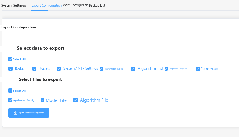
What can be exported:
Data
Data-type items generally map to a table in /web/data/web.db.
Item |
Description |
|---|---|
Roles |
The role table — all roles maintained under Users → Role Management. Usually selected together with Users. |
Users |
The user table — all users maintained under Users → User Management. Usually selected together with Roles. |
System / NTP settings |
Settings from System → System Settings and the NTP synchronization settings on System → System Time are stored in the same table. |
Parameter types |
Information maintained on Algorithms → Parameter Types. |
Algorithm list |
Information maintained on Algorithms → Algorithm List. |
Algorithm categories |
Information maintained on Algorithms → Algorithm Categories. |
Cameras |
Information maintained on Cameras → Camera List. |
Files
Item |
Description |
|---|---|
Application config |
|
Model files |
|
Algorithm files |
|
In short, the export covers a set of database tables and a few directories. Only configuration is exported; alarm records cannot be exported.
To export, tick the items you need (or keep the default select-all), then click Export Selected Configuration. The browser downloads a ZIP file, which can be imported on another device through Import Configuration.
3. Import Configuration
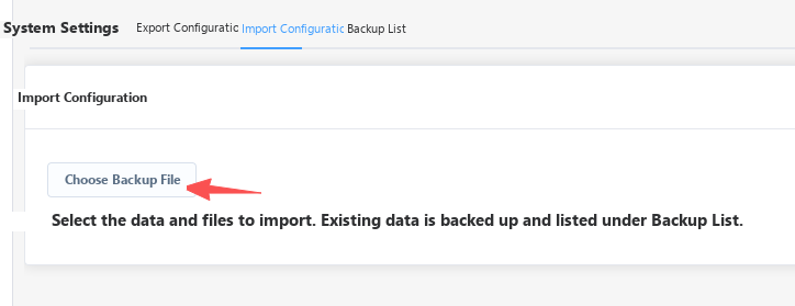
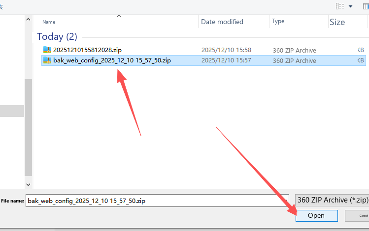
Click the Import Configuration tab, then Choose Backup File to open the file picker. Select an exported configuration (ZIP) and click Open:
The page shows which items the archive contains:
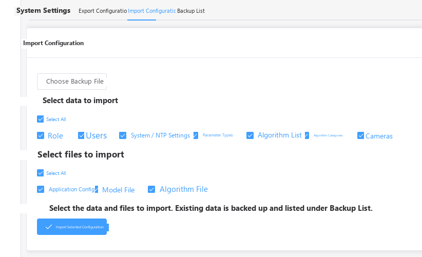
Items that were not selected during export are greyed out and cannot be imported.
2.10.2 System Resources
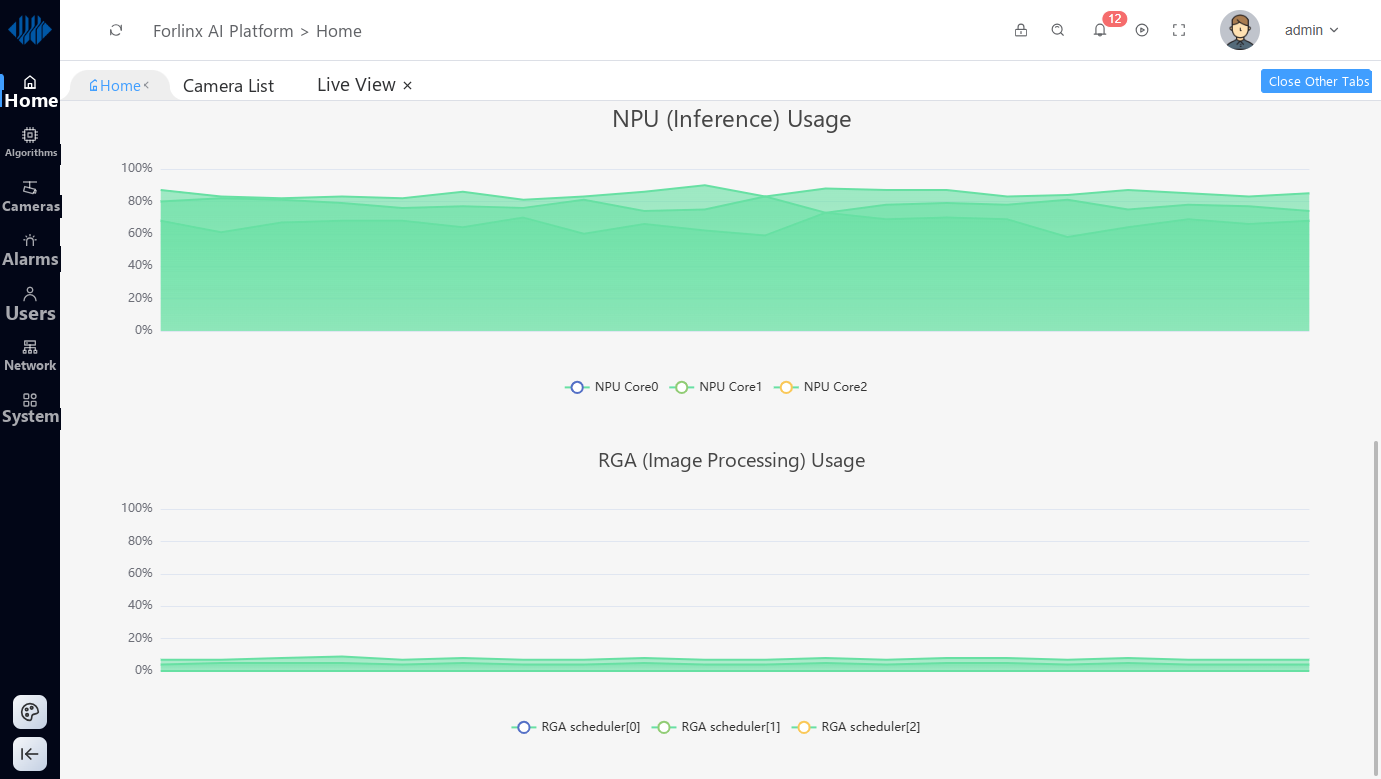
The system resources page shows the running state of the system in sections: system information, resource usage, wired network, wireless network, and CPU utilization.
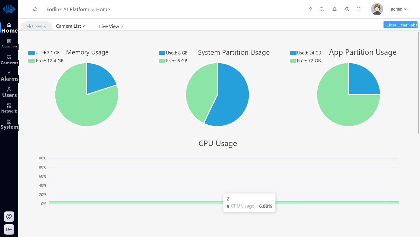
CPU, NPU, and RGA utilization curves update periodically, so after leaving the page open for a while you can see how resource usage fluctuates over time.
2.10.3 System Time
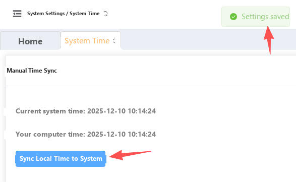
System time can be set from the web interface, or configured to synchronize periodically over NTP (the device must be able to reach an NTP server).
For manual synchronization, simply click Synchronize Local Time to System:
If the device has internet access, or a standard NTP server is available on the local network, configure NTP synchronization:
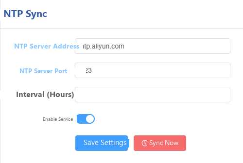
Make sure Enable Service is selected. Otherwise the configuration only supports manual synchronization — the background webservice process will not synchronize at the configured interval (in hours).
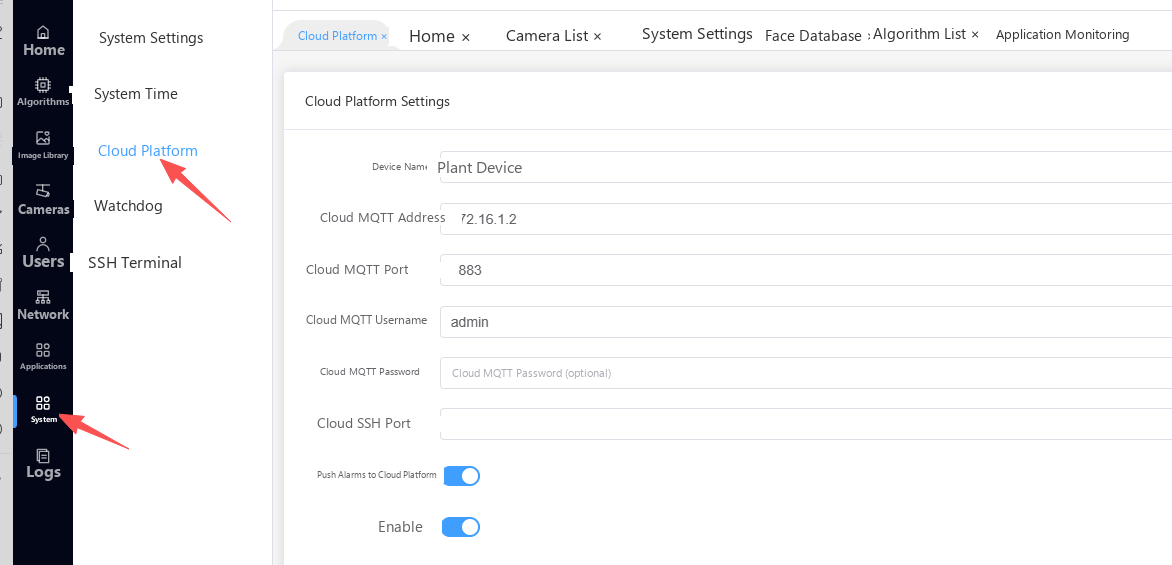
2.10.4 Cloud Platform
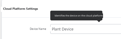
Hover over a field to see a tooltip:
The device name, cloud platform SSH port, and “push alarms to cloud platform” settings do not affect MQTT communication between the device and the cloud platform, so they can be changed freely on the cloud side.
Note: the cloud platform SSH port must be the one provided by the cloud platform’s host machine (not the port inside a Docker container), and the device’s public key must be deployed on the cloud platform during setup. Otherwise alarm images, model files, and algorithm files cannot be transferred.
2.10.5 Sound Column Settings
The system can send alarm announcements to a Paike sound column. You first need to purchase the speaker; the Tmall store is at https://danmaipaike.tmall.com/. When ordering, tell the seller that it is for “BH integration” (or add “BH integration” in the order notes) — the speaker’s built-in firmware provides the API this system connects to.
When the speaker arrives, ask support for the documentation link, follow the document to install the software and set the speaker’s IP address, and make sure the AI system can ping that IP. Then open the sound column settings page:
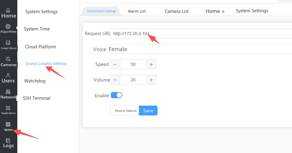
Enter the sound column URL, select Enable, and click Save. From then on, when an alarm is raised, the sound column plays the announcement.
Note: the volume setting here controls the synthesized speech, and works together with the playback volume set on the device. During commissioning, set the playback volume on the device management page (http://<device-IP>:8080) as appropriate (100 in noisy environments, 50 in quiet ones), then set a suitable speech volume on this page.
The page exposes only part of the configuration; the remaining settings live in this file. body corresponds to the request body described in Direct LAN Integration with Speaker Devices — Text TTS and Media URL Playback API (Speaker Integration). Refer to that document for the parameter descriptions.
cat /web/bin/cfg/player.json
{
  "body": {
    "intercut": false,
    "prompt": false,
    "queue": true,
    "rcn": "0",
    "rdn": "0",
    "reg": 0,
    "speed": 50,
    "sync": false,
    "text": "",
    "vcn": "xiaoyan",
    "volume": 25
  },
  "enabled": false,
  "password": "888888",
  "url": "http://172.20.0.104"
}
2.10.6 Watchdog
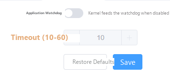
The watchdog can be configured to be fed either by an application or by the kernel. With application feeding enabled, the appwatching process feeds the watchdog periodically; if appwatching exits unexpectedly, the system restarts automatically once the timeout (in seconds) expires.
If another application should feed the watchdog instead, disable application feeding here and manage it from that application.
2.11 Logs
2.11.1 Application Logs
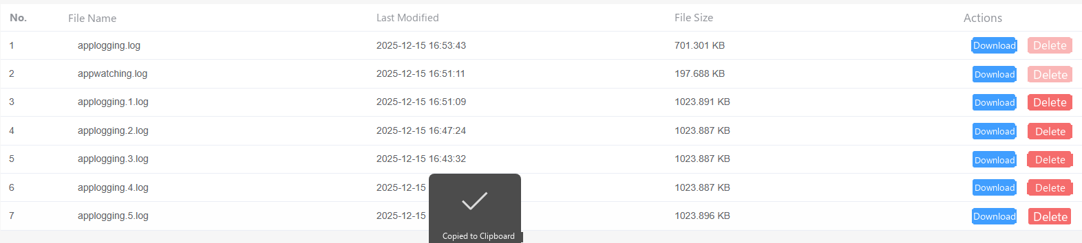
Application logs give access to every file in /web/bin/log. By default this directory holds the logs of appwatching, applogging, and the Wi-Fi connection.
2.11.2 Operation Logs
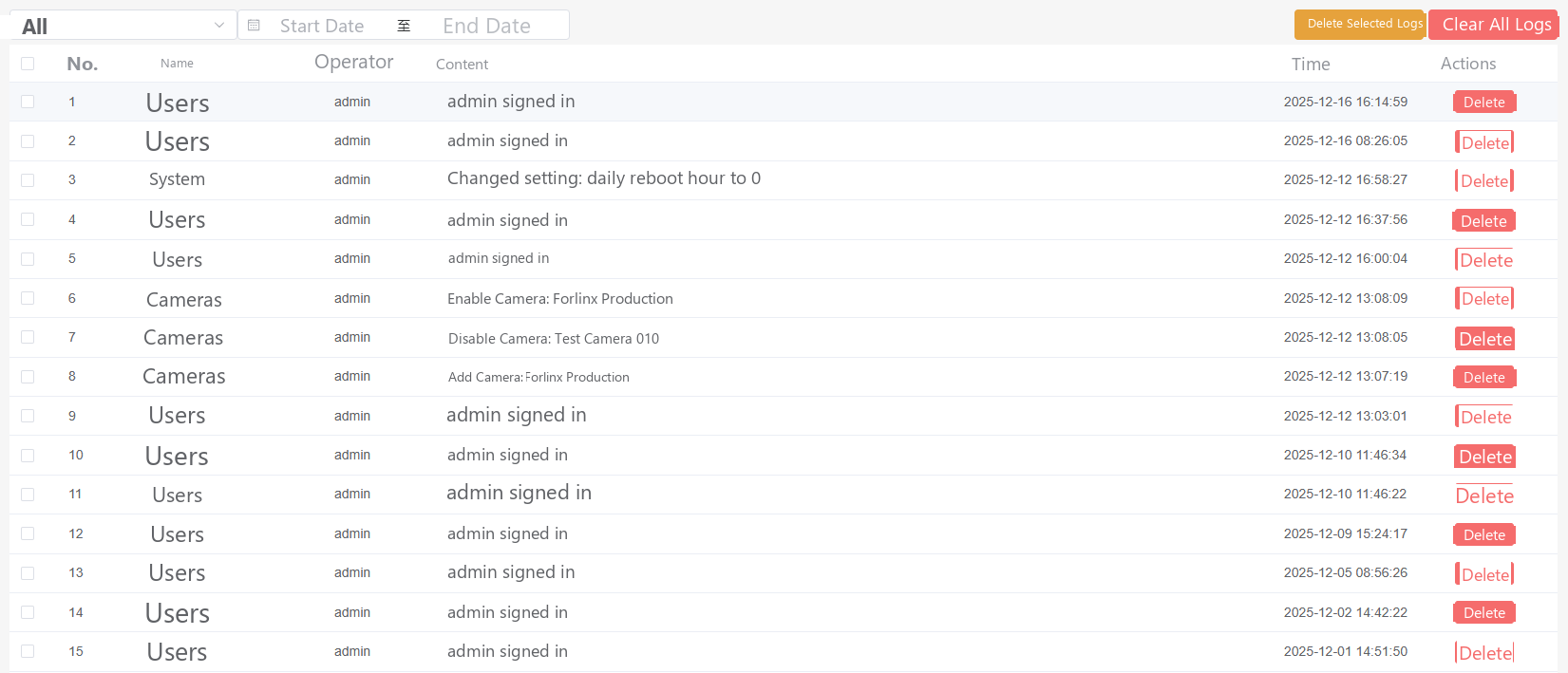
The operation log records the key actions users perform in the web interface. Records can be deleted individually or cleared entirely.
3. Algorithm Reference
All object-detection algorithms assume a bright scene, a clear target, and a target occupying at least 10% of the frame. A dirty lens, a cluttered scene, occlusion, dim light, or a very small target will all reduce detection accuracy.
Nearly all detection algorithms share the following standard parameters:
Parameter |
Description |
|---|---|
Confidence |
The minimum confidence for a detection to count; targets below this value are ignored. |
Detection window |
Used together with the alarm threshold. |
Alarm threshold |
The number of hits required within a detection window before an alarm can be raised. With a window of 5 and a threshold of 3, at least 3 of the 5 inference results sent to the alarm program must match the alarm rule (note the camera’s inference rate). Whether the alarm is actually stored and pushed as a live alarm is then decided by the alarm interval. |
Alarm interval |
The minimum time between two alarms. If the previous alarm is more recent than this interval, no new alarm is raised. |
FCU3101 ships with the 17 AI algorithms listed below; more are being added.
Category |
No. |
Algorithm |
Description |
|---|---|---|---|
Safety |
1 |
Smoke detection |
Scene: outdoor, indoor, industrial site. |
Safety |
2 |
Open flame detection |
Scene: outdoor, indoor, industrial site. |
Personnel |
3 |
Hard hat detection |
Scene: outdoor, indoor, industrial site. |
Personnel |
4 |
High-visibility vest detection |
Scene: outdoor, indoor, industrial site. |
Personnel |
5 |
Smoking detection |
Scene: outdoor, indoor, industrial site. |
Personnel |
6 |
Phone use detection |
Scene: outdoor, indoor, industrial site. |
Personnel |
7 |
Fall detection |
Scene: outdoor, indoor, industrial site. |
Personnel |
8 |
Intrusion detection |
Scene: outdoor, indoor, industrial site. |
Personnel |
9 |
Absence-from-post detection |
Scene: outdoor, indoor, industrial site. |
Personnel |
10 |
Loitering detection |
Scene: outdoor, indoor, industrial site. |
Personnel |
11 |
Dwelling detection |
Scene: outdoor, indoor, industrial site. |
Personnel |
12 |
Sleeping-on-duty detection |
Scene: outdoor, indoor, industrial site. |
Personnel |
13 |
Crowd gathering detection |
Scene: outdoor, indoor, industrial site. |
Personnel |
14 |
People counting |
Scene: outdoor, indoor, industrial site. |
Vehicles |
15 |
License plate recognition |
Scene: outdoor, industrial site. |
Vehicles |
16 |
License plate color recognition |
Scene: outdoor, industrial site. |
Environment |
17 |
Garbage detection |
Scene: outdoor, indoor, industrial site. |