Android11.0_User’s Manual_V2.2
Document classification: □ Top secret □ Secret □ Internal information ■ Open
Copyright
The copyright of this manual belongs to Baoding Folinx Embedded Technology Co., Ltd. Without the written permission of our company, no organizations or individuals have the right to copy, distribute, or reproduce any part of this manual in any form, and violators will be held legally responsible.
Forlinx adheres to copyrights of all graphics and texts used in all publications in original or license-free forms.
The drivers and utilities used for the components are subject to the copyrights of the respective manufacturers. The license conditions of the respective manufacturer are to be adhered to. Related license expenses for the operating system and applications should be calculated/declared separately by the related party or its representatives.
Revision History
Date |
User Manual Version |
Revision History |
|---|---|---|
27/05/2022 |
V1.0 |
OK3568-CAndroid11.0User’s Manual Initial Version |
23/09/2022 |
V1.1 |
1.Modifying the Uboot menu and adding the description of rgb; |
29/05/2023 |
V1.2 |
Adding the description of ov13850 support in 3.22.2 MIPI Camera test section. |
22/08/2023 |
V1.3 |
1. Adding can standard frame and extended frame descriptions; |
21/05/2024 |
V2.0 |
Adding FET3568-C2 SoM. |
18/07/2025 |
V2.1 |
Adding CXMT memory description in section 3.15 key test (sleep wake) and removing sleep wake function. |
20/10/2025 |
V2.2 |
Adding notes in the WIFI test chapter and the quick startup chapter (the antenna must be connected for startup, otherwise the startup may be affected). |
Overview
This manual is designed to help you quickly familiarize yourselves with the product, and understand the interface functions and testing methods. It primarily covers the testing of interface functions on the development board, the methods for flashing images, and troubleshooting procedures for common issues encountered in use. In the process of testing, some commands are annotated to facilitate the your understanding, mainly for practical use. Please refer to the “OK3568-C Compilation Manual” provided by Forlinx for the kernel compilation, compilation method, development environment building.
The manual is primarily divided into five chapters:
Chapter 1. focuses on the overall overview of the product, and briefly introduces the development board in the interface resources, the relevant driver path in the kernel source code, and the description of the key parts of the information;
Chapter 2. covers quick startup of the product, with options for both serial port login and network login;
Chapter 3. mainly serves as an introduction to the product’s usage features and is divided into multiple sections, including the function testing of the command line in the terminal and the function testing of the QT desktop;
Chapter 4. mainly focuses on testing the usage of the product’s features such as audio, video, and camera;
Chapter 5. focuses on the product’s image update, mainly describing the method of updating the image to the storage device, and users can choose the corresponding flashing method according to the actual situation.
A description of some of the symbols and formats associated with this manual:
Format |
Meaning |
|---|---|
Note |
Note or information that requires special attention, be sure to read carefully. |
📚 |
Relevant notes on the test chapters. |
🛤️ |
Indicates the related path. |
Blue font on gray background |
Refers to commands entered at the command line (Manual input required). |
Black font |
Serial port output message after entering a command. |
Bold black |
Key information in the serial port output message. |
// |
Interpretation of input instructions or output information. |
Username@Hostname |
root@ok3568: development board serial port login account information; |
After packaging the file system, you can use the “ls” command to view the generated files.
forlinx@ubuntu:~/3568$ ls                              //List the files in this directory
OK3568-linux-source  OK3568-linux-source.tar.bz2
forlinx@ubuntu: the username is forlinx and the hostname is ubuntu, indicating that the operation is performed in the development environment ubuntu.
//: Explanation of operation commands is required, but command input is not needed.
ls: blue font on a gray background, indicating relevant commands that need to be entered manually.
OK3568-linux-source: Black font is the output information after entering the command; bold font is the key information; here is the packaged file system.
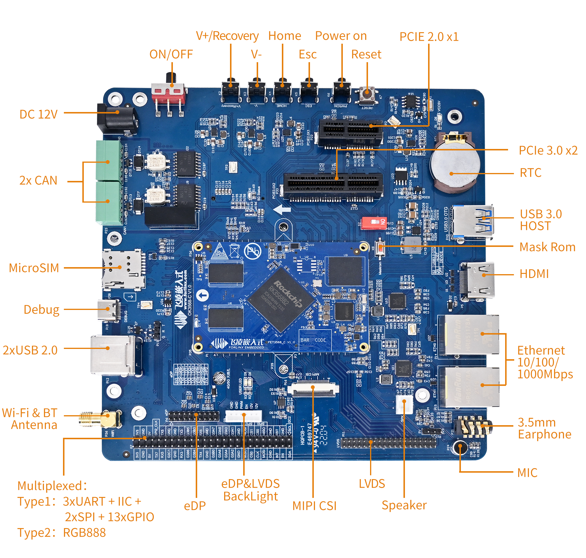
1. OK3568-C Development Board Description
1.1 OK3568-C/OK3568-C2 Development Board Description
RK3568 is a low-power high-performance processor based on ARM64 architecture. It includes 4-core Cortex-A55 and independent NEON co-processor and neural network plus processor NPU. It can be applied to computers, mobile phones, personal mobile Internet and digital multimedia devices.
The connection between SoM and the carrier board is board-to-board, and the main interfaces are shown as follows:
Note:
Hardware parameters are not described in this software manual. Before referring to this manual for software development, please read “OK3568-C_ Hardware Manual_V1.0-2022.02.09” under the path of “Hardware Data \ User Manual” to understand the product naming rules and the hardware configuration information of the product you use, which is helpful for you to use this product.
1.2 Android11 System Software Resources Features
Device |
Location of driver source code in the kernel |
Device Name |
|---|---|---|
LCD Backlight Driver |
drivers/video/backlight/pwm_bl.c |
/sys/class/backlight |
USB Port |
drivers/usb/storage/ |
|
USB Mouse |
drivers/hid/usbhid/ |
/dev/input/mice |
Ethernet |
drivers/net/ethernet/stmicro/stmmac |
|
SD/micro TF card driver |
drivers/mmc/host/dw_mmc-rockchip.c |
/dev/block/mmcblk1pX |
EMMC Driver |
drivers/mmc/host/dw_mmc-rockchip.c |
/dev/block/mmcblk2pX |
OV13850 |
drivers/media/i2c/ov13850.c |
/dev/videoX |
LCD Controller |
drivers/gpu/drm/rockchip/rockchip_drm_vop.c |
|
MIPI CSI |
drivers/phy/rockchip/phy-rockchip-mipi-rx.c |
|
MIPI DSI |
drivers/phy/rockchip/phy-rockchip-inno-mipi-dphy.c |
|
LCD Touch Driver |
drivers/input/touchscreen/gt9xx/* |
/dev/input/eventX |
RTC Real Time Clock Driver |
drivers/rtc/rtc-rx8010.c |
/dev/rtc0 |
serial port |
drivers/tty/serial/8250/8250_dw.c |
/dev/ttySX |
Key Driver |
drivers/input/keyboard/adc-keys.c |
/dev/input/eventX |
LED |
drivers/leds/leds-gpio.c |
|
I2S |
sound/soc/rockchip/rockchip_i2s.c |
|
Audio Driver |
sound/soc/codecs/rk817_codec.c |
/dev/snd/ |
PMIC |
drivers/mfd/rk808.c |
|
PCIE |
drivers/pci/controller/pcie-rockchip.c |
|
Watchdog |
drivers/watchdog/dw_wdt.c |
|
SPI |
drivers/spi/spi-rockchip.c |
|
PWM |
drivers/video/backlight/pwm_bl.c |
1.3 EMMC Memory Partition Table
The following table is the eMMC memory partition information of Android operating system (the size of a block is 512bit when calculating):
Partition Index |
Name |
Offset / Block |
Size/Block |
Content |
|---|---|---|---|---|
N/A |
security |
0x00002000 |
0x00002000 |
MiniLoaderAll.bin |
1 |
uboot |
0x00004000 |
0x00002000 |
uboot.img |
2 |
trust |
0x00006000 |
0x00002000 |
|
3 |
misc |
0x00008000 |
0x00002000 |
misc.img |
4 |
dtbo |
0x0000a000 |
0x00002000 |
dtbo.img |
5 |
vbmeta |
0x0000c000 |
0x00000800 |
vbmeta.img |
6 |
boot |
0x0000c800 |
0x00014000 |
boot.img |
7 |
recovery |
0x00020800 |
0x00030000 |
recovery.img |
8 |
backup |
0x00050800 |
0x000c0000 |
2. Fast Startup
2.1 Preparation Before Startup
12V2A or 12V3A DC Power Cable
Debugging serial cable
Note: Be sure to install the WiFi antenna when startup.
The debugging serial port on the development board is a Micro USB Jack. You can use the USB to micro cable to connect the development board and the PC, so as to view the status of the development board.
2.2 Debugging Serial Driver Installation
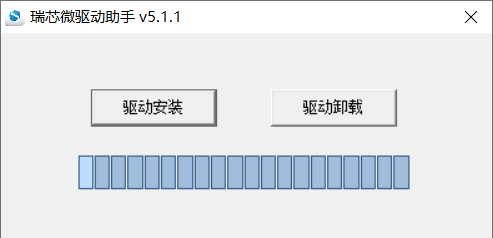
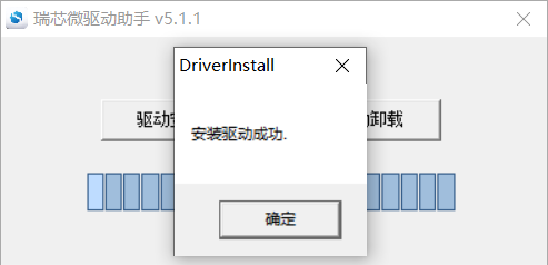
OK3568-C/OK3568-C2 platform uses a Type-C interface for debugging serial port, with an on-board USB to UART chip. Customers do not need to purchase USB to serial debugging tools; it is extremely simple and convenient to use.
To install the driver, please use the driver package DriverAssitant_v5.11.zip provided in the User Profile \Android\Tools\ directory.
Run DriverInstall.exe directly after the unzipping is completed; in order to ensure the driver is the latest version, please unstall the driver first, then install again.
2.3 Serial Port Login
2.3.1 Serial Port Connection Settings
Note:
Serial port terminal login user: Serial port terminal automatically logs in root user without password;
Serial port settings: Baud rate 115200, 8 data bits, 1 stop bit, no parity bit, no flow control;
Hardware Requirements: Type-C cable required to connect PC and development boards;
Software requirements: PC Windows system needs to install the super terminal software. Because the terminal software has many types, users can choose their familiar one.
In the following, we take the putty terminal software as an example to introduce the serial port login method:
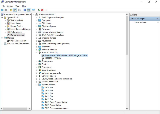
Step 1: Connect the serial port number of the computer—check the serial port number from the device manager (Based on the port actually recognized by the computer );
Step 2: Open and set up putty, then set the“ line according to the COM port of the computer used, baud rate 115200;
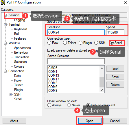
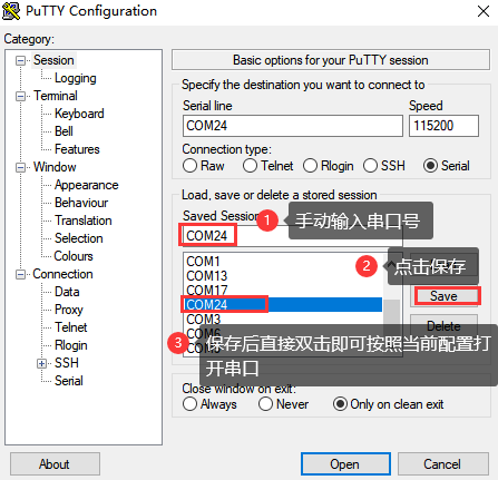
Step 3: After the setting, input the COM port used by the computer in Saved Sessions. The following figure takes COM3 as an example, save the settings, open the serial port again later, and click on the saved port number;
2.3.2 Serial Login
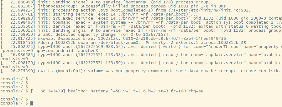
After the terminal software on the PC side is set, connect the PC and the development board through the serial port cable, and power on after connecting the power supply. The startup information can be seen through the terminal software.
The following startup message indicates a successful start, allowing a new command line to be entered by pressing Enter:
2.4 Screen Switching
OK3568 supports multi-screen interfaces such as MIPI DSI, HDMI, eDP, etc. Currently there are two methods for controlling screen switching: specifying through the device tree in the kernel and dynamically controlling through the Uboot menu.
Note:
RGB screen resolution defaults to 1024x600. When using the rgb screen, the sleep wake function cannot be used;
Screen switching involves touch switching. The factory image defaults to outputting video display on LVDS, MIPI, and HDMI interfaces simultaneously, with touch functionality on LVDS screen. If using MIPI touch, please turn off LVDS screen output during the screen selection process.
2.4.2 Kernel Device Tree Specification
This method does not require the connection of a serial terminal, and the system image defaults to the desired configuration selection, which is suitable for mass production. However, we need to manually modify the device tree and regenerate the system image once again
Note: This method has higher priority than the uboot screen selection, and the uboot selection will not take effect after the device tree is modified.
Device tree path:kernel/arch/arm64/boot/dts/rockchip/OK3568-C-common.dtsi
In the kernel source code, open the device dtsi file and find the following node:
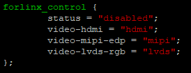
The node has a default disabled state and needs to be changed to an okay enabled node. Change according to screen requirements.
Examples:
Close the hdmi, lvds screens, change the attribute to “off”, and use edp to change the corresponding attribute to edp.
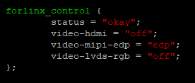
After saving, recompile to generate the image.
There are many types of MIPI screens, and the existing timing and control words may not meet the requirements, so it is necessary to change the display-timings under the dsi node. However, any node status attribute related to display is handled by default, and the program will automatically control it.
2.5 System Shutdown
In general, you can turn off the power directly, but avoid doing so during important operations like data storage or usage to prevent irreversible file damage. Damaged files may require firmware rewrite. To ensure that data is not completely written, enter sync command to complete data synchronization before turning off the power.
Note: If the user-designed product using the SoM experiences an unexpected shutdown due to power loss during operation, power-down protection measures can be included in the design to prevent this issue.
3. Android Function Use and Test
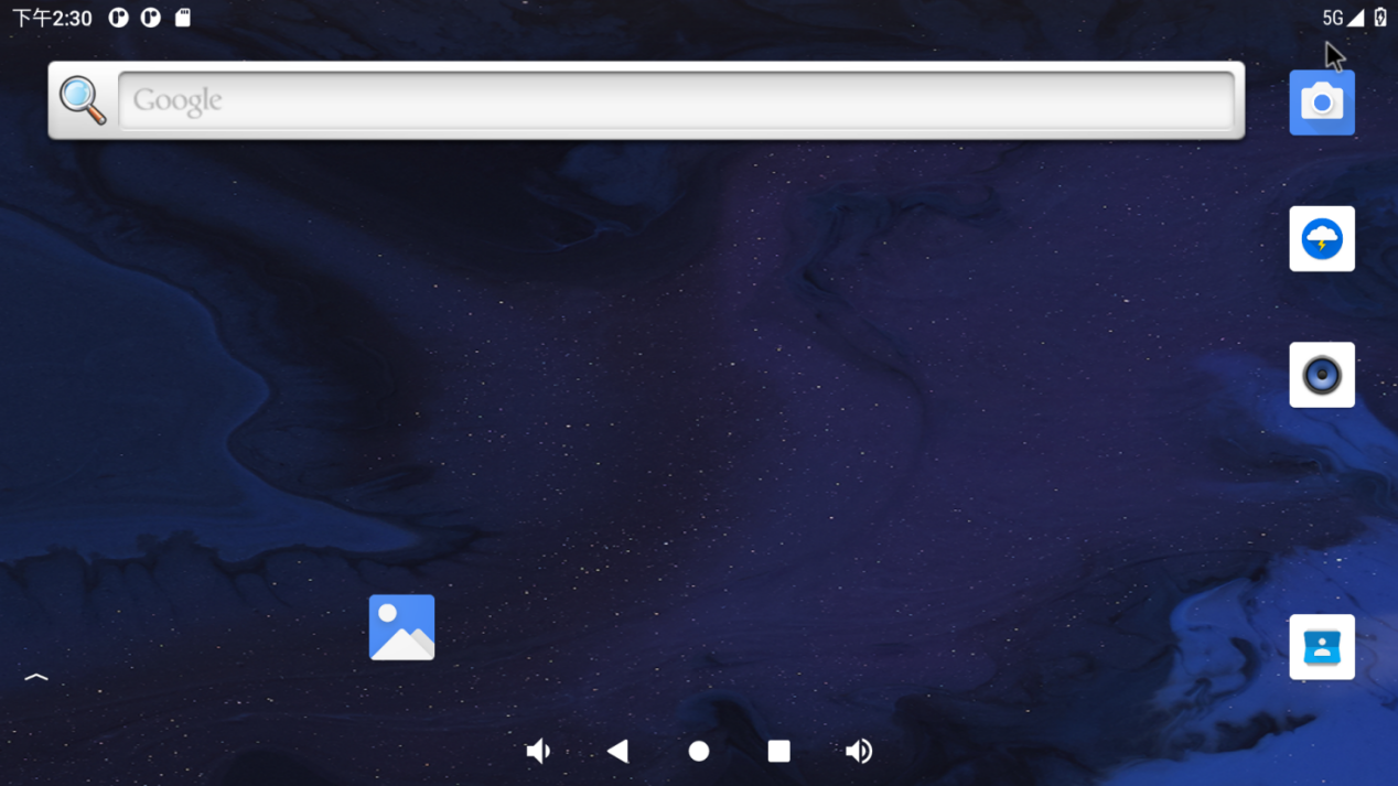
3.1 Main Interface Display
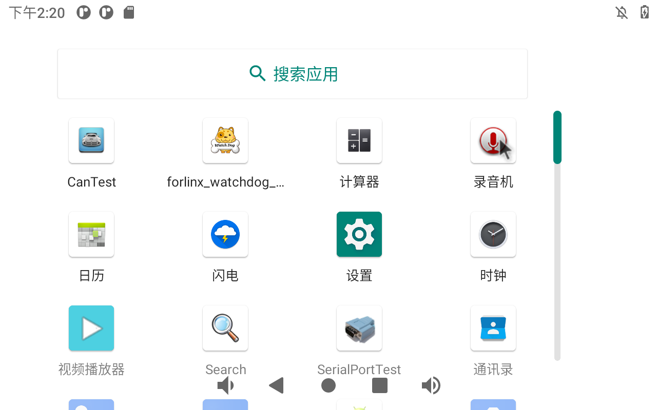
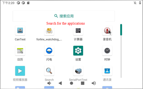
3.2 Application
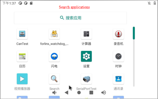
Swipe up on the main screen to bring up the following screen.
Note: There may be slight differences after the software version update is completed. It is not used as the actual picture after each version update in the future. It is only for reference.
3.3 Language Settings
Click “ ”, on the application interface to enter the setting interface:

Click “ ” on the application interface to enter the system interface.
Click “Language and input method” to enter the language setting interface:
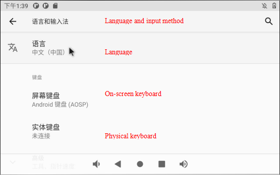
Click “Language” to enter the language selection interface:
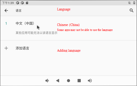
Click “Add Language” to add a new language.
If you want to remove an installed language, you can click the icon with three dots in the upper right corner, select Remove, check the language you want to delete, click the trash can icon in the upper right corner, and a dialog box pops up, “Do you want to remove the selected language?” Click “Confirm” to deleted the language.
3.4 Picture and Audio View
Store the picture and video files to be viewed into the TF card, and insert the TF card into the development board.
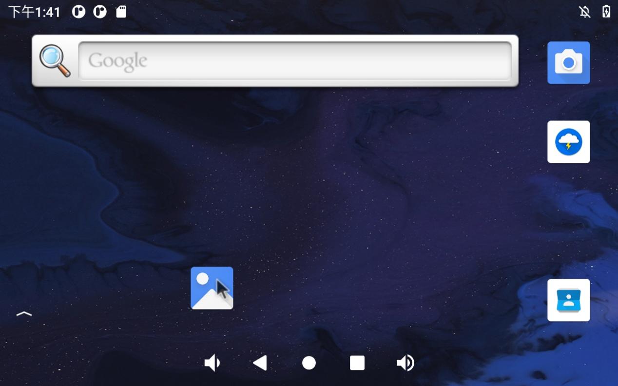
Click “ ” on the application interface to enter the TF card picture browsing interface.
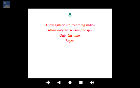
Configure permissions:
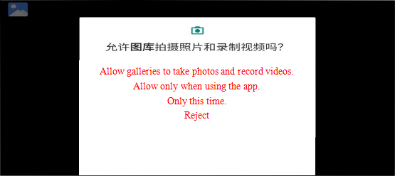
After configuration, enter the picture and video view:
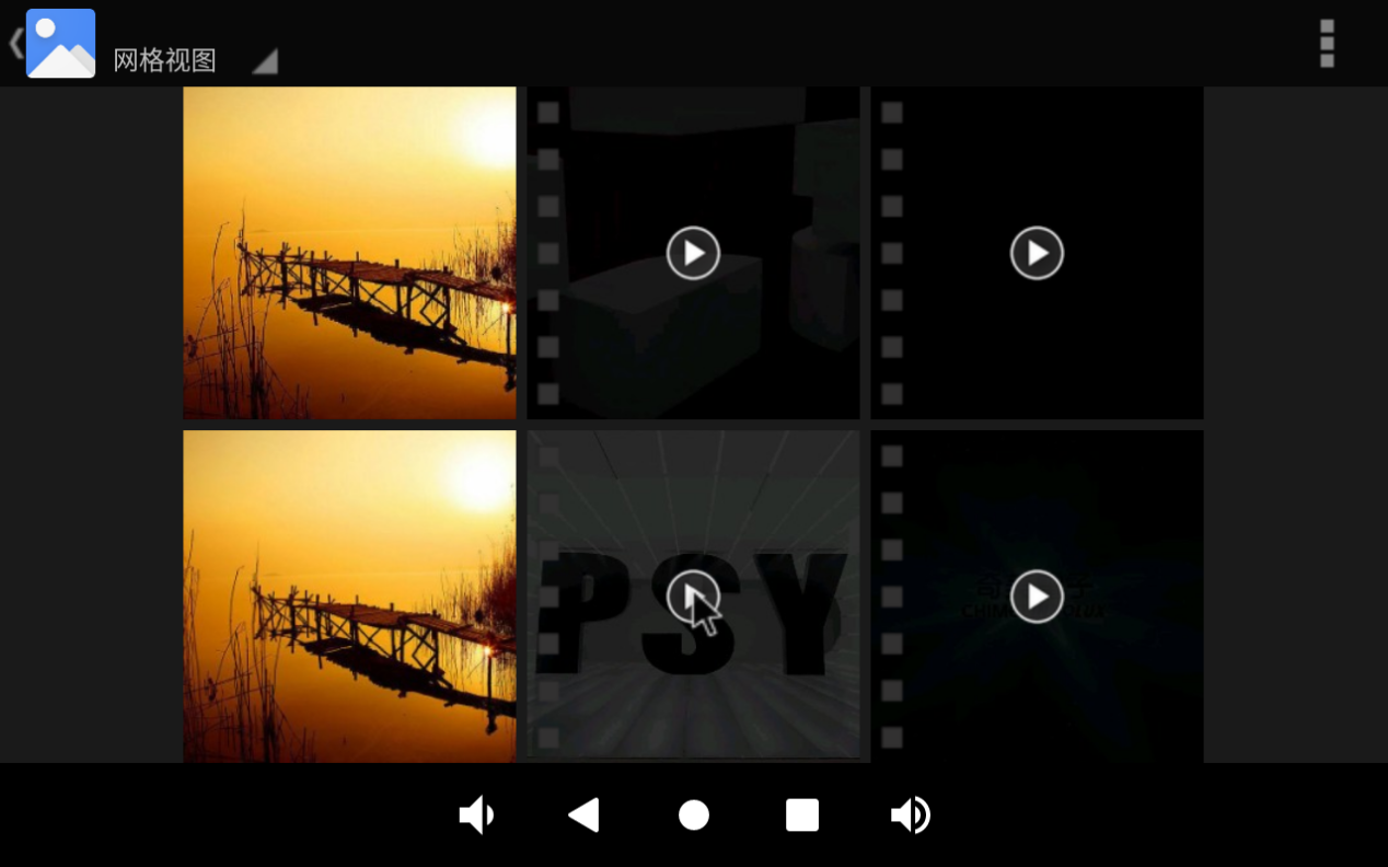
Click on the pictures and videos to view:

3.5 Multimedia Test
Store the audio file to be played into the TF card, and insert the TF card into the development board.
Click “ ” in the application interface to enter the music player interface.

Click “ ” in the interface to enter the song list interface.
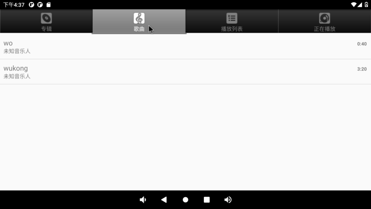
Click “Play Music” to enter the play interface.
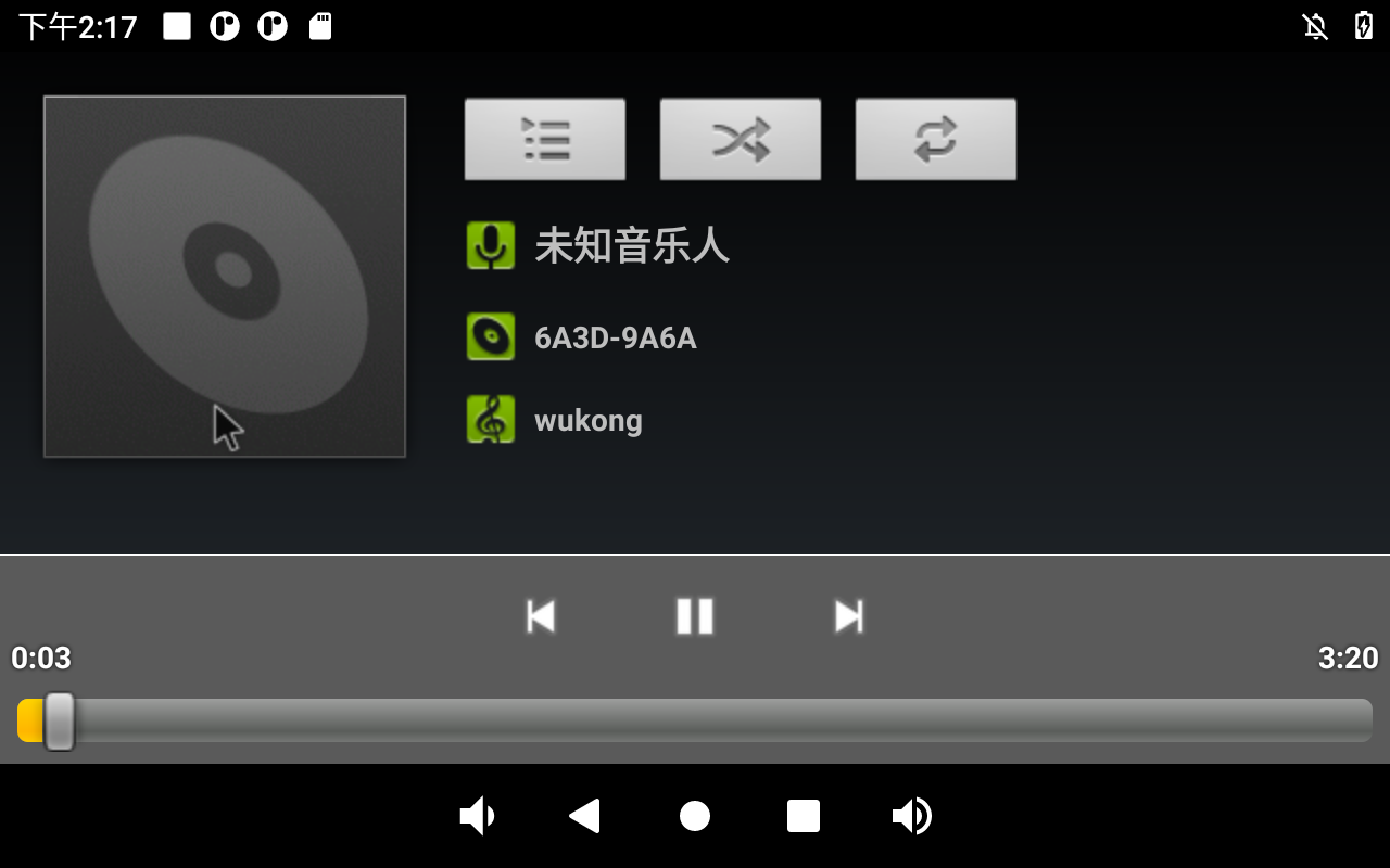
The priority of sound playback is headphone > HDMI audio > carrier board speaker, and the volume can be adjusted by pressing the physical keys VOL + and VOL- on the carrier board of the development board.
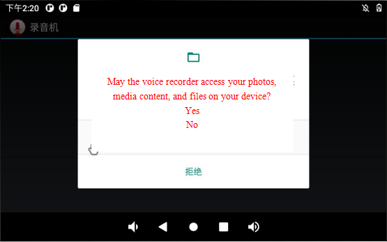
3.6 Recording (Supports Mic input)
Click the video “ ” in the application interface to enter the recorder interface:
Configure permissions:
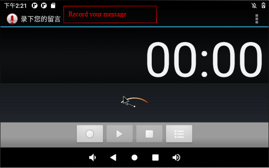
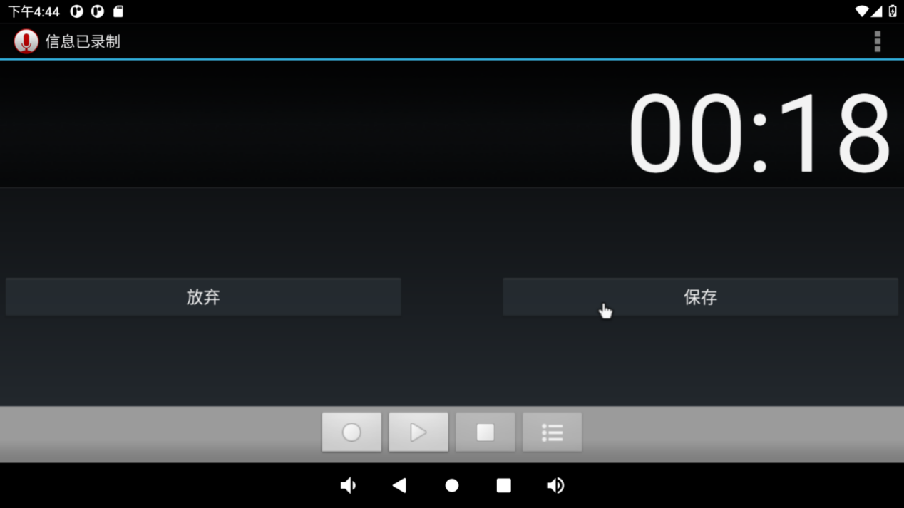
Click the round button to start recording: (Note: the pointer will swing according to the sound level during normal recording).
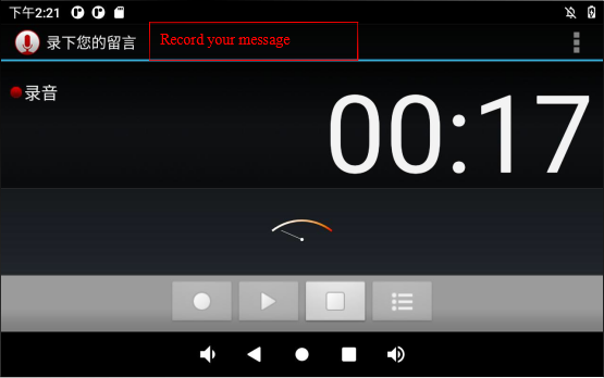
Click the square button to stop recording, and finally click the done button to save.
The recorded audio can be viewed and played through the music player. Click the playlist of the music player:
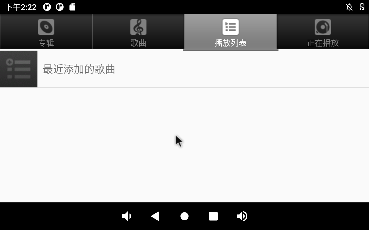
Click the recently added song to see the newly generated recording file:
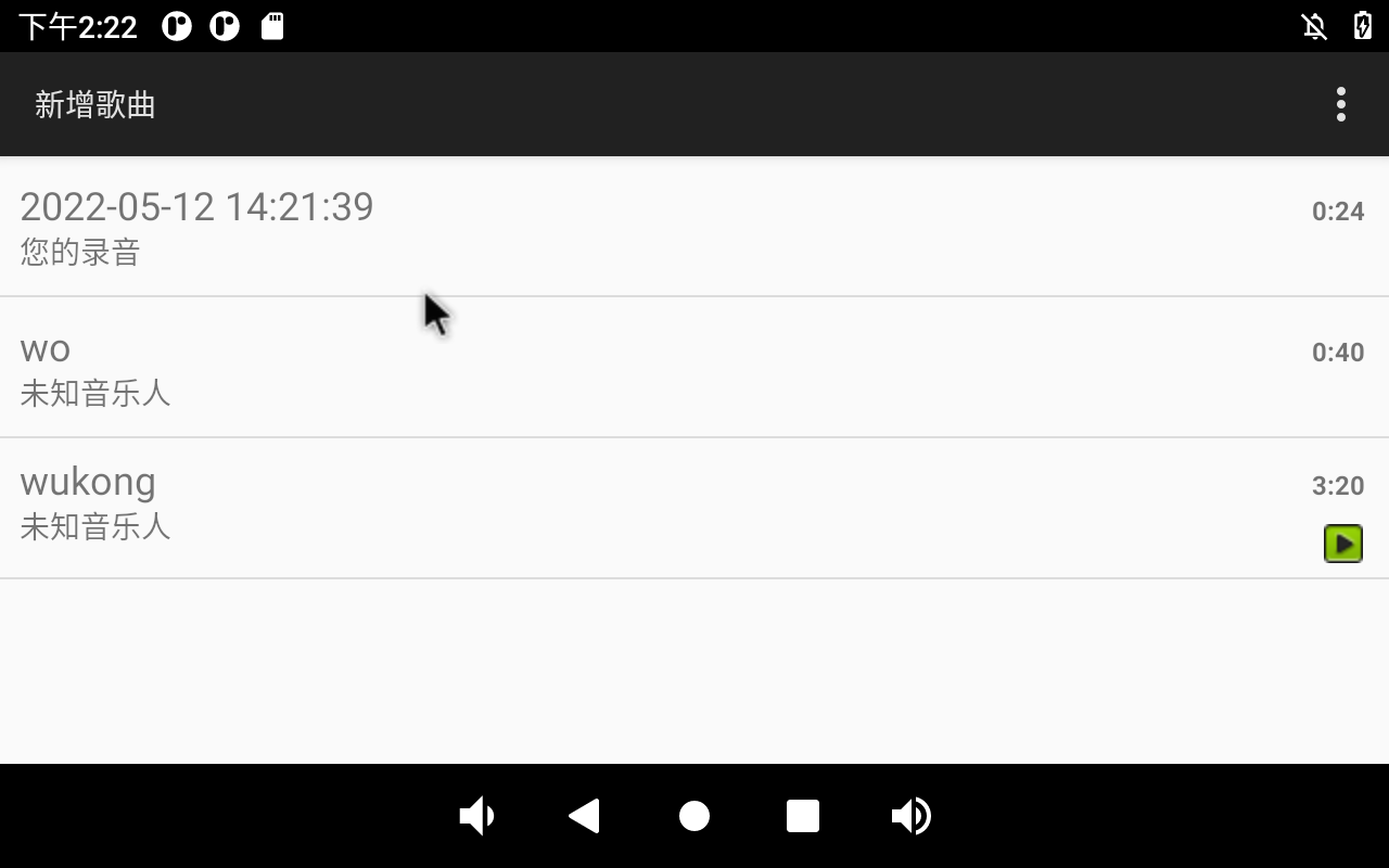
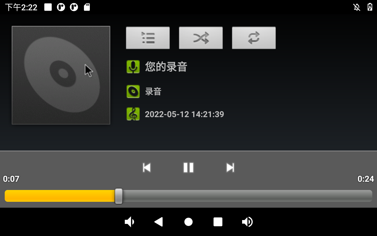
Click the file to play:
3.7 Volume Adjustment
Click “ ”, on the application interface to enter the setting interface:
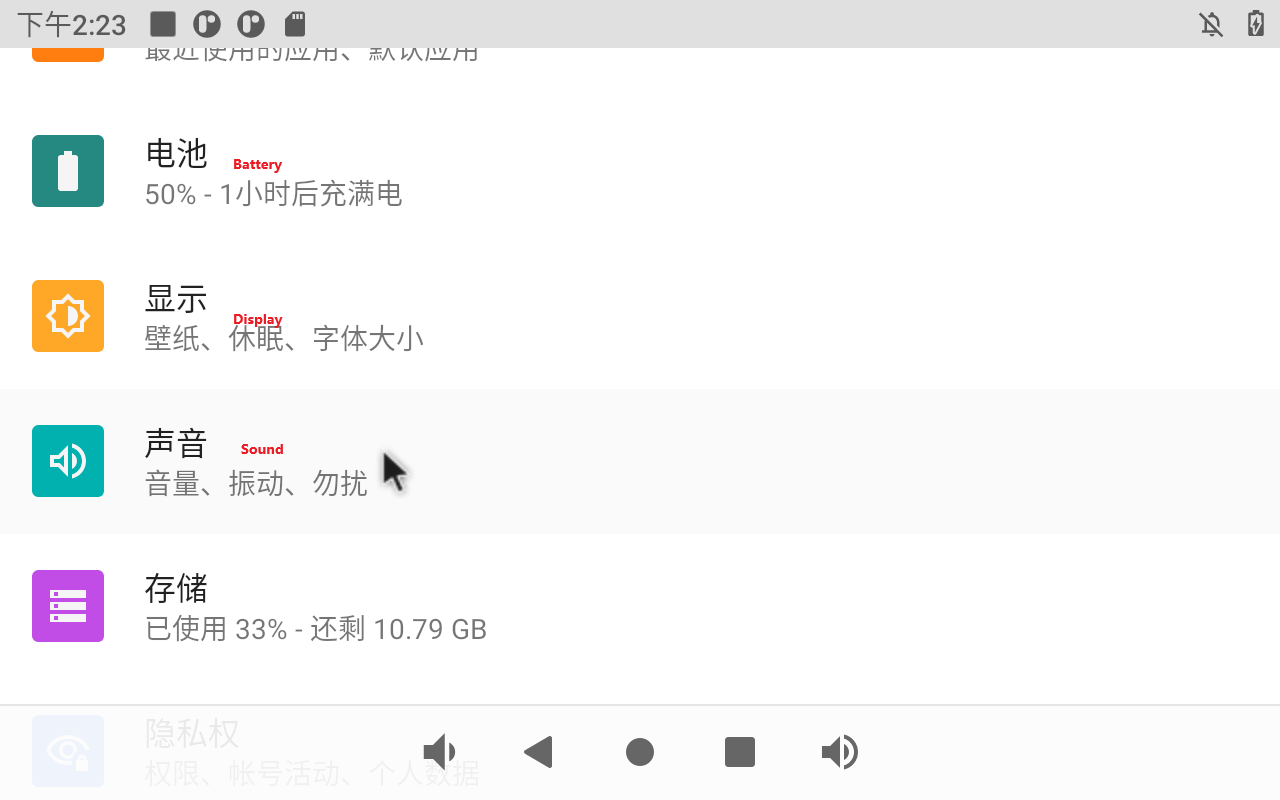
Click “Sound” in the settings interface to enter the volume settings interface.
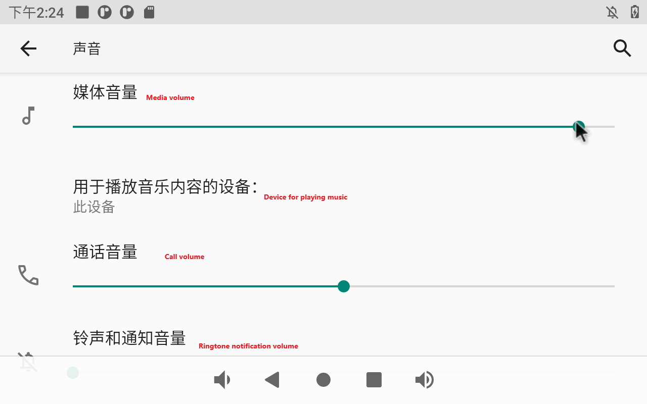
This interface allows you to adjust each section’s volume and supports media volume adjustment using the physical buttons VOL- and VOL+ on the base plate.
Click “Advanced” to set the ringtone of the mobile phone:

3.8 Display Settings
Click “ ”, on the application interface to enter the setting interface:
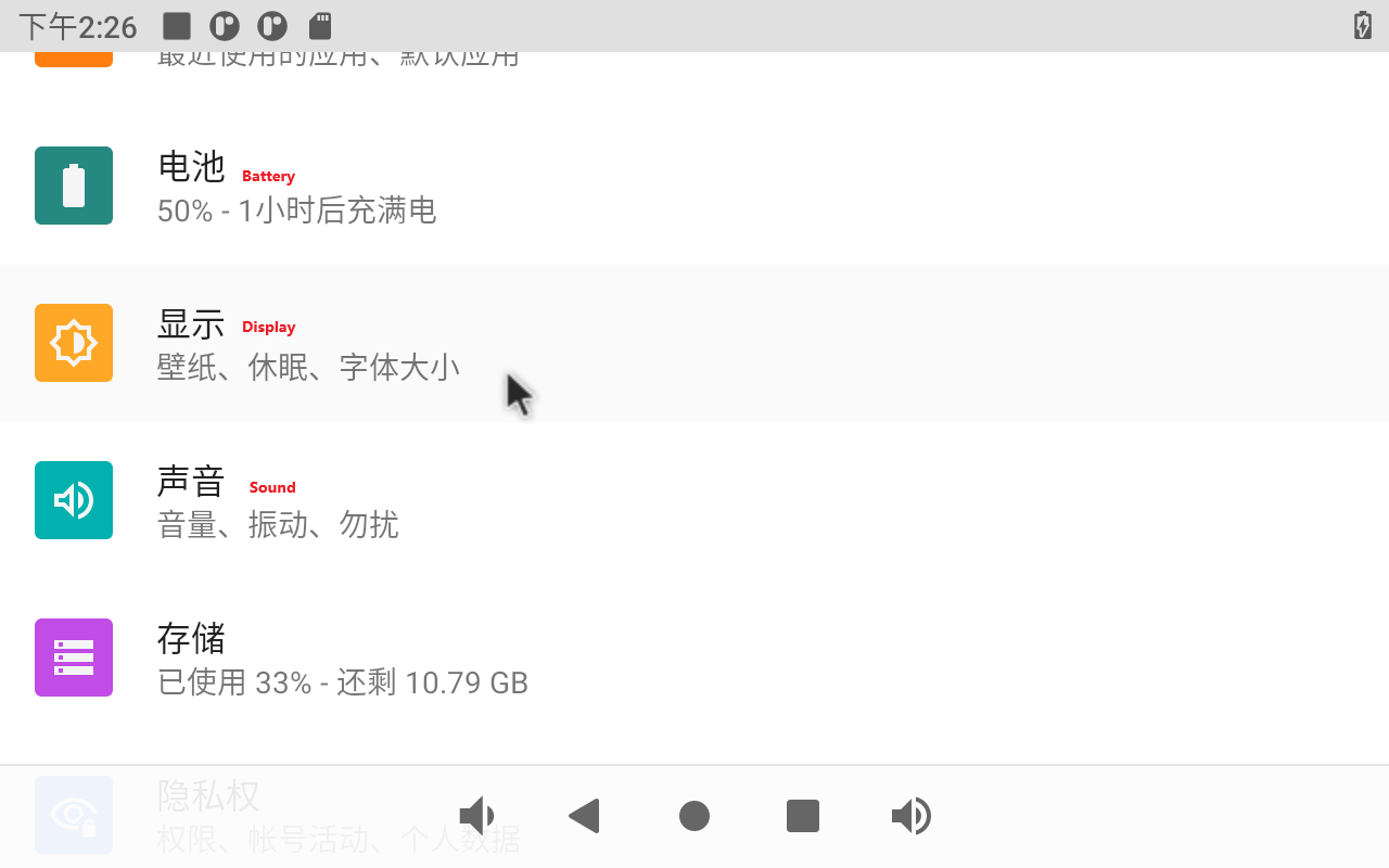
Click “Display” in the setting interface, enter the display setting interface, and select “Brightness” for the backlight setting, then the brightness adjustment slider will appear, adjust the brightness. Because the development board provided by Forlinx does not have a power sensing chip, the automatic screen rotation function in the advanced options does not work.
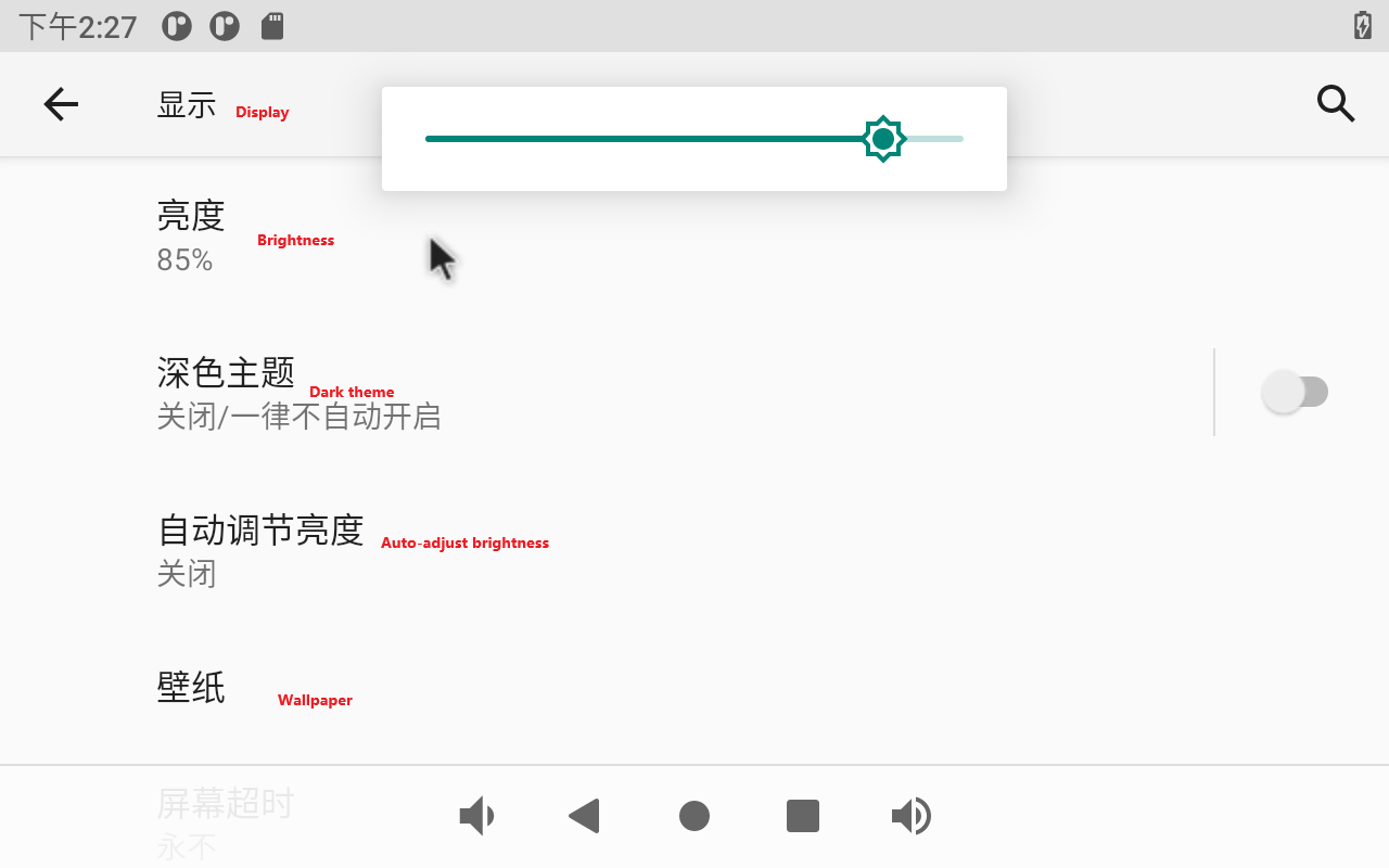
The default setting of OK3568 is to never turn off the screen. If you need to sleep and wake up, please click the “Screen timeout” option to select the sleep time.
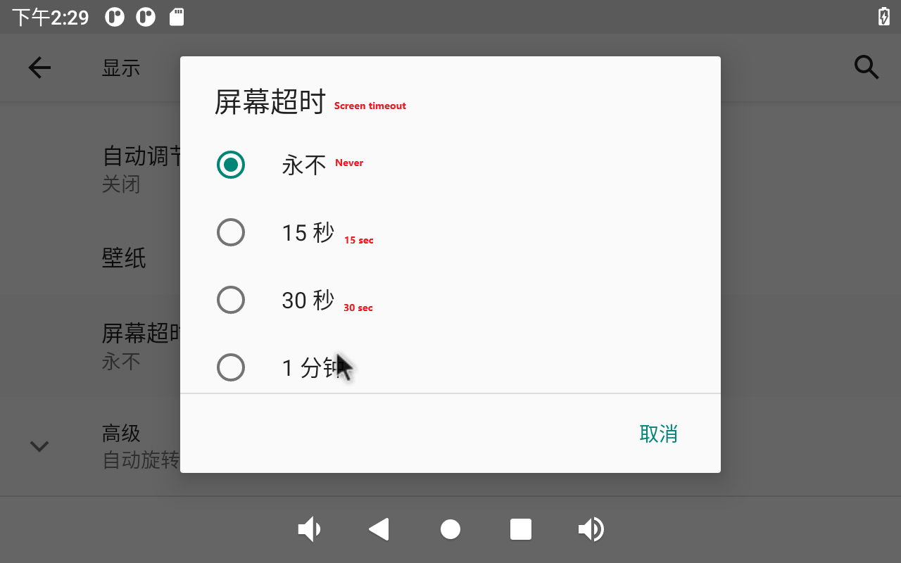
If there is no operation on the interface within the set sleep time, the screen will enter the sleep mode, and pressing the PWRON physical button on the carrier board will wake up the screen.
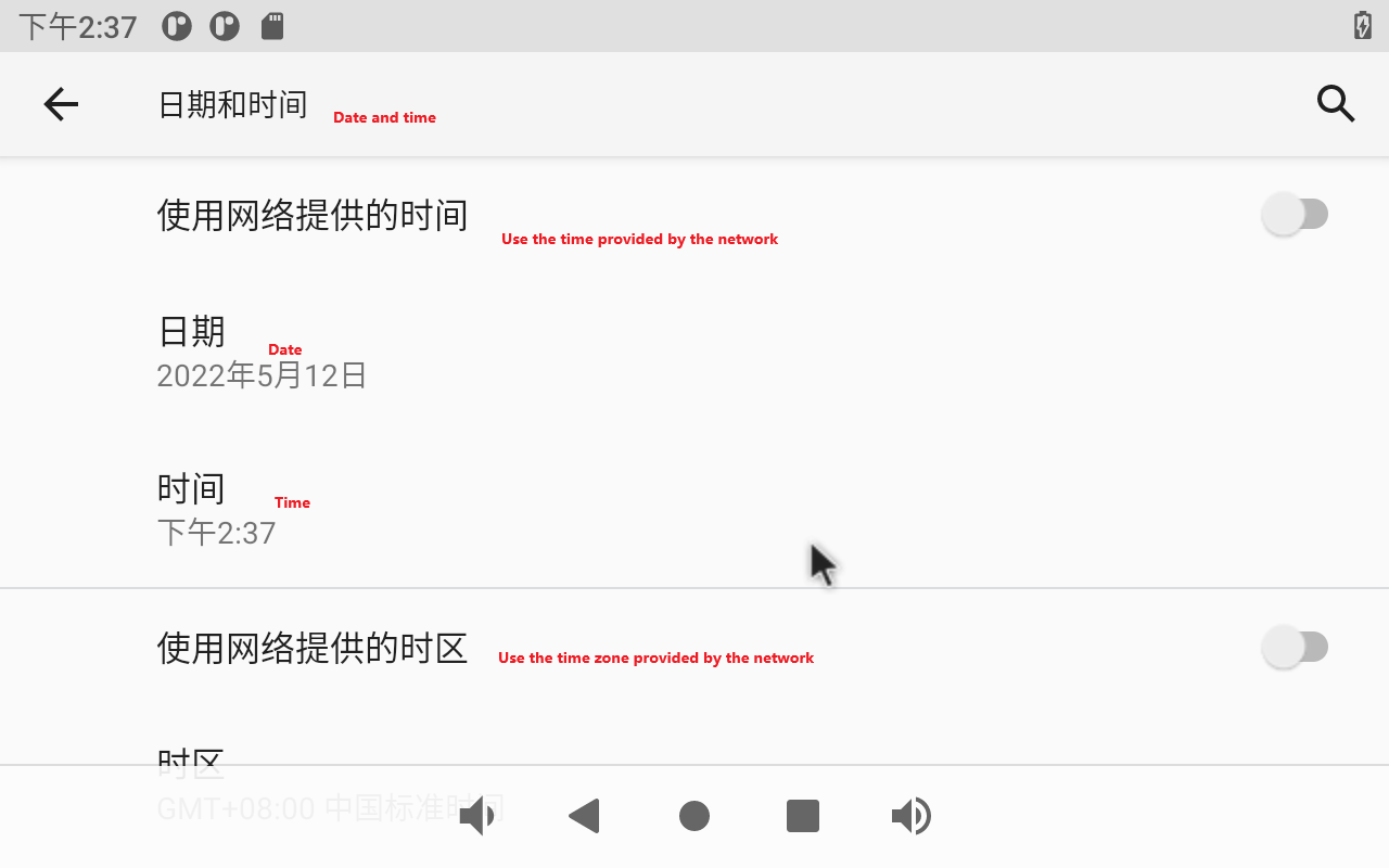
3.9 Time Settings(RTC)
Click “ ”, on the application interface to enter the setting interface:
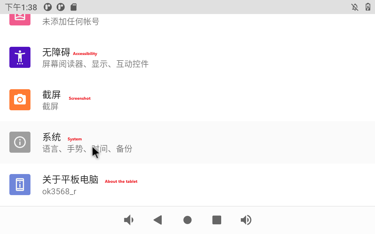
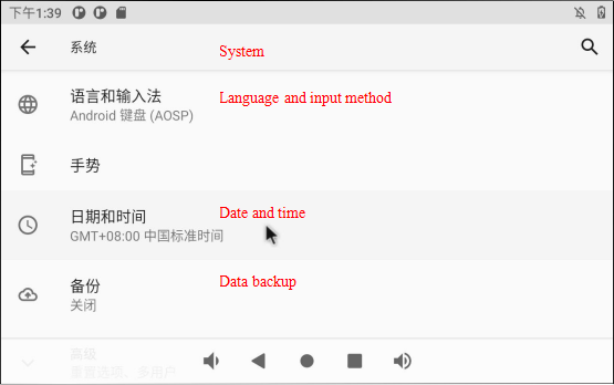
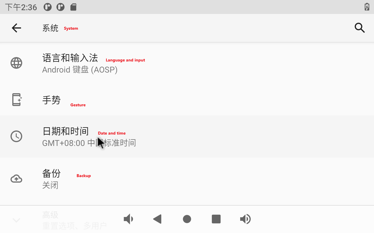
Select “System,” where you can change the date and time, and even after power failure, the time can still be synchronized (ensure that the button battery is installed on the board).
Turn off “Use Time From Network” to set the date and time separately.
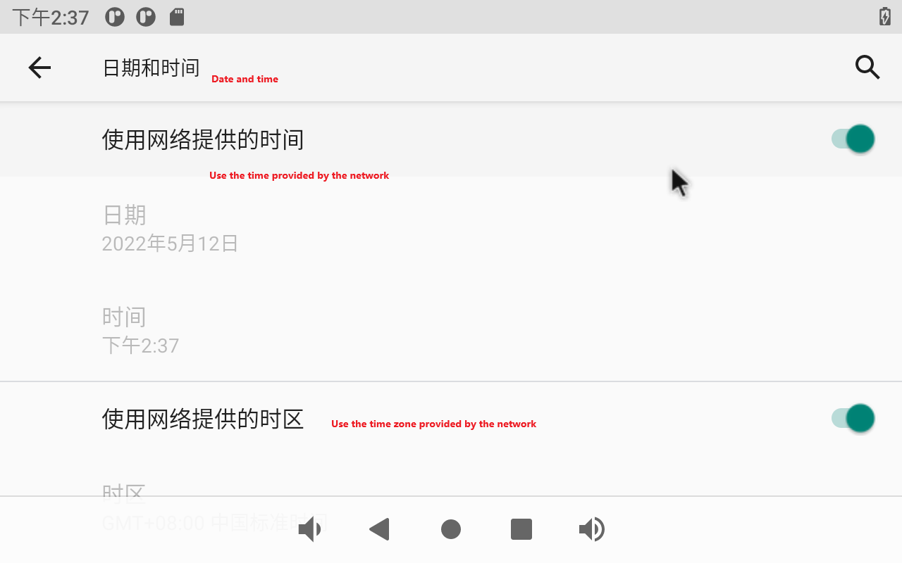
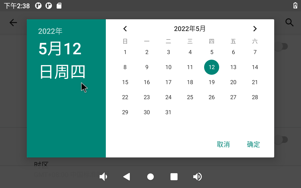
Click on “Set Date.”
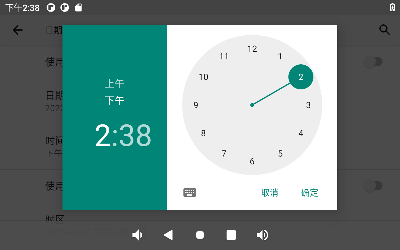
Click on “Set Time.”
3.10 Ethernet Test
Note:
When there are 4G and Ethernet at the same time, Ethernet is preferred by default; when there is 4G WiFi at the same time, WiFi is preferred by default. When both WiFi and Ethernet are present, Ethernet is prioritized by default.
1. Gigabit network port test:
Prepare a router and a network cable that can be connected to the external network port.
After inserting the network cable, click “ ” on the application interface:
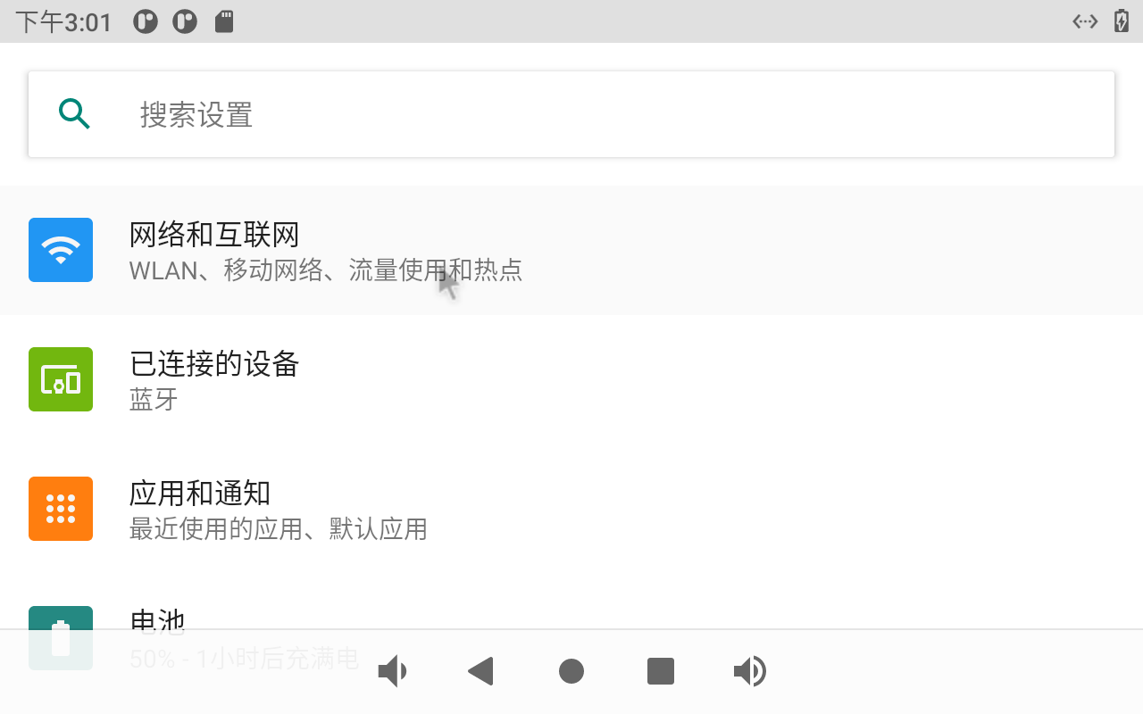
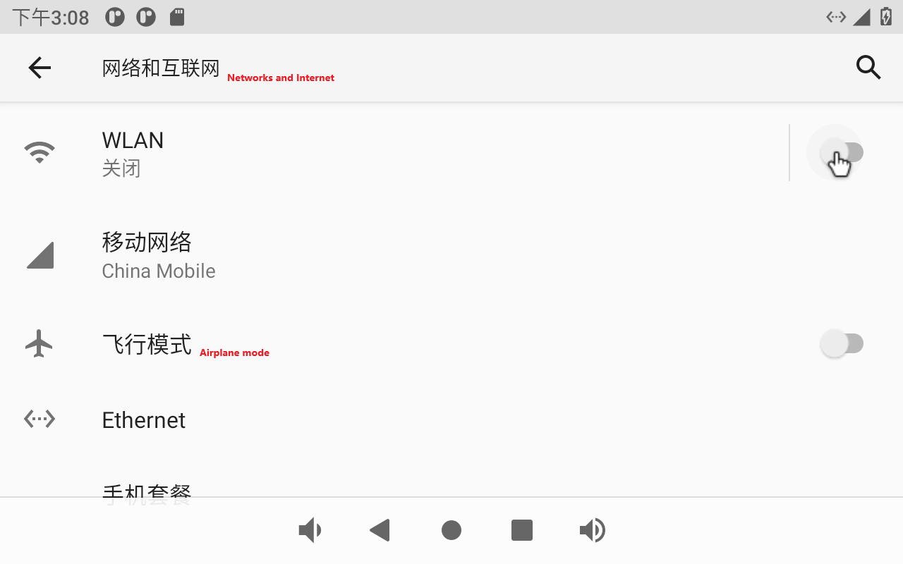
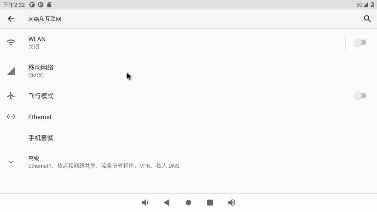
Click “Network and Internet”:
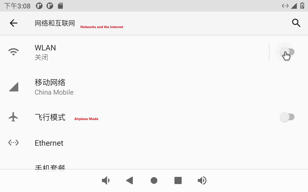
The OK3568 has 2 x Gigabit NIC on board (Ethernet ETH0 and Ethernet ETH1; the current interface settings only support ETH0). Click “Ethernet ETH0” to choose to automatically obtain IP DHCP or static IP. DHCP is recommended. If you set a static IP, make sure your network parameters are available.
Click “Ethernet”:
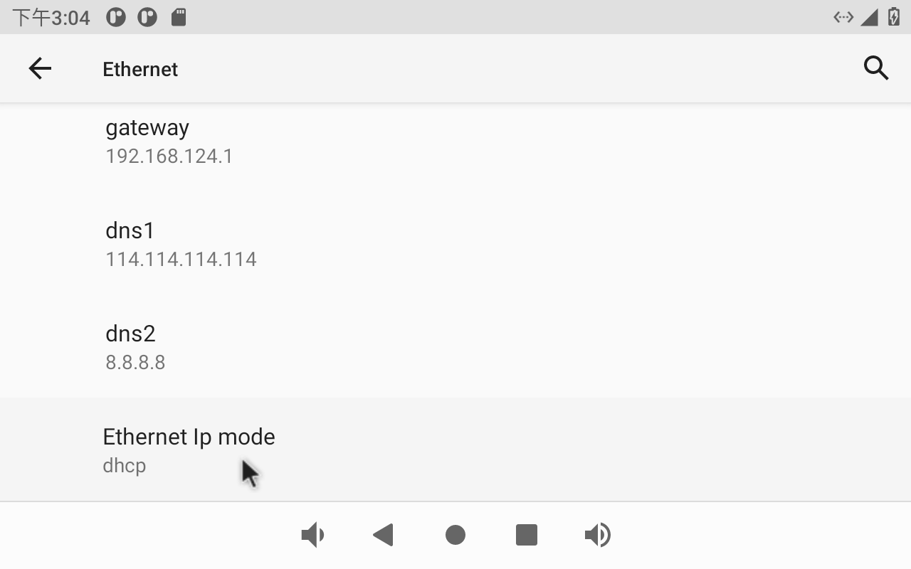
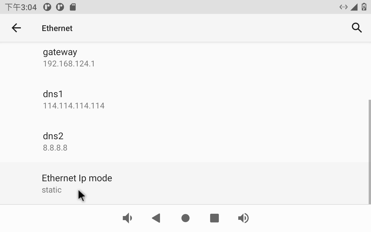
The default IP acquisition method is “dhcp”. If you want to set a static IP, click Ethernet Ip mode:
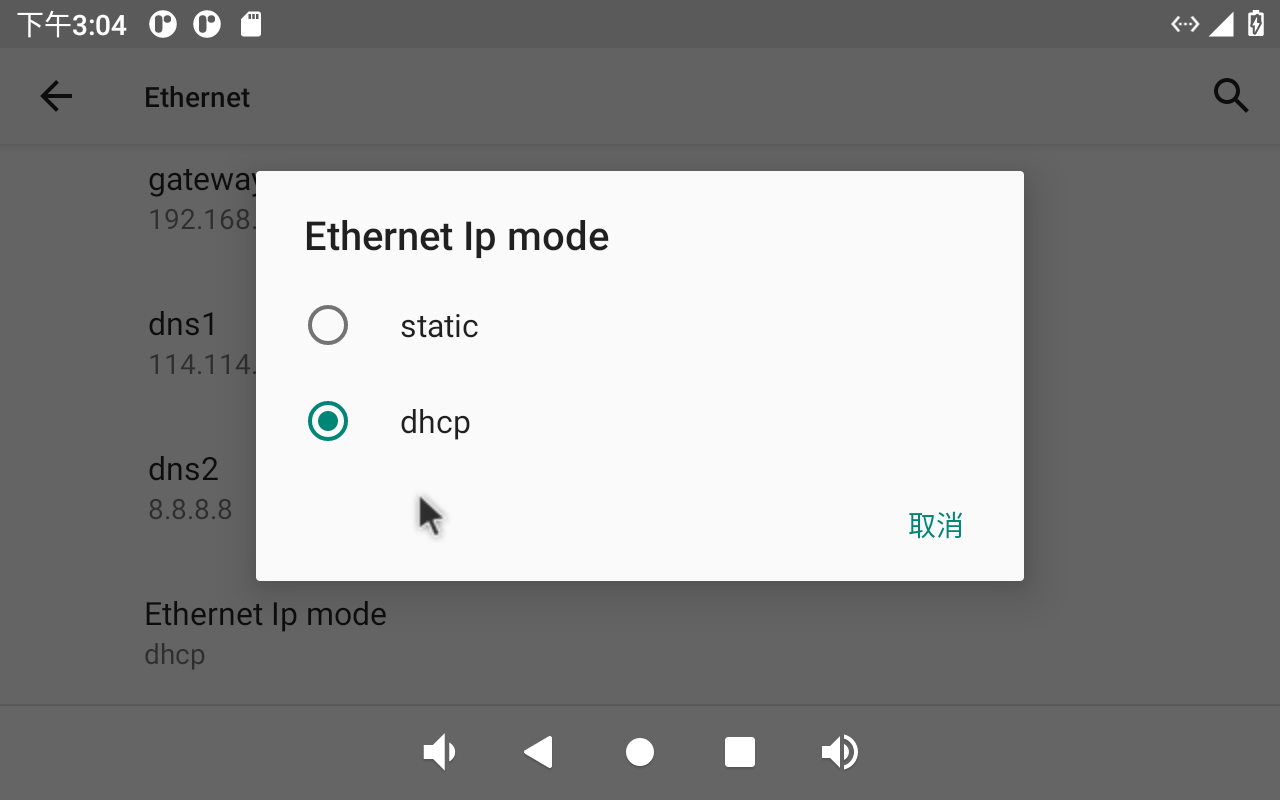
Select Static for static IP configuration:
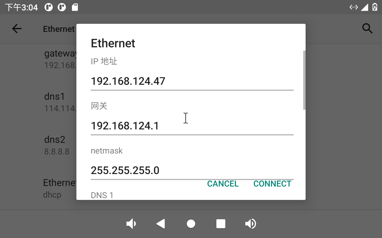
Click “CONNECT” to complete the configuration:
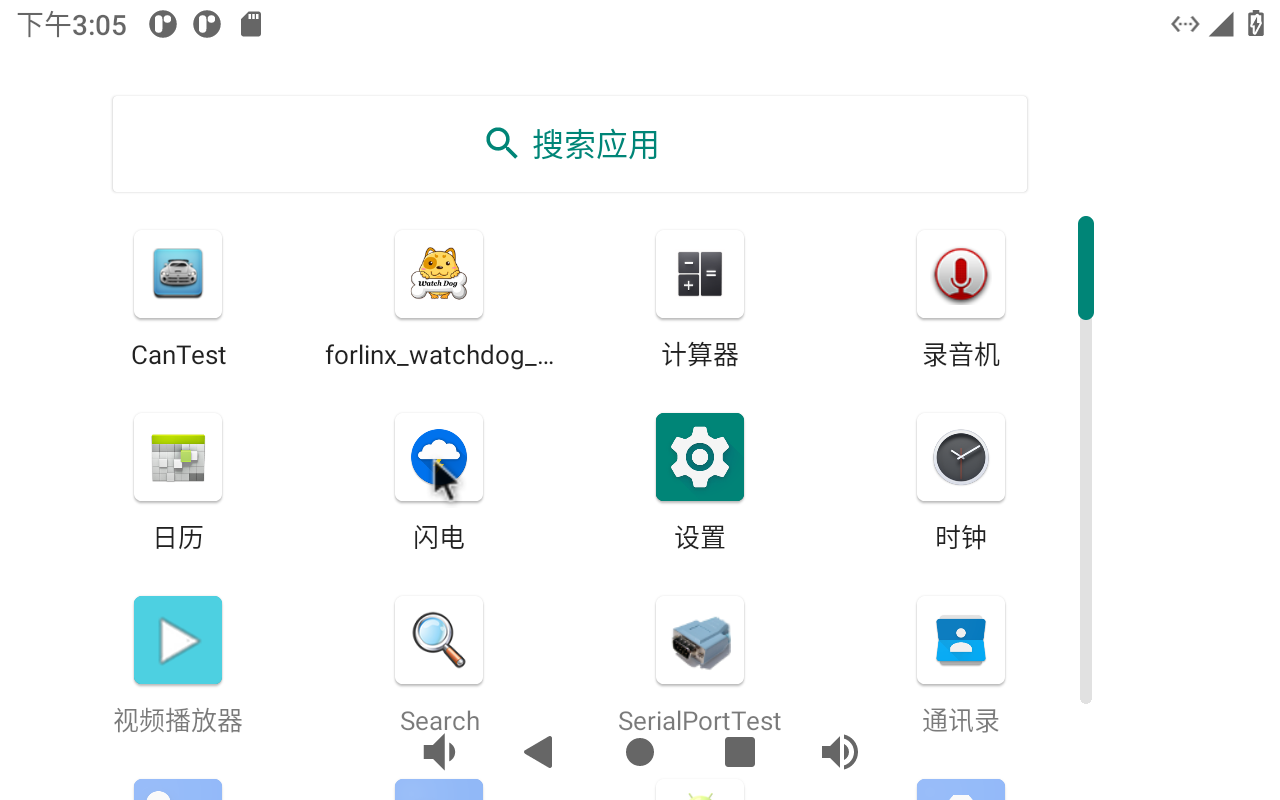
Click “Lightning” on the application interface for network test:
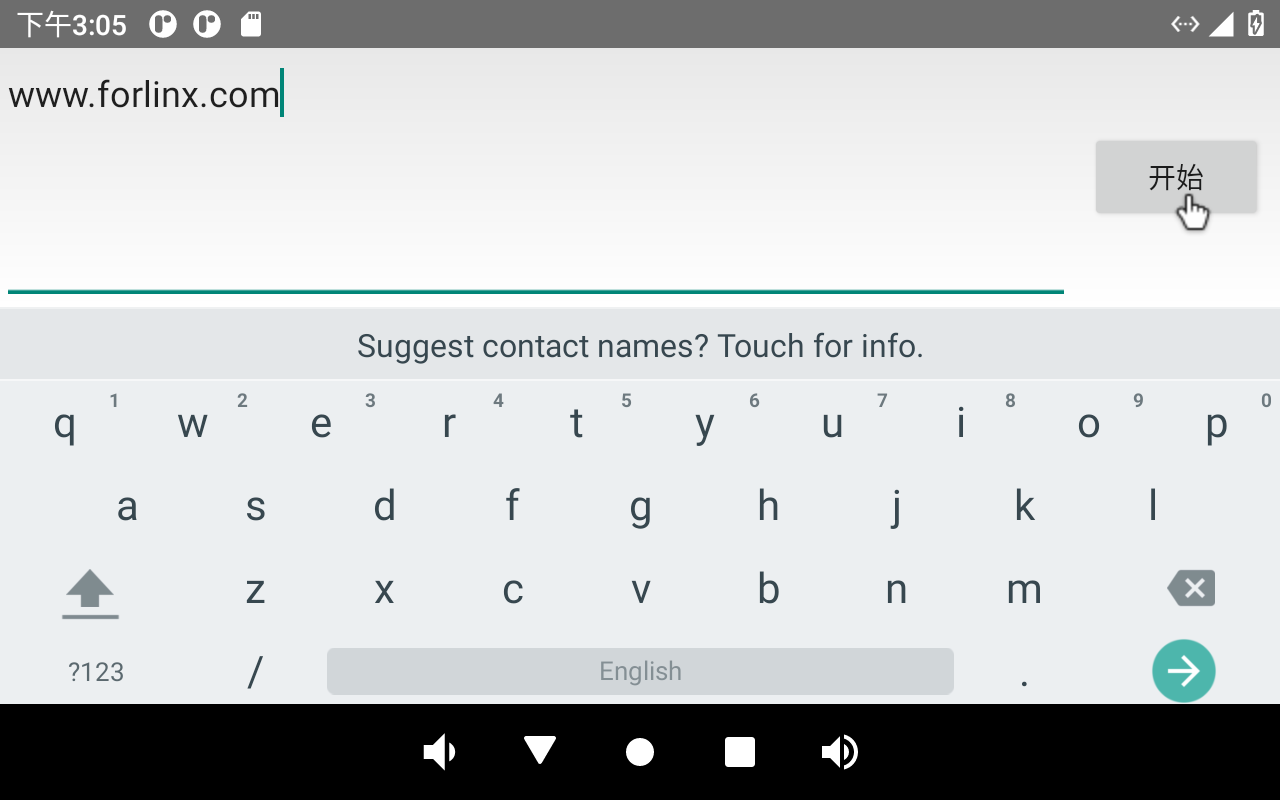
Enter “http://www.forlinx. net” in the domain name column and click “Start” to enter the official website of Forlinx.

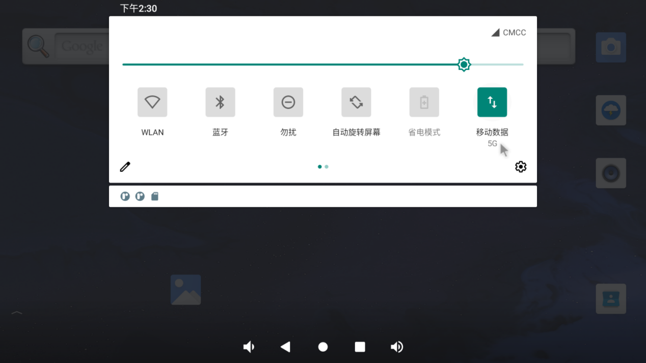
3.11 WiFi Internet
Note:
When 4G and Ethernet exist at the same time, Ethernet is preferred by default; When 4G WIFI exists at the same time, WIFI is preferred by default. When both WiFi and Ethernet are present, Ethernet is prioritized by default;
When testing WiFi, unplug the wired network;
Be sure to install the Wifi antenna when startup.
The OK3568 has an on-board AW-CM358SM module. Open settings, select “Network & Internet”, and click “WLAN”:
Click “Use WLAN”:
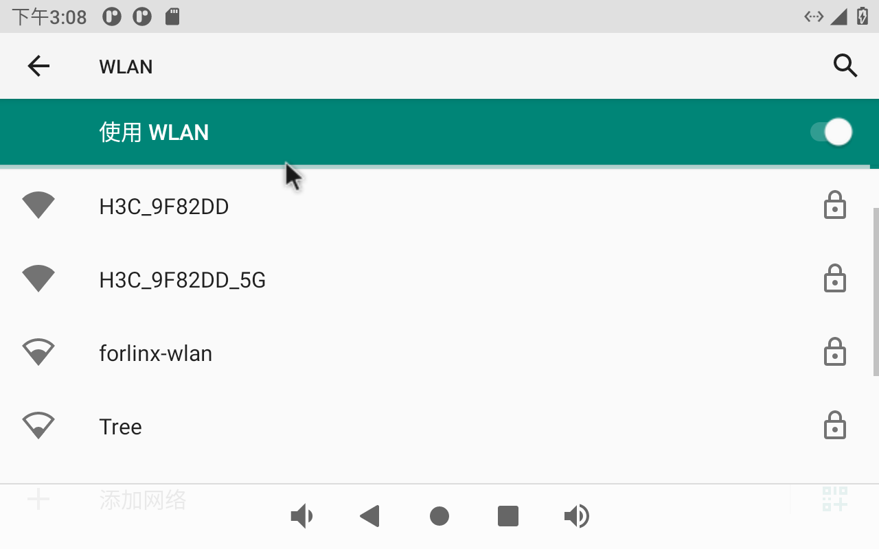
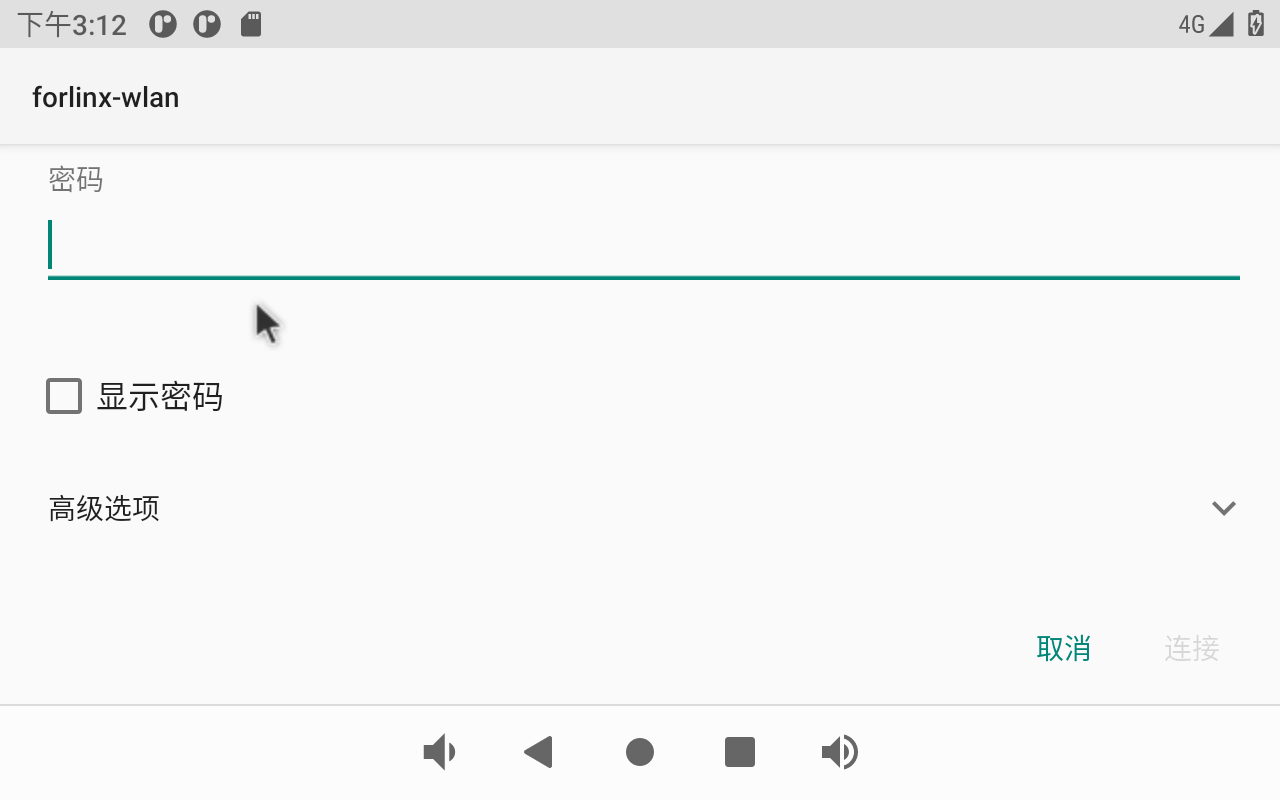
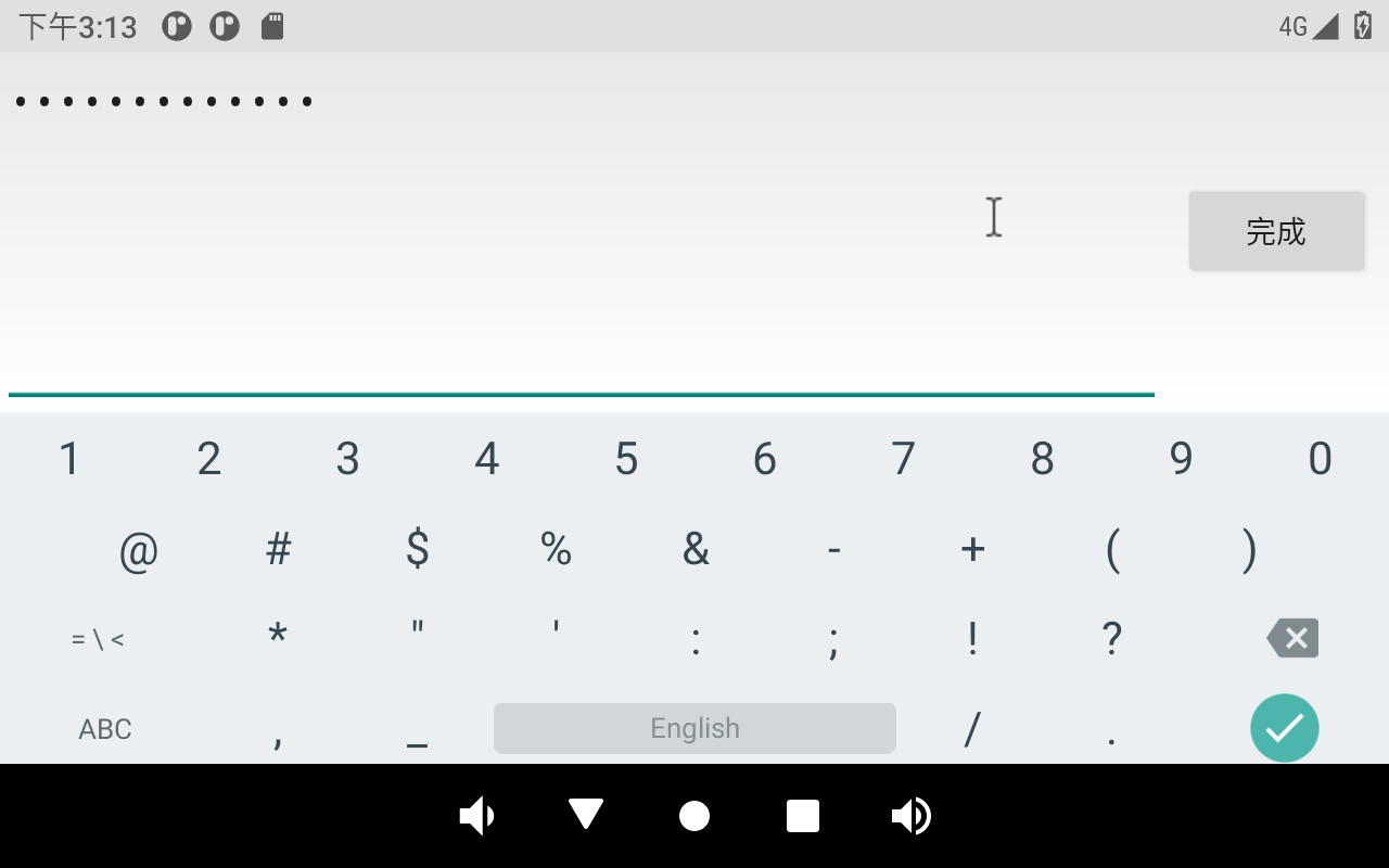
Click on the WIFI to be connected and enter the password:
After the connection is successful, you can open the Lightning Browser for network test:

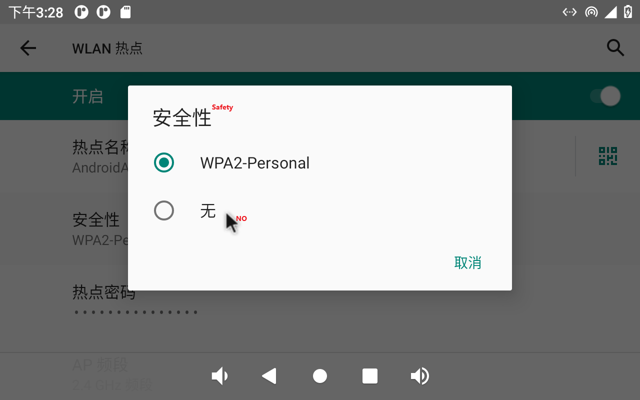
3.12 WiFi Hotspot Test
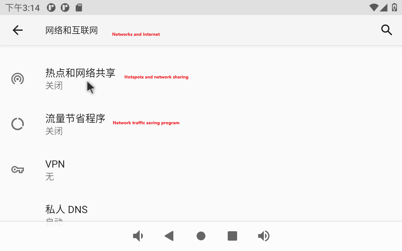
OK3568 supports the sharing of Ethernet or mobile networks through WIFI for WIFI hotspot testing. First, plug the network cable into the OK3568 ETH0 connector. Open Settings and click Network and Internet.
Click “Hotspot &tethering”:
Click “WLAN Hotspot”:
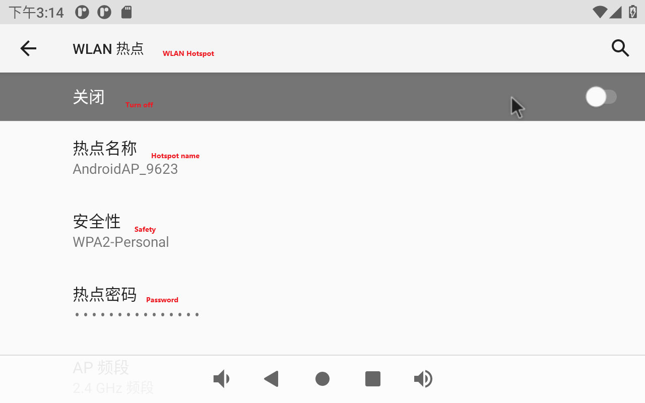
Enable the WLAN hotspot and set the hot spot name and password:
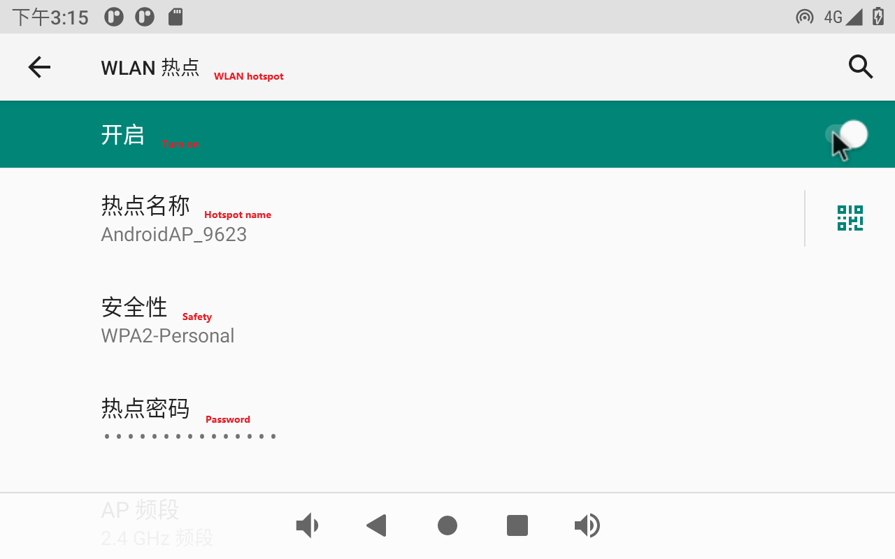
First set the hotspot name:
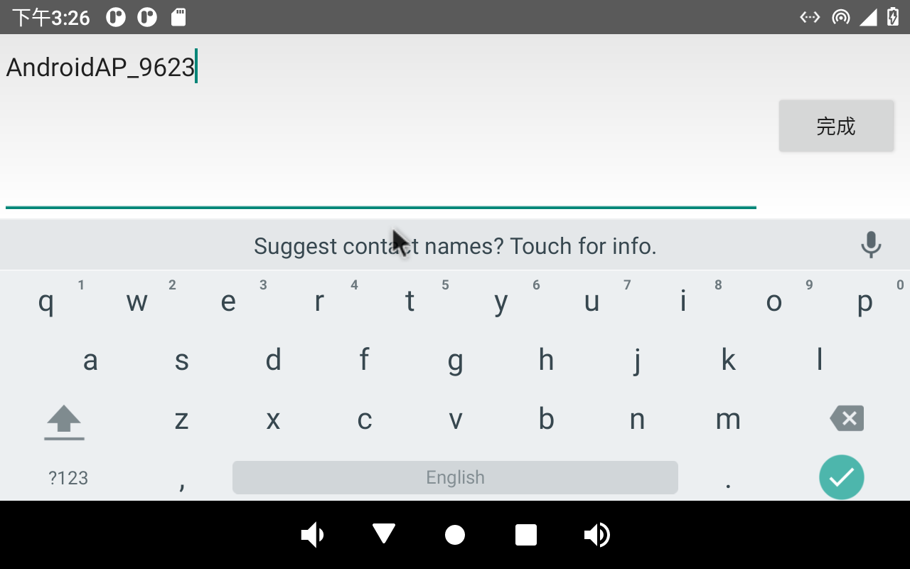
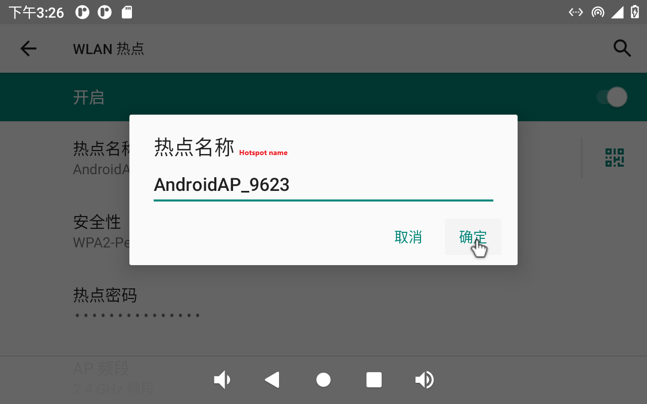
Click “Confirm”.
Set hotspot password:
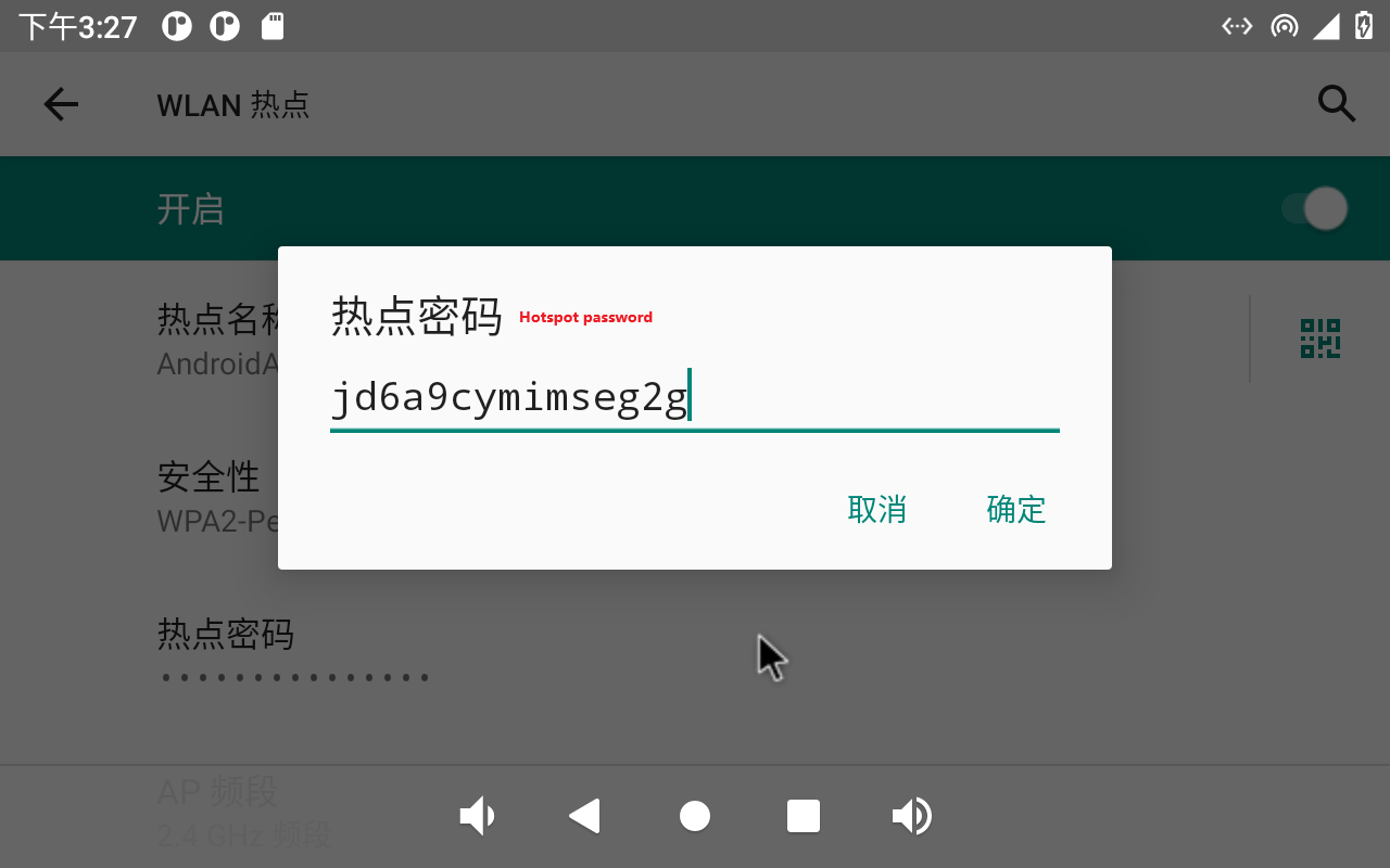
Click “Confirm”.
Set the AP band:
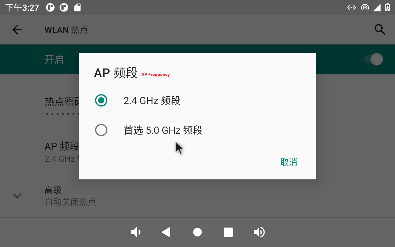
Click “Confirm”.
Set up security:
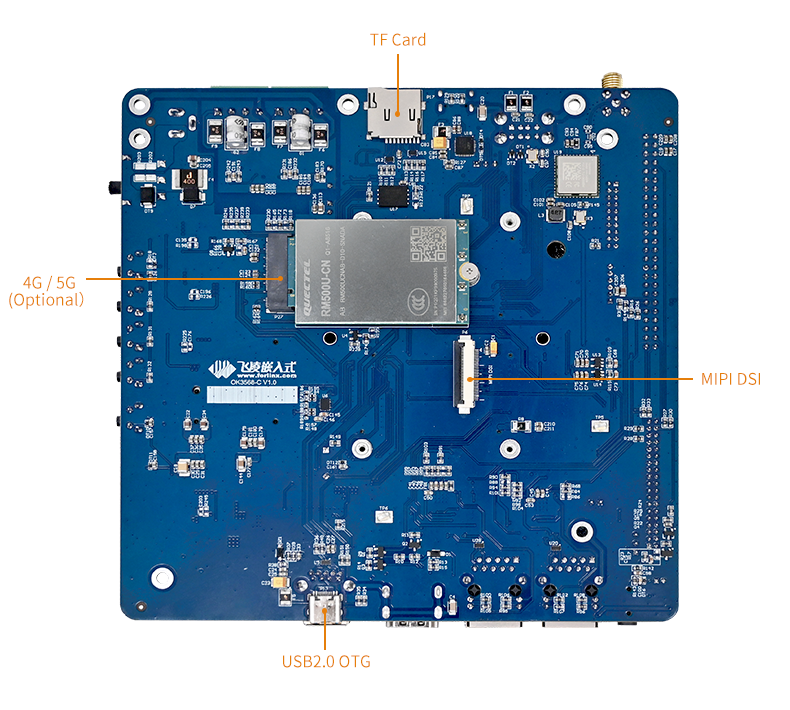
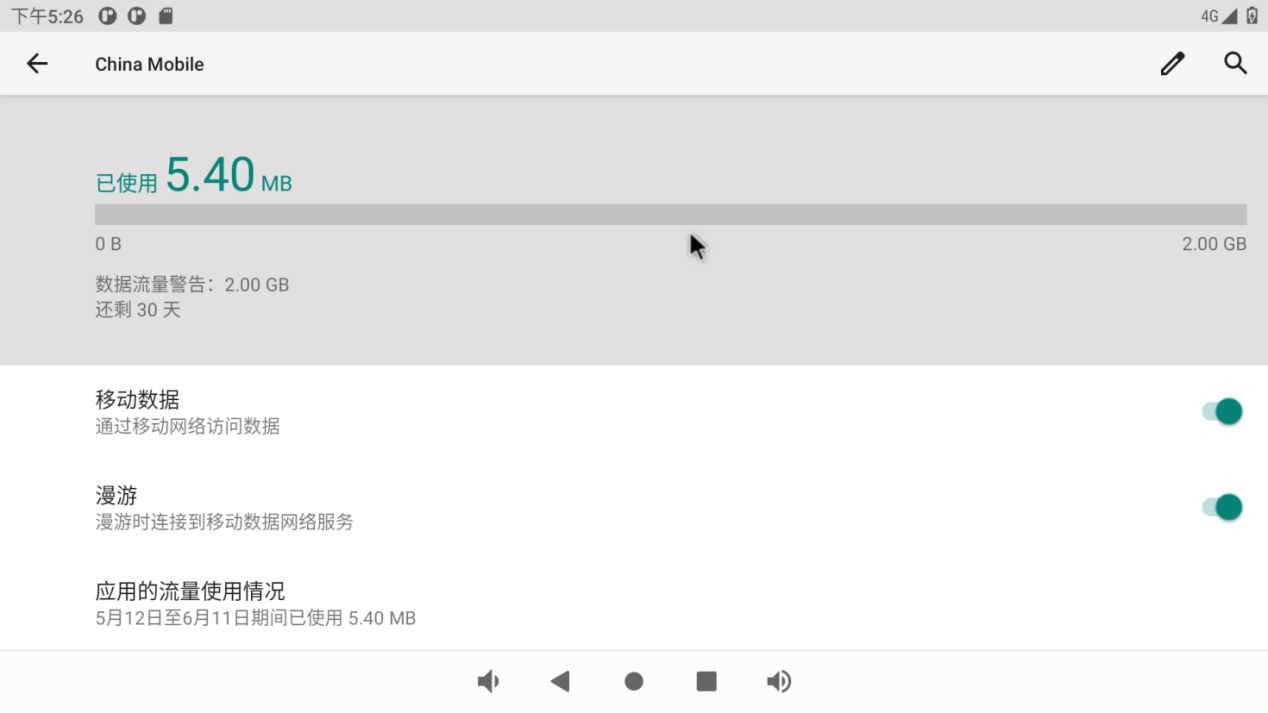
3.13 4G/5G Module Test
Note:
When There are 4G and Ethernet at the same time, Ethernet is preferred by default; when there is 4G WIFI at the same time, WIFI is preferred by default. When both WiFi and Ethernet are present, Ethernet is prioritized by default;
When testing 4G, unplug the wired network and turn off WiFi.
The OK3568 carrier board supports 4G modules (EM05) and 5G modules (RM500U). Before the test, please power off the development board, connect the 4G/5G module and insert the SIM card (pay attention to the direction of the SIM card), and start the development board.
Open Settings, select “Network and Internet”, and click “Mobile Network”:
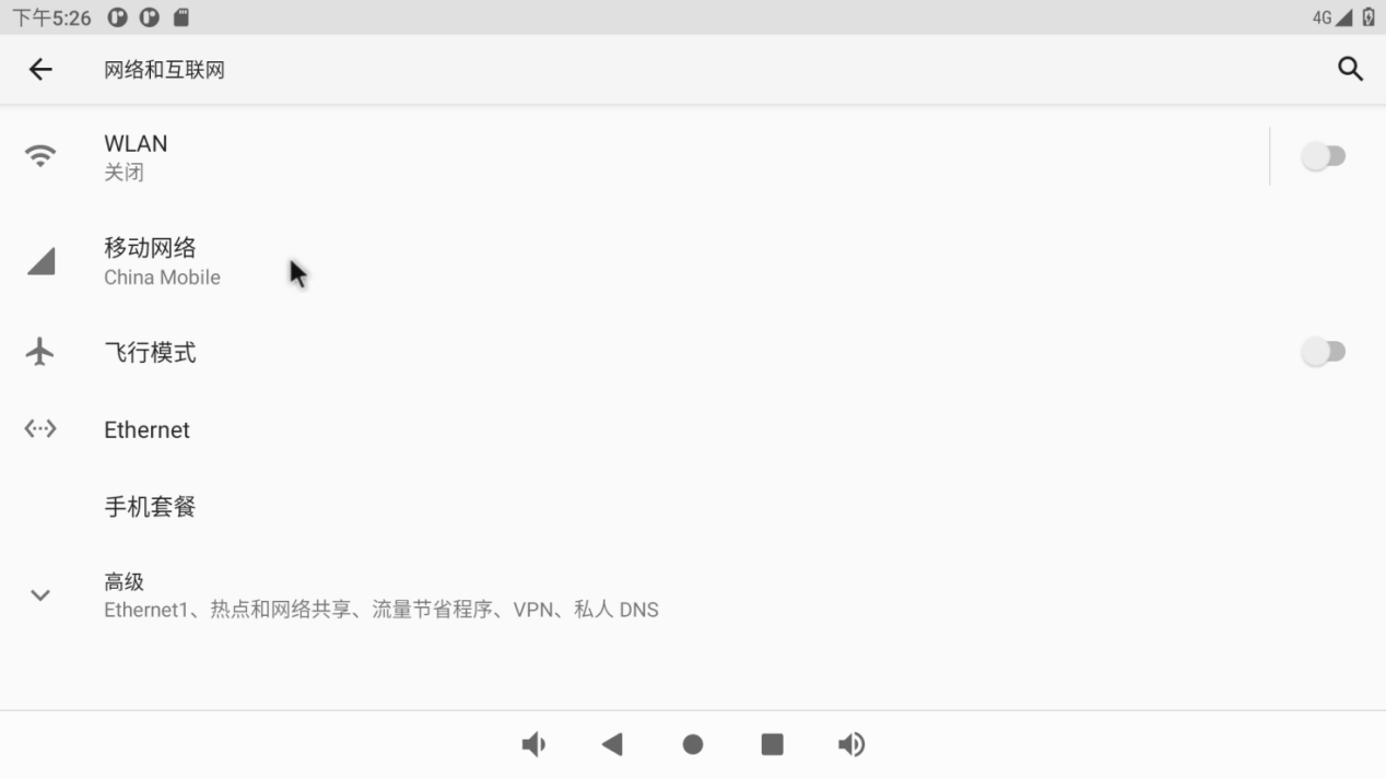
The default mobile network is on:
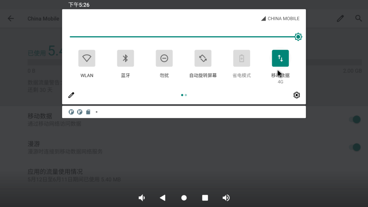
After the connection is successful, you can open the Lightning Browser for network test:
The test method of 5G is the same as that of 4G, and the difference is that the icon display is different:
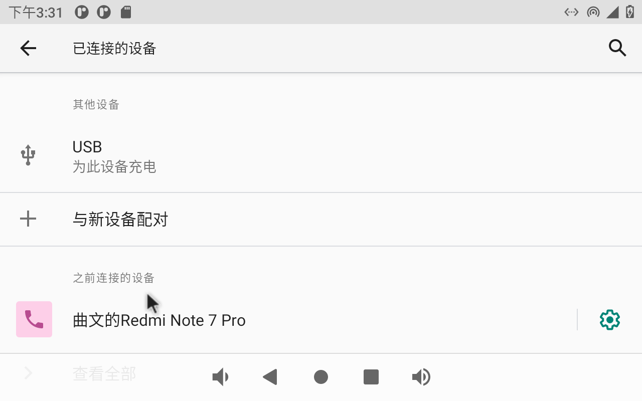
3.14 Bluetooth Test
Note: The current system does not support iPhone Bluetooth connection.
The Bluetooth function test of OK3568 platform uses the WiFi & Bluetooth integrated module, which supports the connection of Bluetooth devices as the main device to transmit/receive files.
The testing method is as follows:
Click “ ”, on the application interface to enter the setting interface:
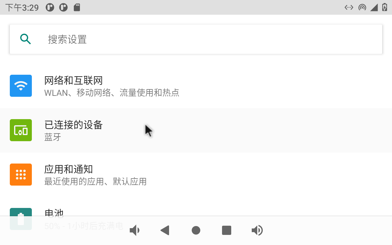
Click “Connected device” to enter the Bluetooth setting interface.
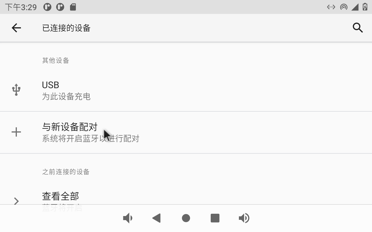
Click “+ pair with new device”, open PC Bluetooth to scan at the same time, and click the Bluetooth device to be connected.
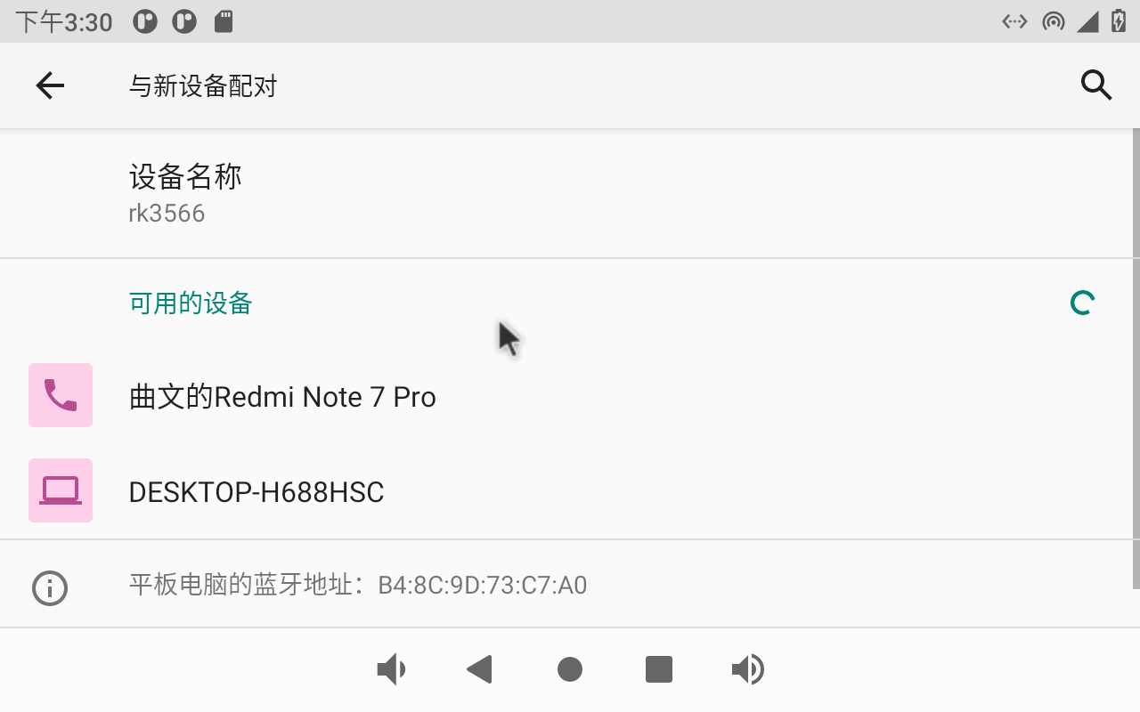
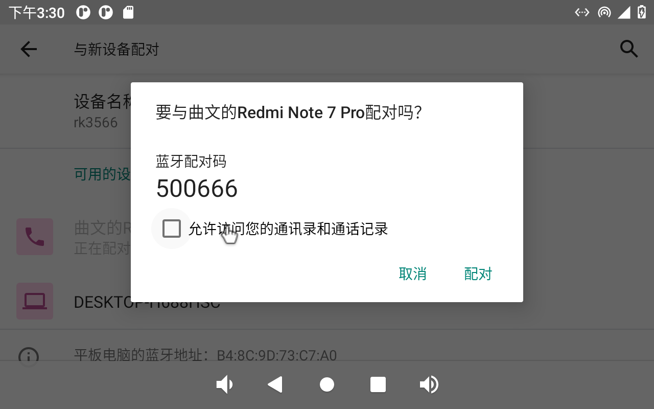
Click “Pairing”, the mobile phone performs the corresponding pairing operation, and the interface of successful Bluetooth connection displays:
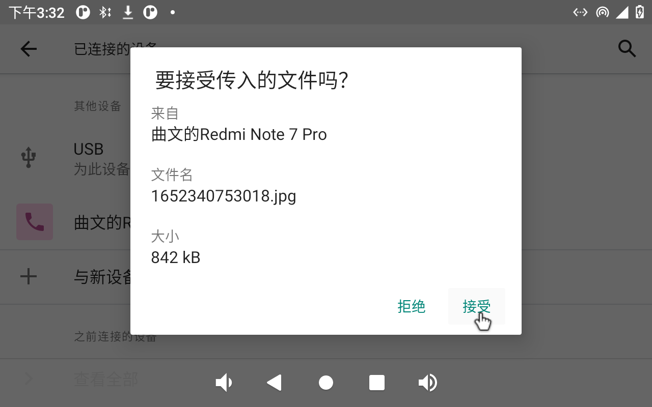
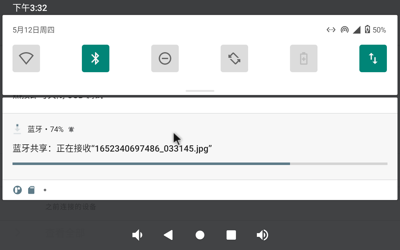
File transfer file test:
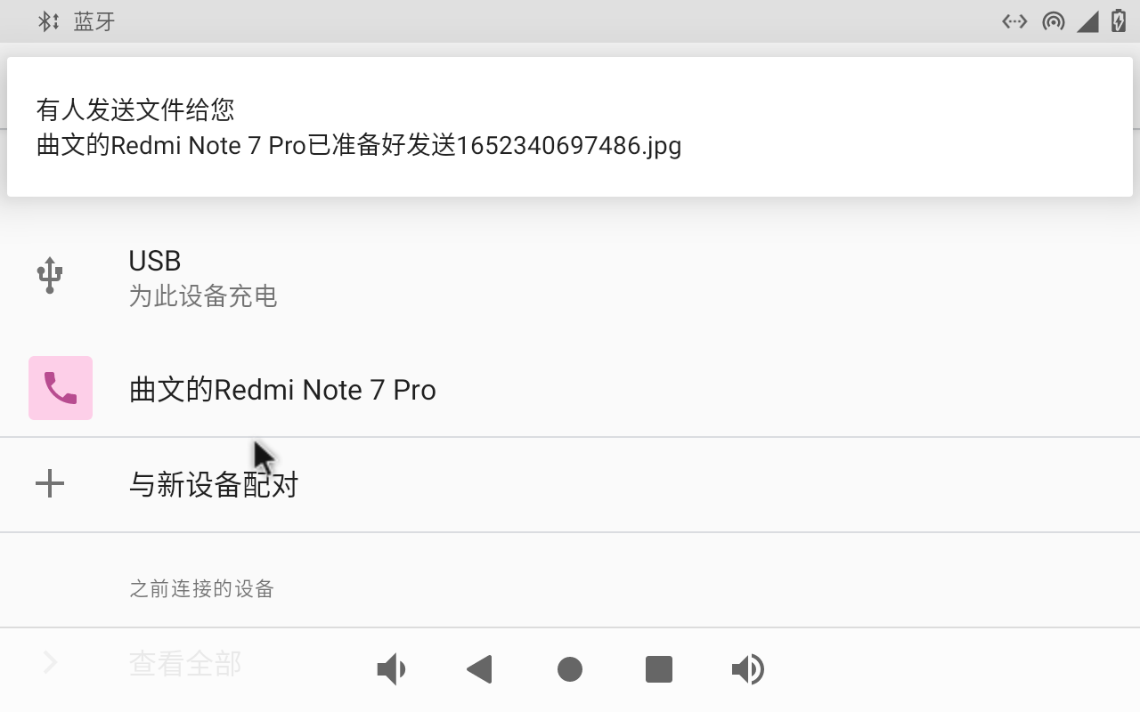
Select to accept the file:
3.15 Key Test (Sleep Wake-up)
There are 8 keys on the development board, including VOL +, VOL-, MENU, ESC, HOME, PWRON, RESET and Maskroom.
Key |
Function |
|---|---|
VOL+ |
VOL+ |
VOL- |
VOL- |
PWRON |
Wake up from sleep and power on/off |
Maskroom |
Work with RESET to enter maskrom mode. |
RESET |
RESET |
HOME |
Pop-up menu Home screen settings, Widget, Wallpaper |
ESC |
Return |
The default factory setting is the non-hibernation state. At this time, press the PWRON key lightly to turn off the screen and enter the hibernation state (note that the carrier board cannot be inserted into the wake-up source such as USB OTG).
Currently, CXMT memory products have removed the sleep/wake-up functionality. Please verify and confirm the configuration of the SoM.
The sleep printing information is as follows:
[ 7289.309434] OOM killer disabled.
[ 7289.309445] Freezing remaining freezable tasks ... (elapsed 0.003 seconds) done.
[ 7289.312662] Suspending console(s) (use no_console_suspend to debug)
abcdeghINFO:    sleep mode config[0x5ec]:
INFO:           mode: RKPM_SLP_CENTER_PD
INFO:           mode: RKPM_SLP_ARMOFF_LOGOFF
INFO:           mode: RKPM_SLP_PMIC_LP
INFO:           mode: RKPM_SLP_HW_PLLS_PD
INFO:           mode: RKPM_SLP_PMUALIVE_32K
INFO:           mode: RKPM_SLP_OSC_DIS
INFO:           mode: RKPM_SLP_32K_PVTM
INFO:    wakeup source config[0x10]:
INFO:           Enable GPIO0 interrupt as wakeup source
ijsramwf
In the sleep state, press the PWRON key again to wake up the CPU.
Note: The mipi screen does not support sleep and wakeup.
Press and hold PWRON for “Shutdown” and “Restart”.
The other buttons have simpler functions, so please test them yourself.
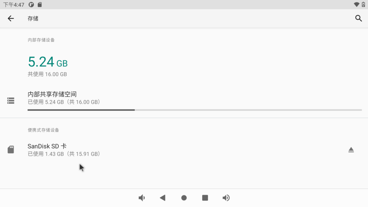
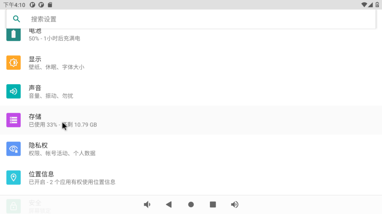
3.16 TF Card and USB Storage Test
It is a test of TF card and USB storage device. Insert the USB device into the OK3568 USB Host port. The system will automatically detect the insertion of the USB flash drive.
Click “ ”, on the application interface to enter the setting interface:
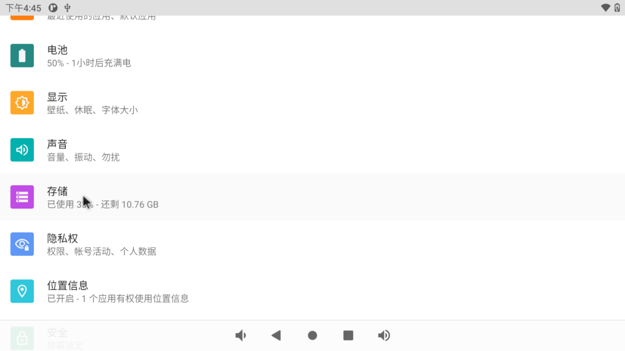
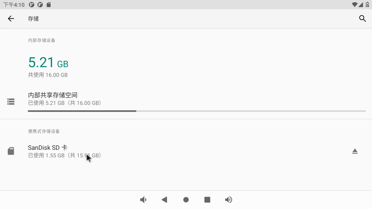
Click “Storage” to view the internal storage device and the inserted U disk device:
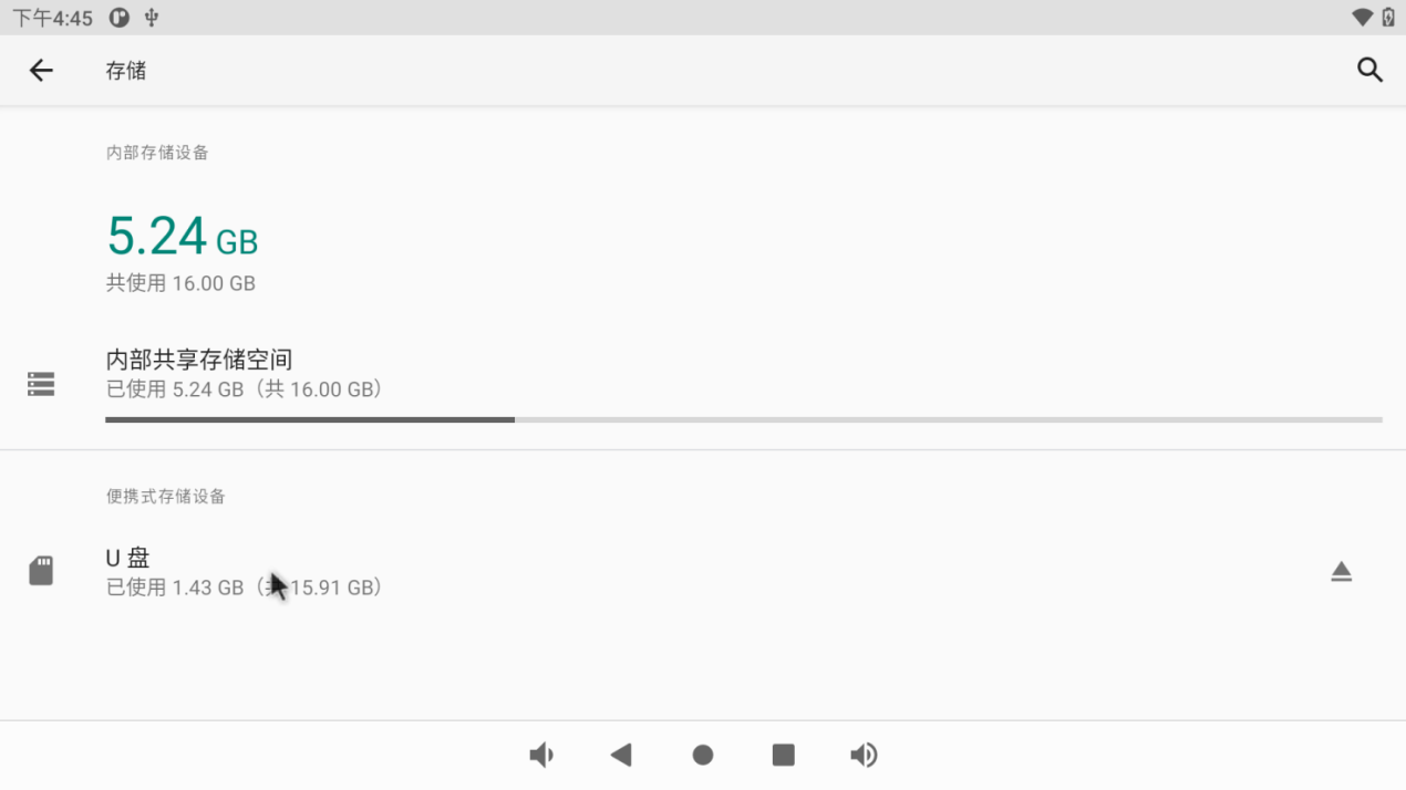
Click the USB flash disk to view the contents of the USB flash disk for reading and writing:
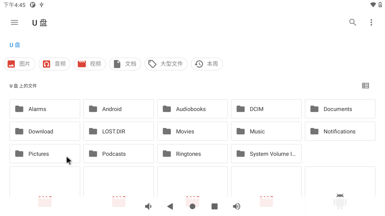
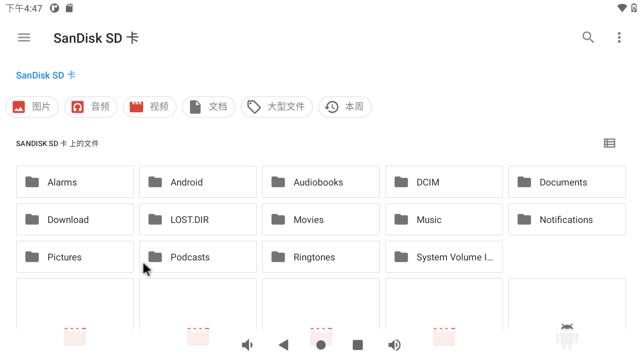
The TF card reading and writing method is the same as the U disk reading and writing test method. Insert the TF card into the TF card slot, and the system will automatically detect the insertion of the TF card. You can also view the contents of the TF card in the storage interface:
3.17 USB Mouse Test
Once the system is running, you can plug in a USB mouse into the USB host. You will then see the mouse cursor “ ”, within the interface, and you can navigate and operate the Android system using the mouse.
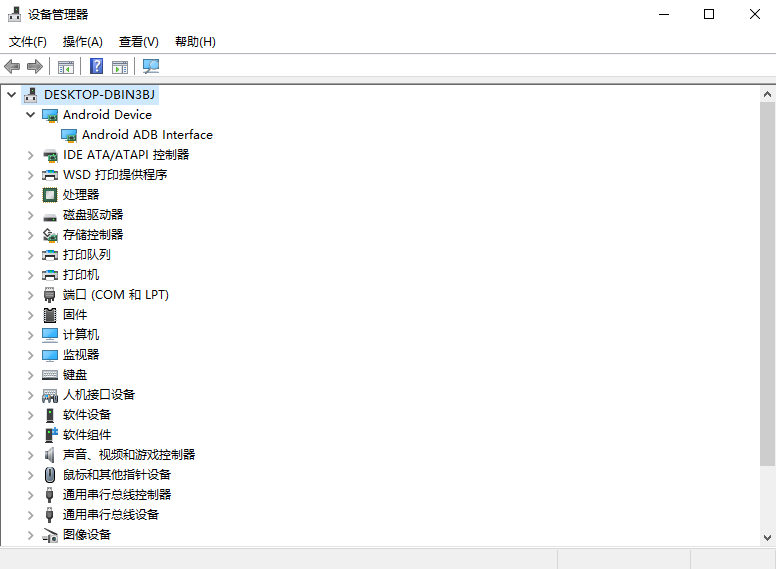
3.18 USB OTG Interface Test
The OK3568 development board supports USB OTG functionality.
Connect the computer through the otg cable, and the computer will recognize the board as follows:
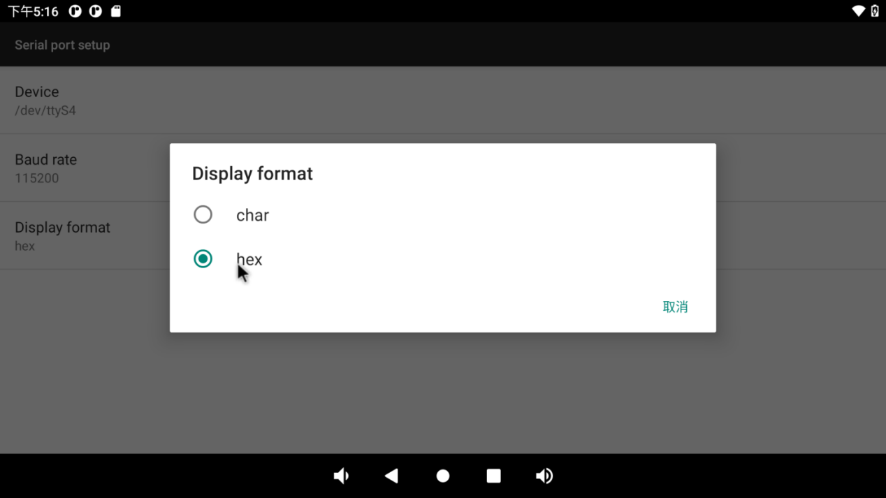
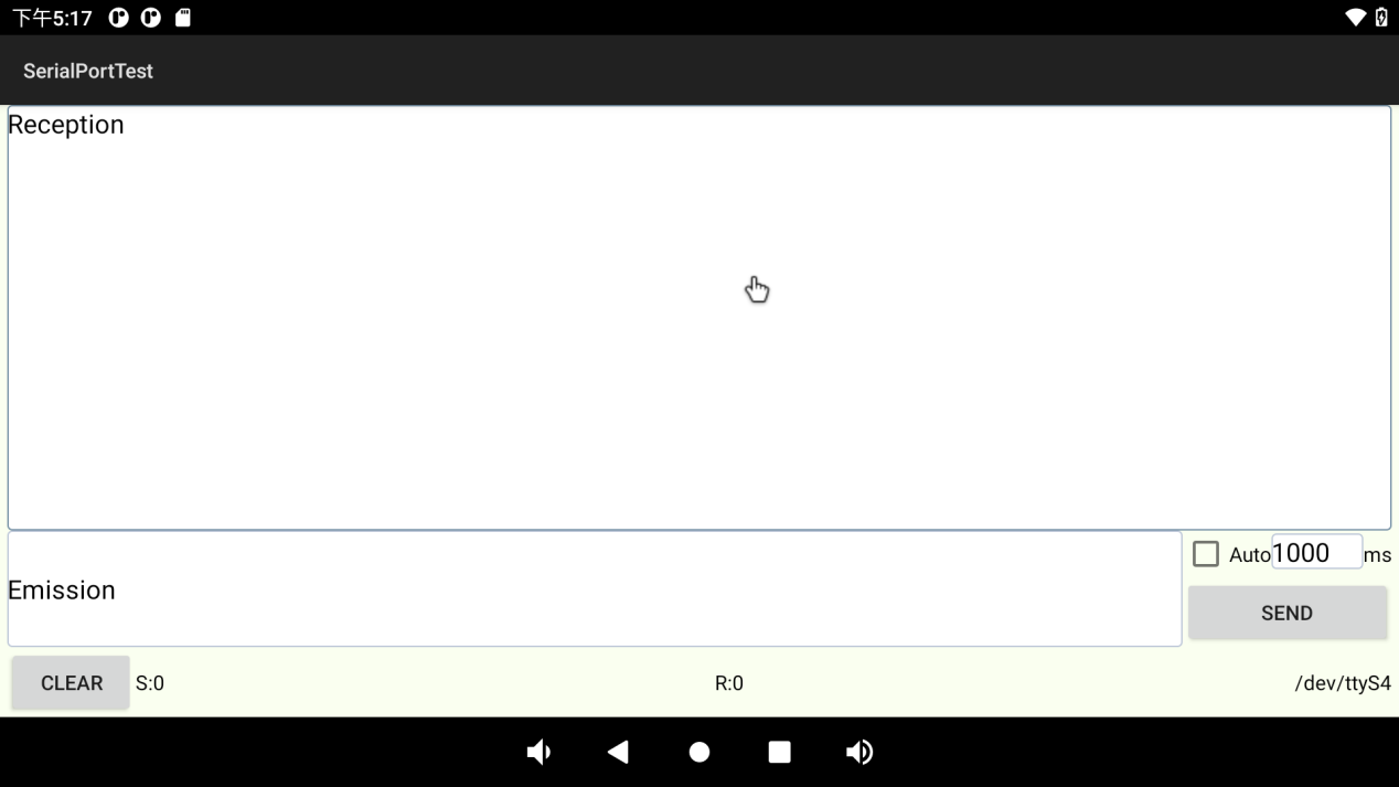
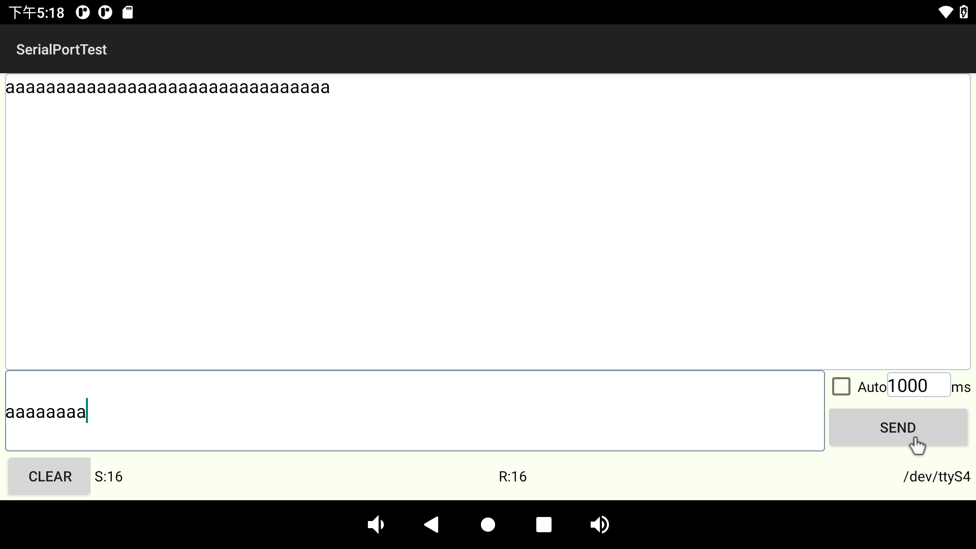
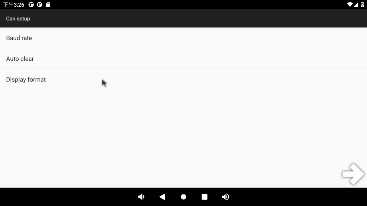
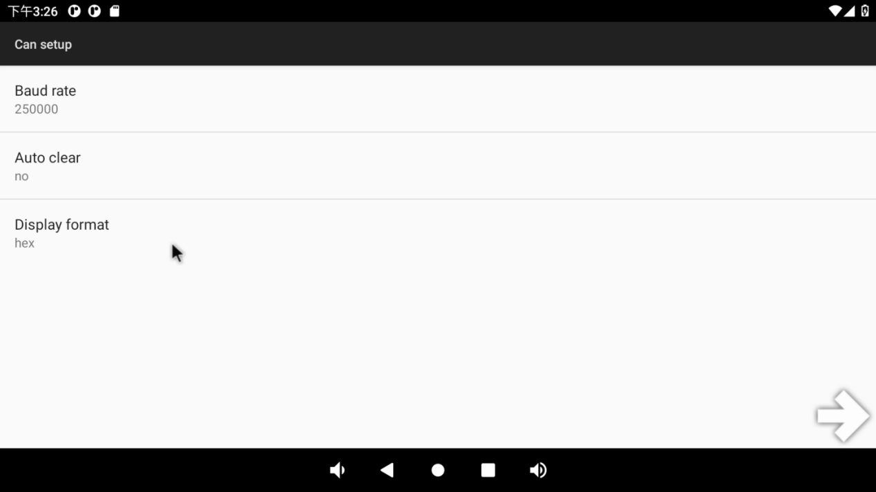
3.19 Serial Port Test
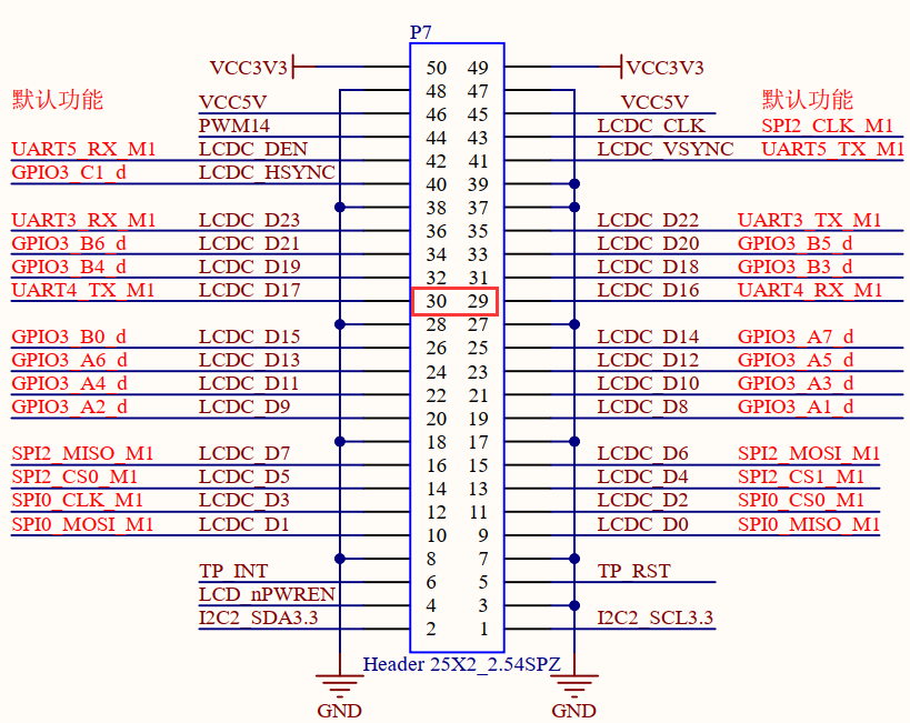
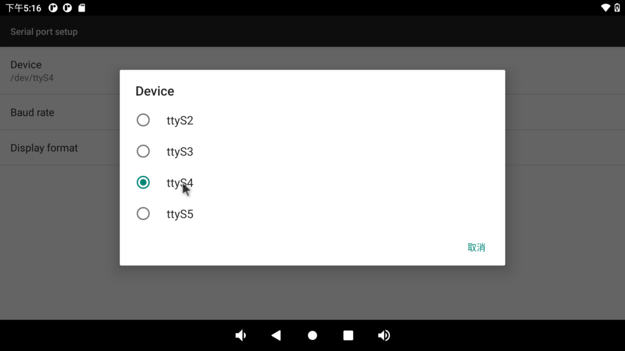
UART3, UART4, UART5 and UART8 serial ports are indicated in the schematic diagram of OK3568 platform carrier board, in which UART2 is the debugging serial port and UART8 is the Bluetooth serial port. The default device names of UART3, UART4 and UART5 in the development board are ttyS3, ttyS4 and ttyS5 respectively. Here, take the test of UART4 serial port as an example. According to the schematic diagram of the development board, the transceiver pins of UART4 are short-circuited, corresponding to PIN29 and PIN30 respectively.
Open the serial port test program on the desktop .
.
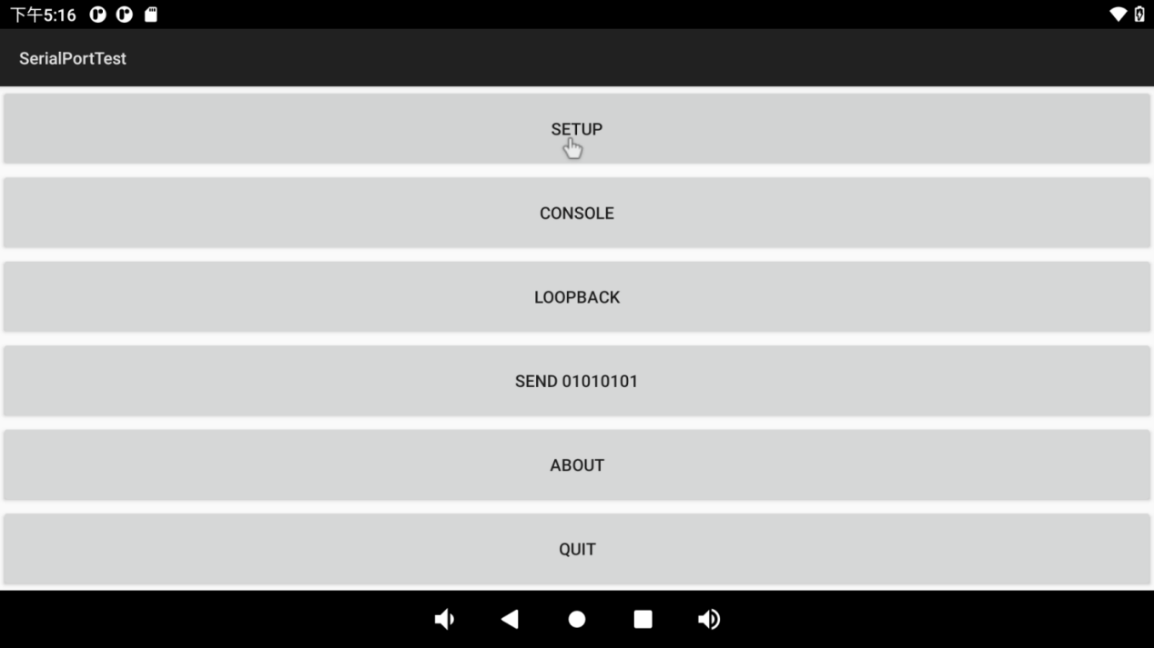
Click the “SETUP” button:
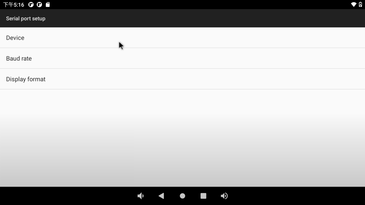
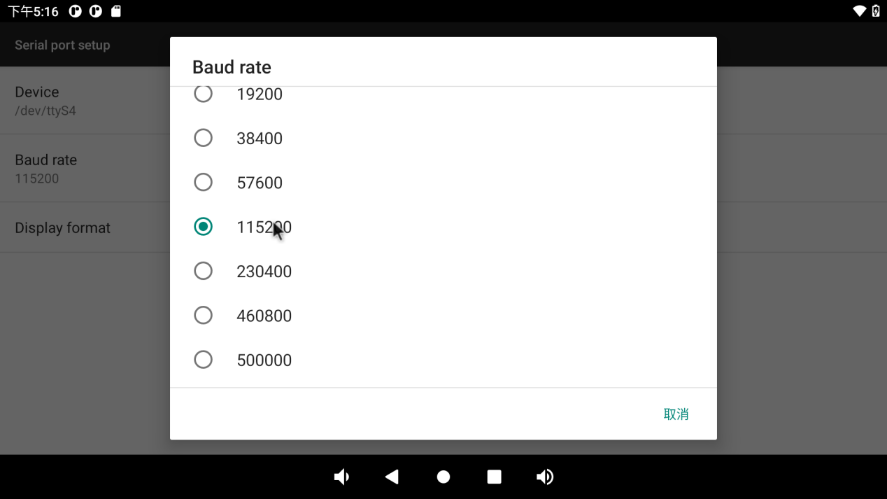
Set serial port device, baud rate and display format:
Then click the “Loopback” option in the previous menu to perform the loopback test.
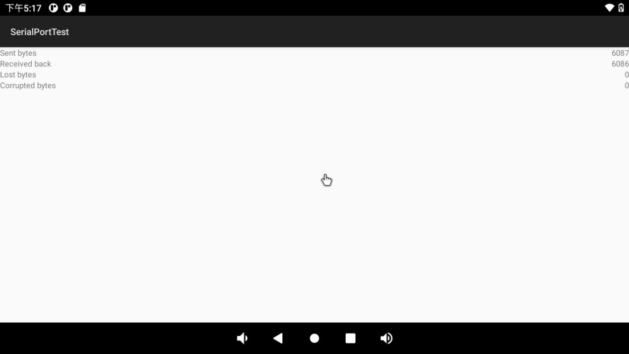
Click the “CONSOLE” option in the previous menu to perform the send-receive test:
3.20 CAN Test
OK3568-C/OK3568-C2 platform has two CAN bus interfaces, CAN0 and CAN1. CAN connection mode: Connection of the H terminal of CAN to other CAN devices; connection of the L terminal of CAN to other CAN devices.
Connect CAN0 and CAN1, execute the following command at the development board terminal, and open the can1 interface:
console:/ $ su
console:/ # ifconfig can1 down
console:/ # ip link set can1 up type can bitrate 250000
console:/ # ifconfig can1 up
console:/ # candump can1
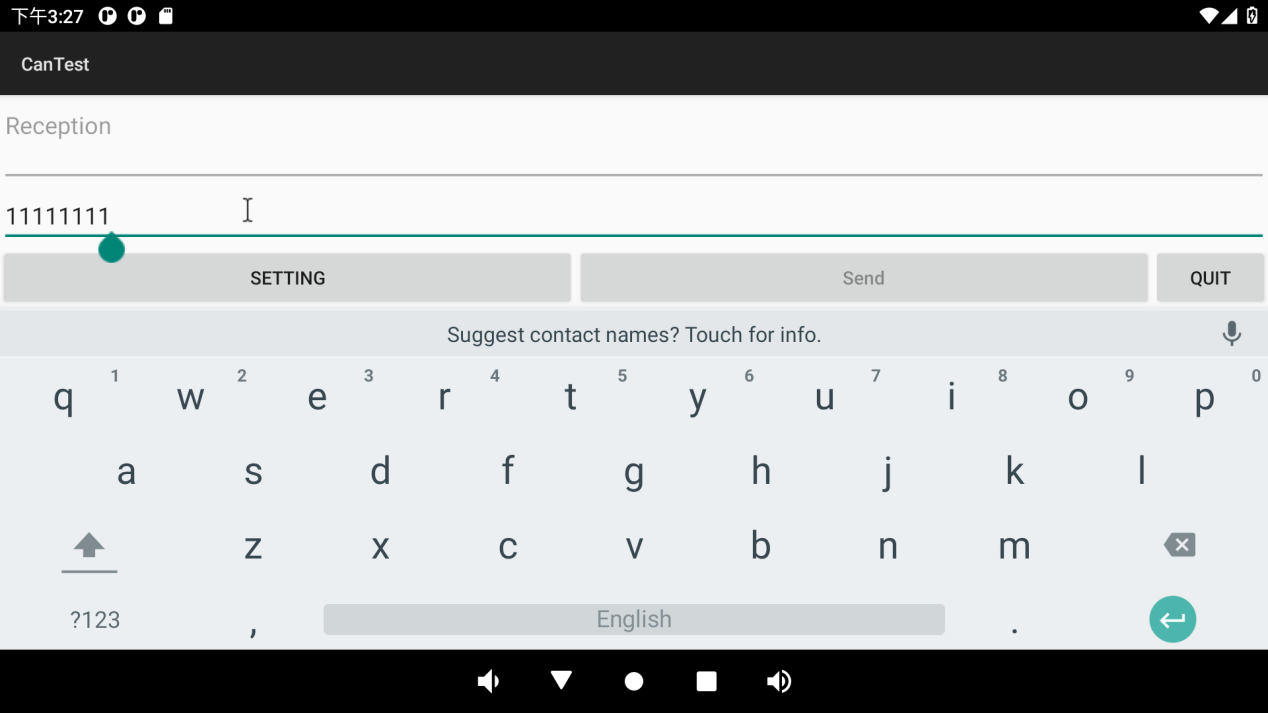
Open “ ”APP and configure CAN0 interface (APP only supports configuration of CAN0 interface temporarily):
 Click “SETTING” to configure the same baud rate as CAN1:
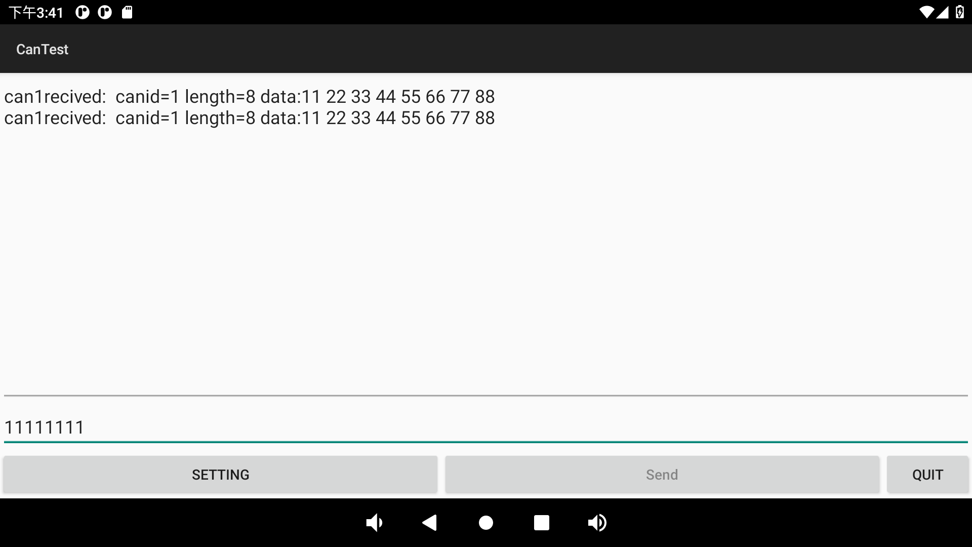
Click “ ” to return to the transceiver interface, and conduct the transceiver test with CAN1 (CAN1 uses the serial port terminal):
CAN1 executes the send command:
console:/ # cansend can1 -i 0x123 0x11 0x22 0x33 0x44 0x55 0x66 0x77 0x88     //Send standard frame
interface = can1, family = 29, type = 3, proto = 1

console:/ # cansend can1 -i 0x123 -e 0x11 0x22 0x33 0x44 0x55 0x66 0x77 0x88     //Send extended frame
interface = can1, family = 29, type = 3, proto = 1
APP receives the message sent by CAN1:
CAN1 receives the message sent by CAN0 using the candump instruction:
console:/ # candump can1&
[1] 2078
console:/ # interface = can1, family = 29, type = 3, proto = 1
[  546.790013] healthd: battery l=50 v=3 t=2.6 h=2 st=3 fc=100 chg=au

console:/ # <0x123> [4] 11 11 11 11
<0x123> [4] 11 11 11 11
<0x123> [4] 11 11 11 11
<0x123> [4] 11 11 11 11
3.21 Watchdog Test
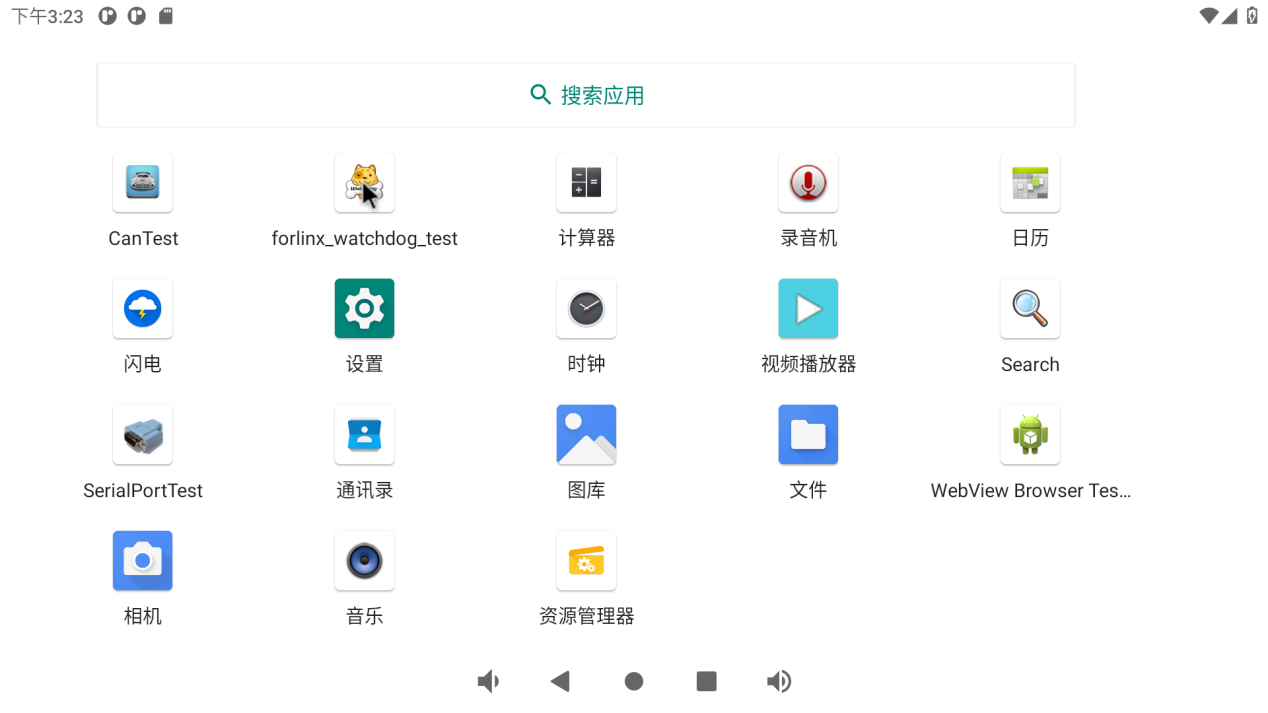
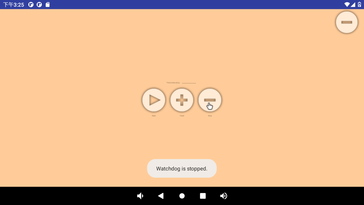
Click “forlinux _ watchdog _ test” “on the application interface to enter the watchdog test:
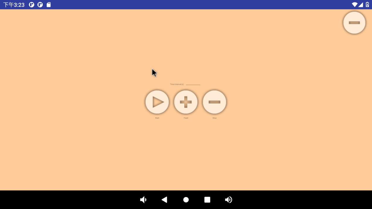
There are three buttons on the interface: “start”, “feed” and “stop”. Click “start” to see the dog and “feed” to feed the dog:
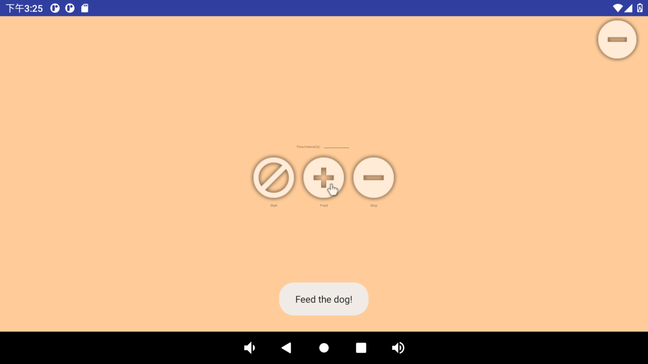
If a timeout (timeout of 10S) is not performed to feed the dog, the system reboots. Click “stop” to stop the watchdog test:
3.22 Camera Test
3.22.1 UVC Camera Test
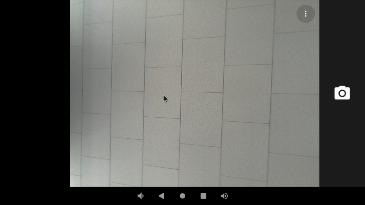
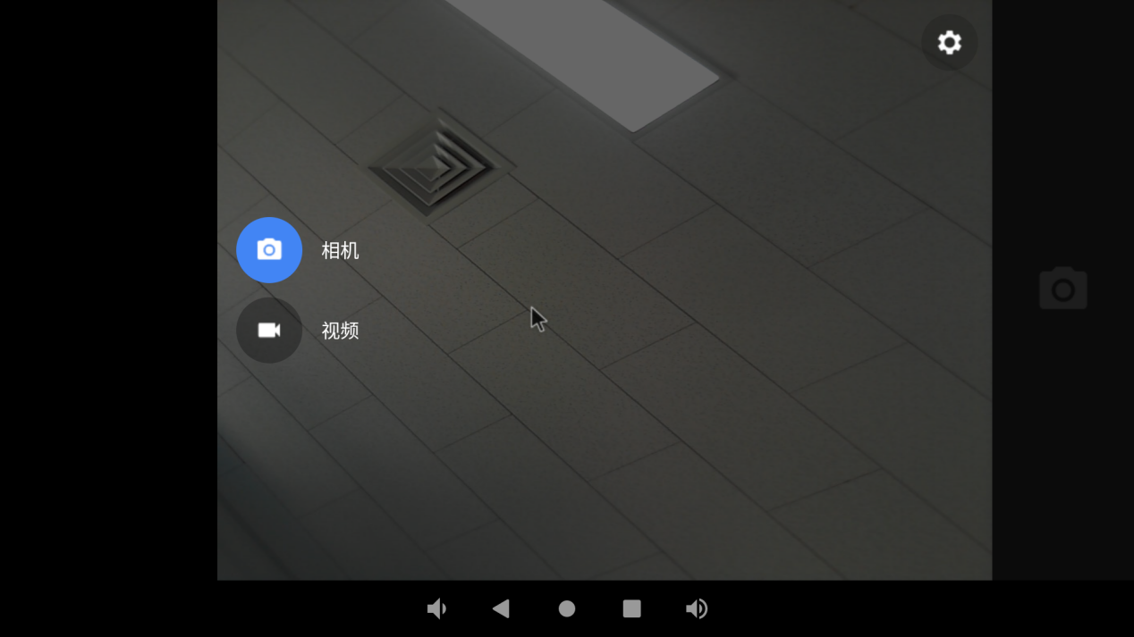
Click on the camera in the application interface:

Configure permissions:
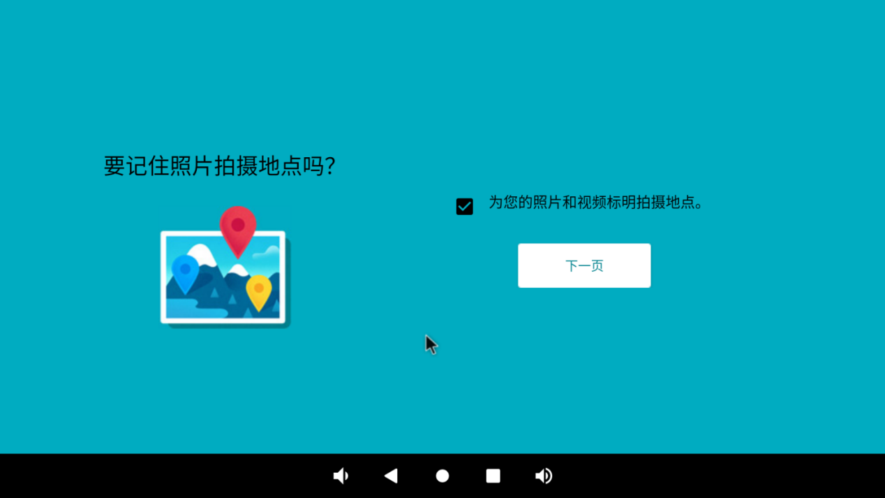
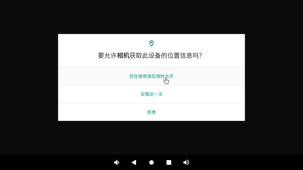
Enter the preview interface and click the photo button on the right to take a photo:
Swipe the screen to the right to open the options for switching between photo and video mode, as well as accessing settings.
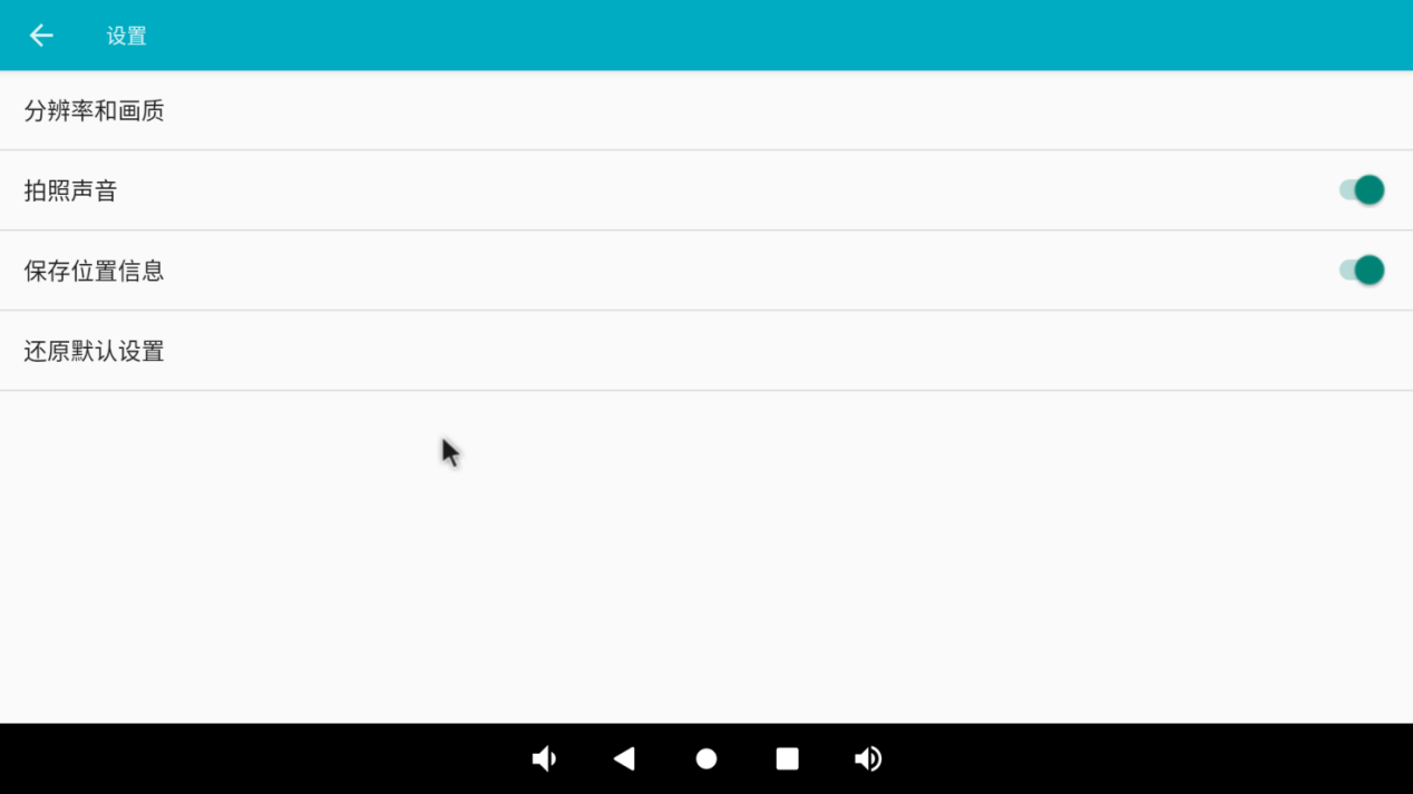
Tap on the settings button in the top right corner to adjust settings such as resolution and image quality.
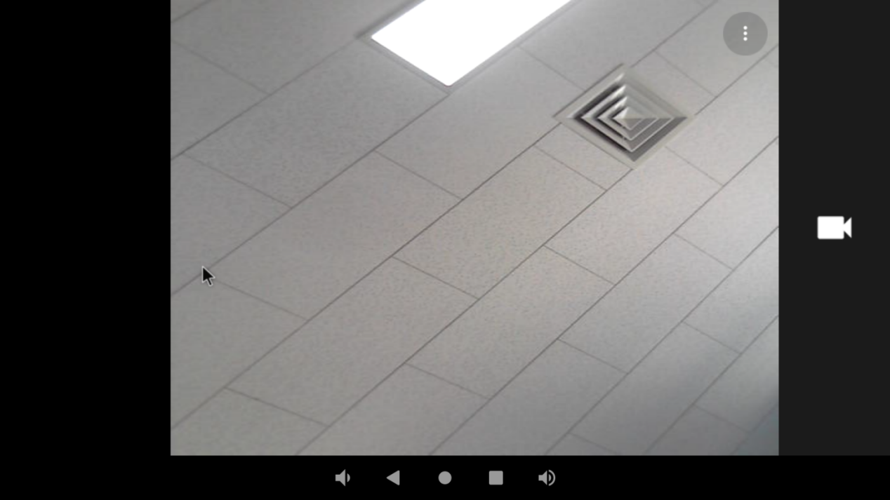
Click the video button to enter the video preview interface:
Click the video button to record the video:
3.22.2 MIPI Camera Test
Power down the board and connect the ov13850 to the board’s MIPI CSI interface. The test method of MIPI Camera is the same as that of UVC Camera and will not be repeated here.
3.23 HDMI Resolution Setting Test
OK3568 platform supports dynamic setting of HDMI resolution.
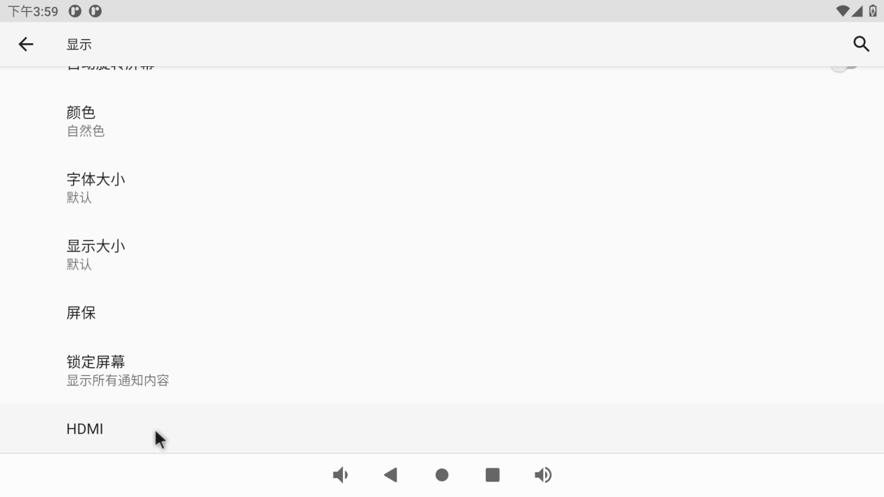
Click “ ”, on the application interface to enter the setting interface:
Click “Display”, select “Advanced”, and click “HDMI” to configure HDMI:
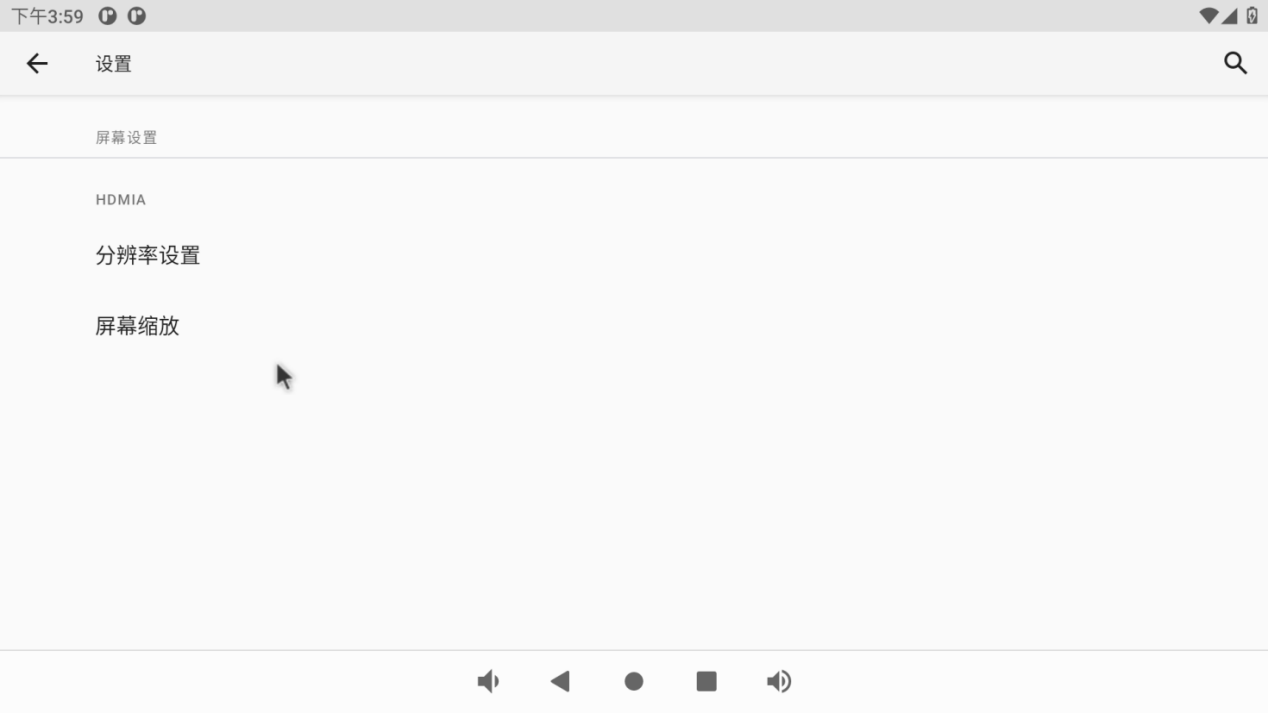
You can dynamically select the desired resolution based on the resolution supported by the current HDMI screen:
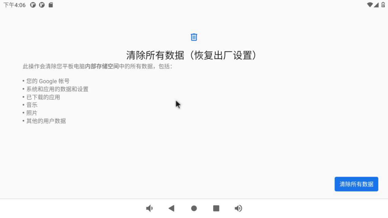
3.24 Factory Reset
The OK3568 platform supports restoring factory settings.
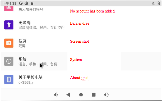
Click “ ”, on the application interface to enter the setting interface:
Click “System”:
Click “Reset option” and select “Clear all data (restore factory settings)”:
Click “Clear all data”:
Then click “Clear All Data”.
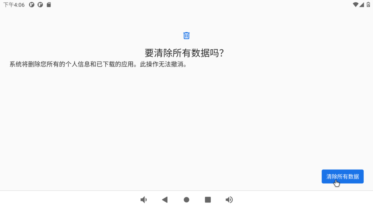
Wait for OK3568 to restore the default factory settings. Please do not power off during the process of restoring the factory settings.
3.25 APK Installation With TF Card
After loading the TF card according to the previous steps, you can see an APK file after entering the TF card directory.
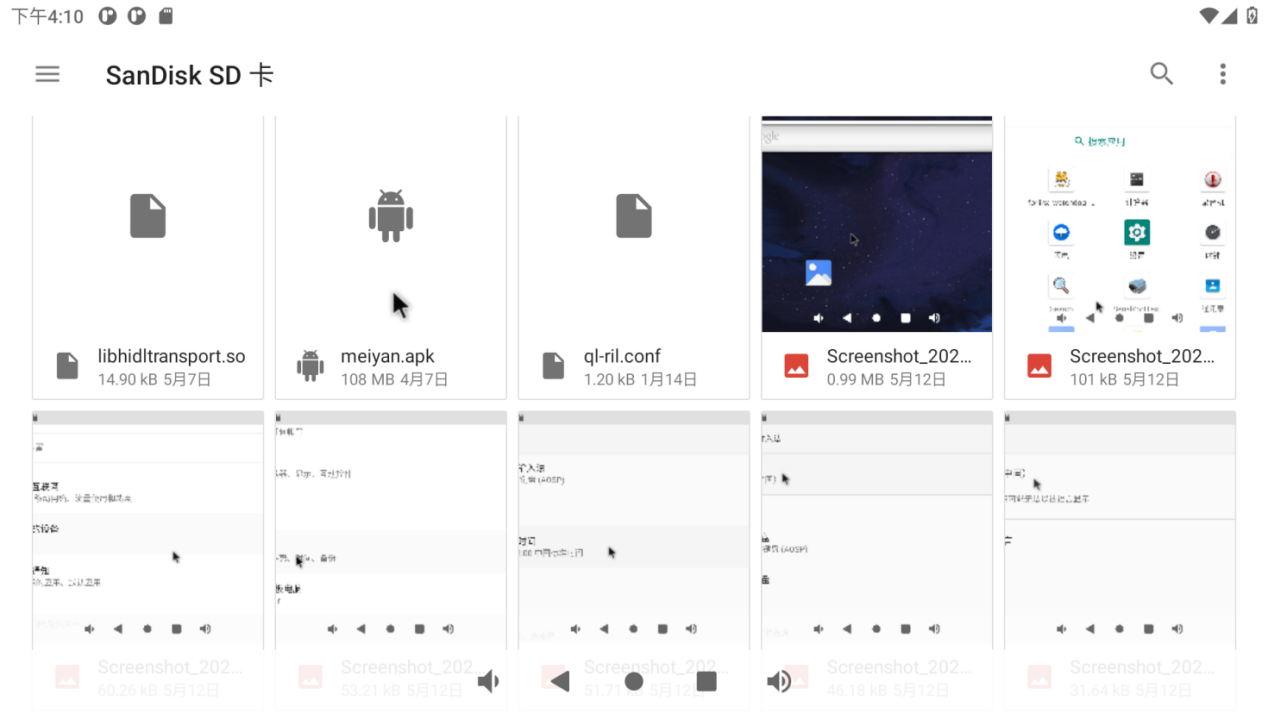
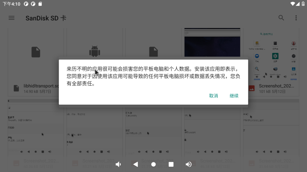
Double-click the APK file to install and configure permissions:
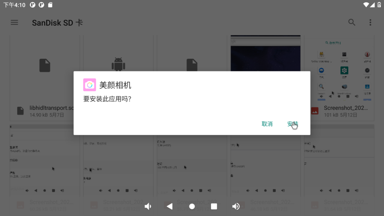
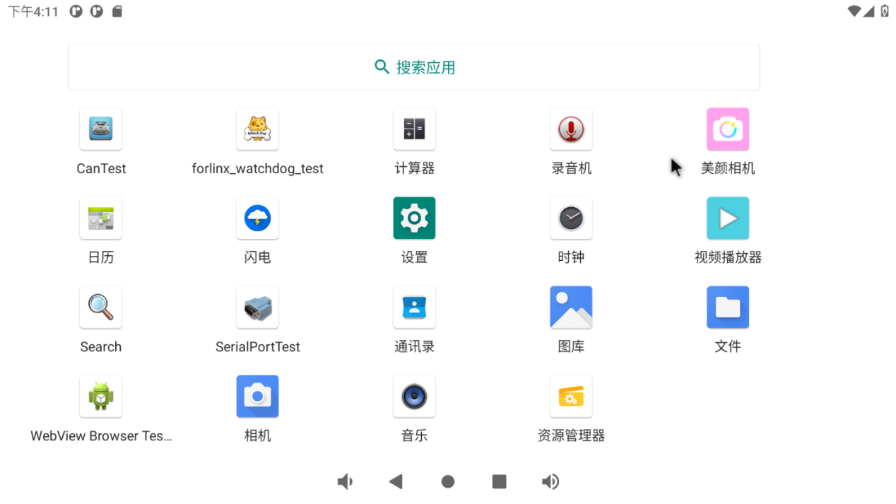
Click “Install” to complete the installation:

4. System Flashing
4.1 OTG System Flashing
4.1.1 OTG Driver Installation
Path: OK3568-C (Android) User Profile \ 2-Image and Source Code \ Tools</font>DriveAssitant-v5.11.zip
Extract the above path file to any directory and run it with administrator privileges
Open DriverInstall.exe.
Click “Driver Installation”.
4.1.2 OTG Full Flashing Test
4.1.2.1 RKDevTool Full Package Flashing
️Path: OK3568-C (Android) User Profile \ 2-Images and Source Code \ Tools \ RKDevTool_Selease-v2.86.rip
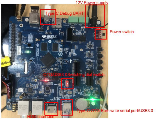
It is a development tool provided by Rockchip. Before use, please unzip it to a directory with an all-English path. Connect the development board to the host using a Type-C cable. Press and hold the recovery key on the development board without releasing it, then press the reset key to reset the system. Release the recovery key approximately two seconds later. The Rockchip development tool will prompt the discovery of the loader device. There will be prompts on the Rockchip development tool : loader device found
Note: The condition for recognition is that the development board is powered up and the recover key is in the pressed state.
Theoretically, Rockchip development tools have no requirements for the unzip directory. However, some users have feedback that the unzip directory should be in full English. If the tool doesn’t match the following figure, please consider unzipping it in an English directory.
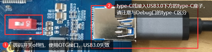
Note: Pay attention to two points during OTG programming: 1. Link the OTG line. 2. If OTG is multiplexed with the USB 3.0, it is necessary to modify the dial switch, as shown in the following figure:
Open the Rockchip development tool:
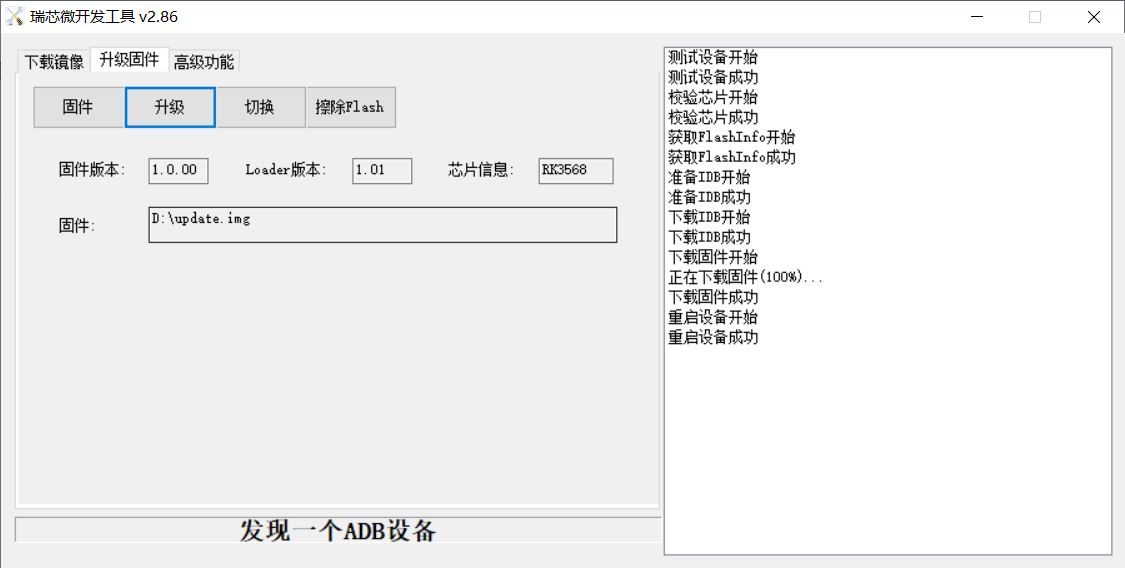
Click the “Upgrade Firmware” tab, click the “Firmware” button to select the full upgrade image update.img. The program will be parsing the firmware, so wait a while.
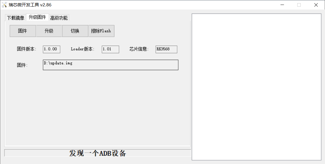
Click “Switch” and wait for a while to enter the LOADER device, then click “Erase Flash” to erase. Then click the “Upgrade” button to upgrade.
Introduction to MASKROM mode
If the loader is damaged and cannot enter the Loader mode, press and hold the red Maskrom key and then press the reset key to enter the maskrom mode for flashing.
At this time, the system will prompt the discovery of a maskrom device. The flashing process is consistent with the loader mode, so it is best to use an update.img burning.
Note: Don’t click “Device Partition Table” in maskrom mode, it is invalid.
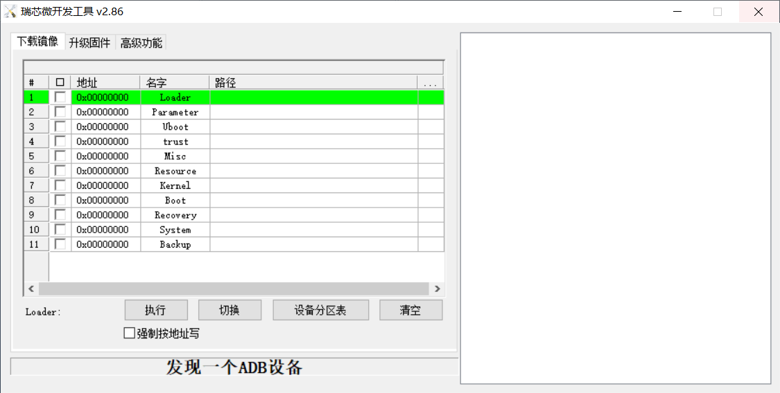
4.1.2.2 RKDevTool Separate Flashing Test
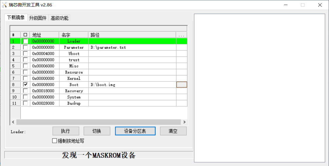
First let the development board be in LOADER state, and then open the RKDevTool:
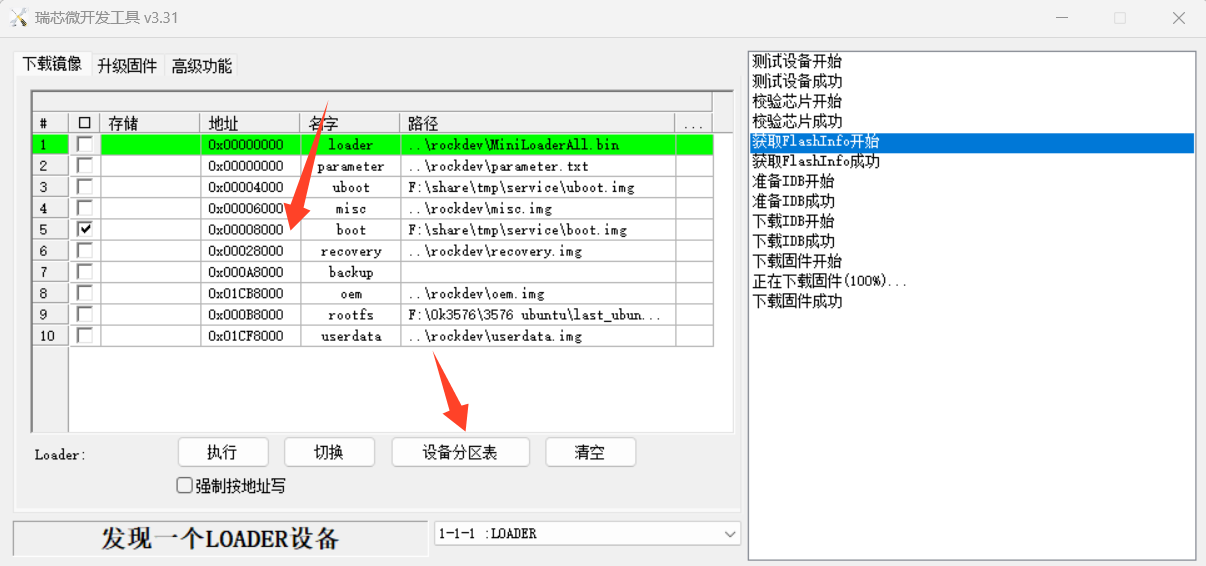
Click the device partition table to obtain the burning address of each partition, set a separate mirror path, and finally click Execute.
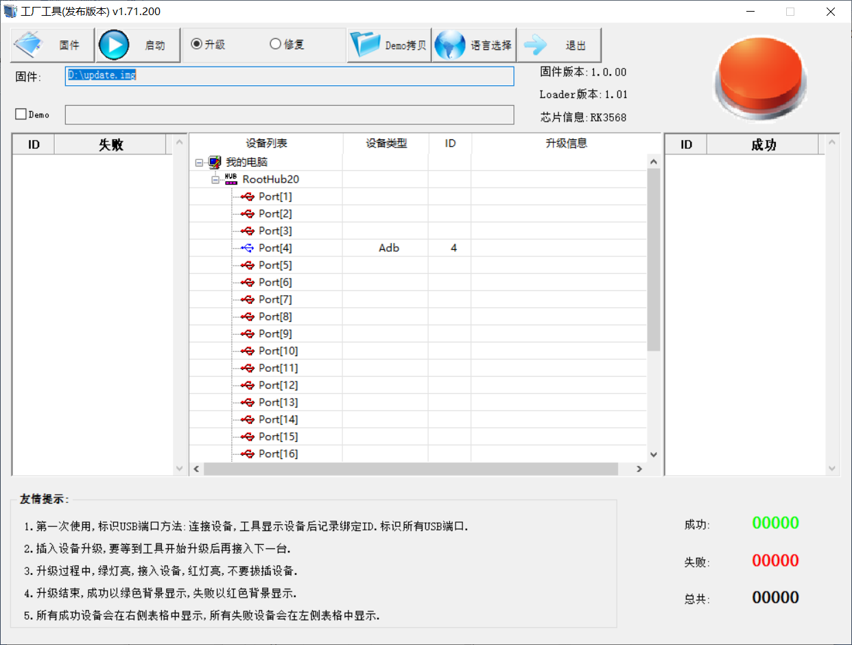
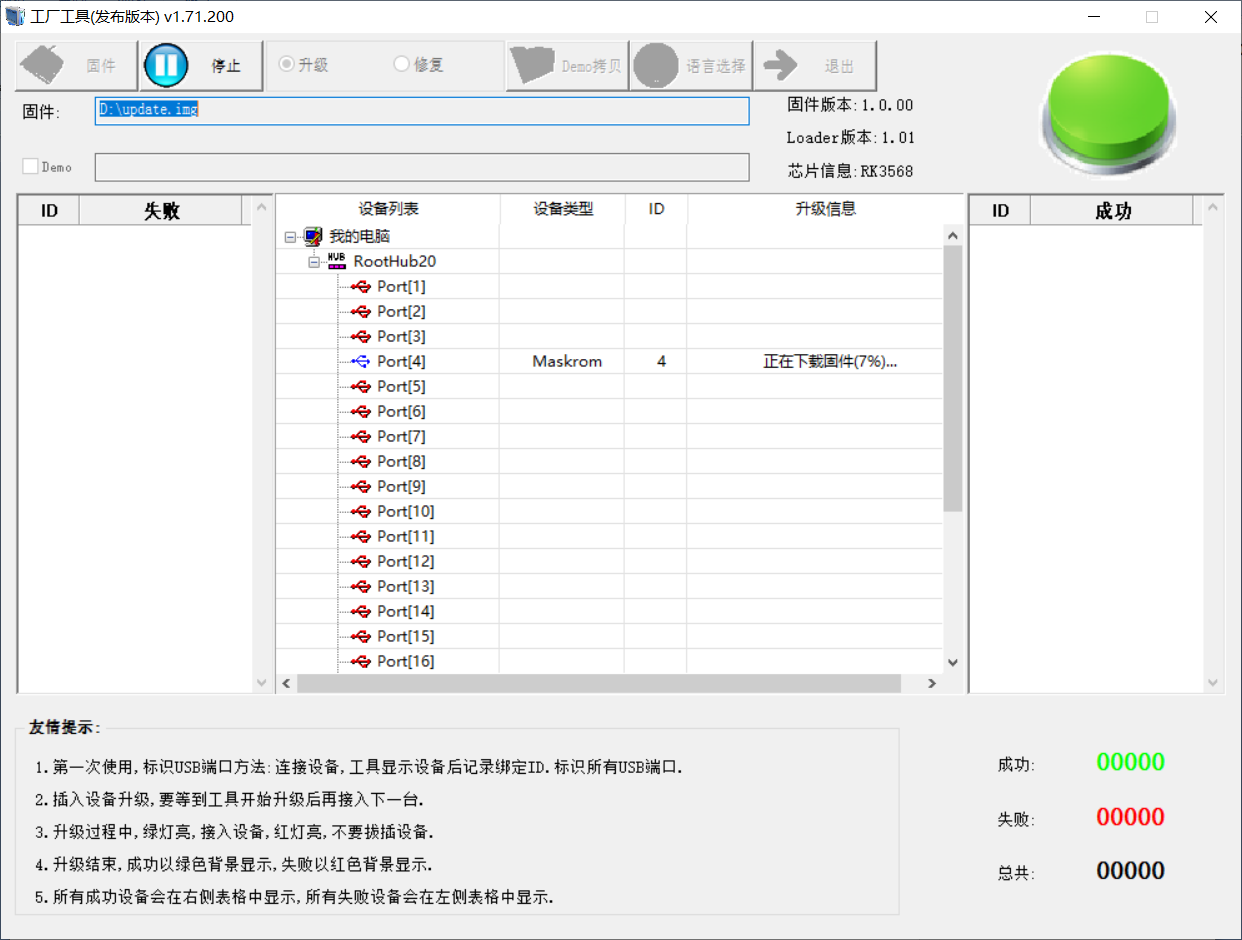
4.1.2.3 Factory Tool Flashing Test
FactoryTool is a factory batch OTG burning tool. It does not need to read the image and can do batch burning. In addition, it can burn some larger image files. If RKDevTool compatibility is not satisfied, you can try this method. Before using it, unzip it to a full English path, connect the development board and host computer with a Type-C cable, press and hold the recover button of the development board and don’t release it, then press the reset button to reset the system, and release the recover button after about two seconds. There will be prompts on the Rockchip development tool : loader device found
**Note: **
The condition for recognition is that the development board is powered up and the recover key is in the pressed state.
Theoretically, Rockchip development tools have no requirements for the unzip directory. However, some users have feedback that the unzip directory should be in full English. If the tool doesn’t match the following figure, please consider unzipping it in an English directory.
Open the Rockchip development tool:
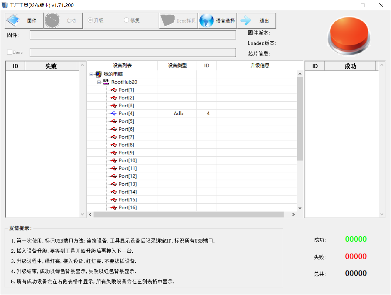
Click to select the firmware, and click to start. At this time to recognize the loader device will automatically start burning.
4.2 TF Card Flashing
Production and test of programming TF card:
**Note: **
The maximum tested capacity of the TF card is 16G. Using a TF card with 32G or above may result in a flashing failure;
When flashing the TF card, it will also enter the command line as the root@buildroot user. Please wait patiently for the flashing to complete.
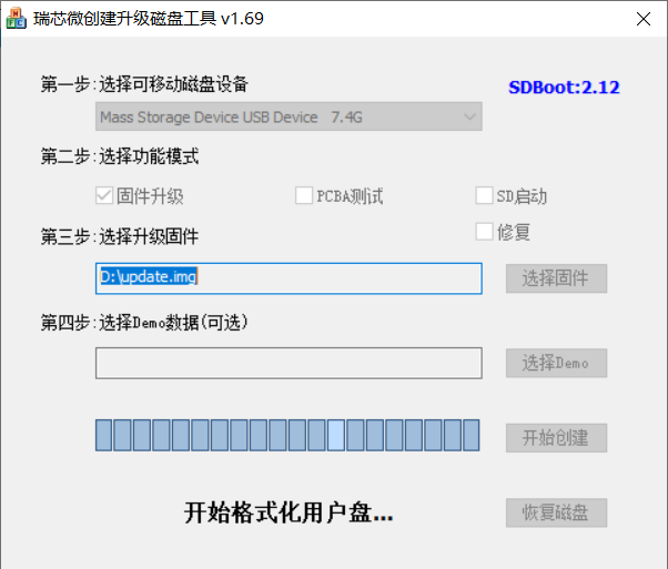
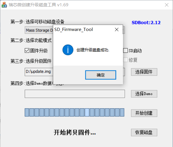
Copy SDDiskTool_v1.69.zip from the user profile tools directory to any directory on windows. Run SD_Firmware_Tool.exe with administrator privileges.
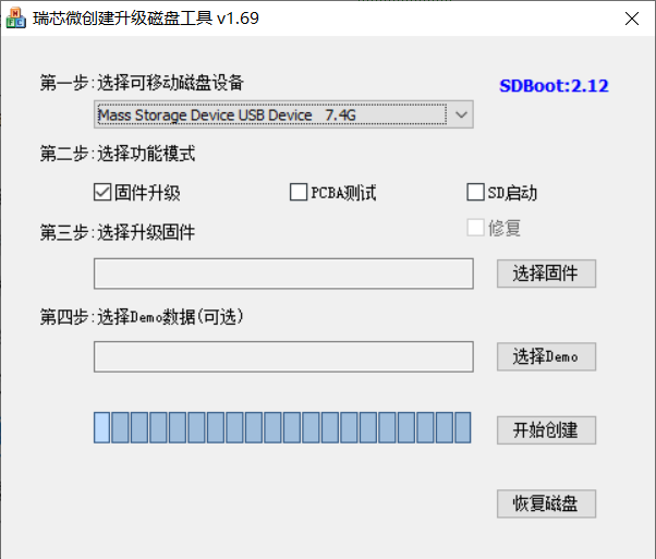
Select the disk device, check “Firmware Upgrade” and select update.img. Click Start Creating.
Insert the TF card into the development board and start, the system will automatically enter the flashing process. When the flashing is complete, both the screen and the serial port will prompt:
Doing Actions succeeded.please remove the sdcard……
At this time, pull out the TF card, the system automatically restarts (please do not power down directly).
Burning status serial port information:
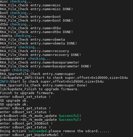
If the automatic restart does not occur after removing the TF card, a manual restart can also complete the burning. Please be patient during the burning process.