IPC_SDK_Linux6.1.157_User’s Manual_V1.0
Document classification: □ Top secret □ Secret □ Internal information ■ Open
Copyright
The copyright of this manual belongs to Baoding Folinx Embedded Technology Co., Ltd. Without the written permission of our company, no organizations or individuals have the right to copy, distribute, or reproduce any part of this manual in any form, and violators will be held legally responsible.
Forlinx adheres to copyrights of all graphics and texts used in all publications in original or license-free forms.
The drivers and utilities used for the components are subject to the copyrights of the respective manufacturers. The license conditions of the respective manufacturer are to be adhered to. Related license expenses for the operating system and applications should be calculated/declared separately by the related party or its representatives.
Application Scope
This manual is a software manual for the IPC SDK, which carries out relevant functional tests and descriptions targeting the IPC SDK Linux 6.1.157 kernel. Please select the materials consistent with the image in the development board for operations. You can access software and hardware documentation through the cloud storage link provided by our company (please ask your sales representative for the download link).
Note:
The OK1126B-C development board comes pre-flashed with the default Linux version 6.1.147. However, this version is not the IPC SDK Linux version 6.1.157 mentioned in this document. Before any operations, you must re-flash the board with the IPC SDK Linux 6.1.157 image. Please refer to the section on “System Flashing” for the flashing instructions. Once the flashing is complete, you can verify the kernel version information by following the steps outlined in “Serial Port Login”;
For detailed information, please refer to the OK1126B-C User Materials. All file paths for user materials mentioned in this document are relative to the root directory of the OK1126B-C User Materials.
Revision History
Date |
Version |
SoM Version |
Carrier Board Version |
Revision History |
|---|---|---|---|---|
26/08/2026 |
V1.0 |
V1.1 |
V1.1 |
OK1126B-C IPC SDK Linux6.1.157 User’s Manual Initial Version |
Overview
This manual is designed to help you quickly familiarize yourselves with the product, understand interface functions, and learn testing methods. It primarily covers the testing of development board interface functions, methods for flashing the image, and troubleshooting common issues encountered during use. During testing, certain commands have been annotated for better understanding, focusing on practicality and adequacy. For kernel compilation, related application compilation methods, and development environment setup, please refer to the “User’s Compilation Manual” provided by Forlinx..
There are six chapters:
Chapter 1. briefly introduces the development board’s interface resources, relevant driver paths in the kernel source code, supported flashing and boot methods, and key points in the documentation;
Chapter 2. describes the login method: serial port login;
Chapter 3. conducts functional tests on the product through command-line operations;
Chapter 4. performs tests on the product’s low-power consumption related functions;
Chapter 5. carries out multimedia function tests for the product;
Chapter 6. introduces the programming method of the product.
1. OK1126B-C Development Board Description
OK1126B-C/OK1126BJ-C is a low-power and high-performance processor based on the ARM64 architecture. It consists of 4 Cortex-A53 cores and integrates NEON, FPU, NPU and MCU. The NPU has a computing power of up to 3.0 TOPs, which can be used for artificial intelligence applications such as smart vision.
Connection method: Board to board. The main interfaces are shown in the figure below:
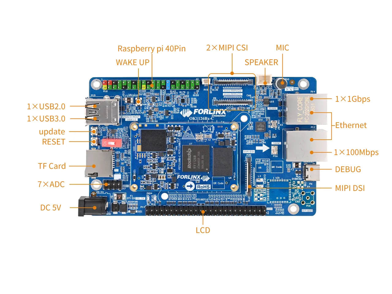
Front
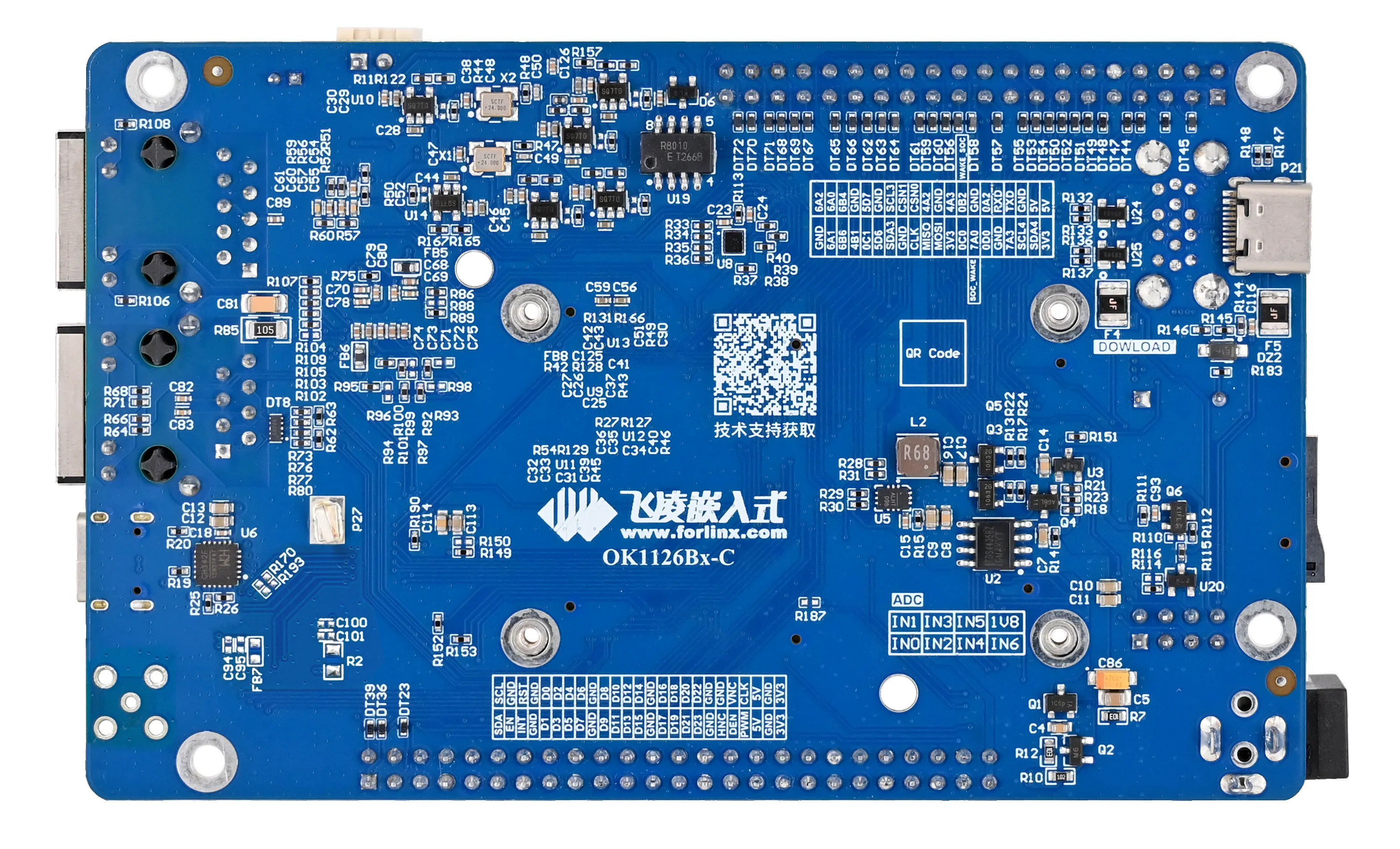
Back
Note: Hardware parameters are not discussed further in this software manual. Before proceeding with software development based on this manual, please read the “OK1126B-C/OK1126BJ-C Hardware Manual” located in the “Hardware Resources\User Manual” directory. This will help you understand the product naming conventions and the hardware configuration of the unit you are using, thereby facilitating your effective use of this product.
1.1 IPC SDK Linux 6.1.157 System Software Resources
Device |
Driver Source Code Location in the Kernel |
Device Name |
|---|---|---|
LCD Backlight Driver |
drivers/video/backlight/pwm_bl.c |
/sys/class/backlight |
USB Interface: |
drivers/usb/storage/ |
|
USB Mouse |
drivers/hid/usbhid/ |
/dev/input/mice |
Ethernet |
drivers/net/ethernet/stmicro/stmmac |
|
SD/micro TF card driver |
drivers/mmc/host/dw_mmc-rockchip.c |
/dev/block/mmcblk1pX |
EMMC Driver |
drivers/mmc/host/dw_mmc-rockchip.c |
/dev/block/mmcblk2pX |
OS04A10 |
drivers/media/i2c/os04a10.c |
/dev/videoX |
LCD controller |
drivers/gpu/drm/rockchip/rockchip_drm_vop.c |
|
MIPI CSI |
drivers/phy/rockchip/phy-rockchip-mipi-rx.c |
|
MIPI DSI |
drivers/phy/rockchip/phy-rockchip-inno-mipi-dphy.c |
|
LCD touch driver |
drivers/input/touchscreen/gt9xx/* |
/dev/input/eventX |
RTC Real - Time Clock |
drivers/rtc/rtc-rx8010.c |
/dev/rtc0 |
Serial Port |
drivers/tty/serial/8250/8250_dw.c |
/dev/ttySX |
LED |
drivers/leds/leds-gpio.c |
|
I2S |
sound/soc/rockchip/rockchip_i2s.c |
|
Audio Driver |
;background-color:rgb(248, 248, 248);”>sound/soc/codecs/rk3506_codec.c |
/dev/snd/ |
Watchdog |
drivers/watchdog/dw_wdt.c |
|
SPI |
drivers/spi/spi-rockchip.c |
1.2 eMMC Storage Partition Table
The table below details the eMMC storage partition information for the Linux operating system (The size of a block is 512 bits when calculating.):
Partition Index |
Name |
Offset/Block |
Size/Block |
Content |
|---|---|---|---|---|
1 |
env |
0x00000000 |
0x00000040 |
env.img |
2 |
idblock |
0x00000040 |
0x00000400 |
idblock.image |
3 |
uboot |
0x00000440 |
0x00002000 |
uboot.img |
4 |
boot |
0x00002440 |
0x00020000 |
boot.img |
5 |
userdata |
0x00022440 |
0x00e00000 |
userdata.img |
2. Fast Startup
2.1 Preparation Before Startup
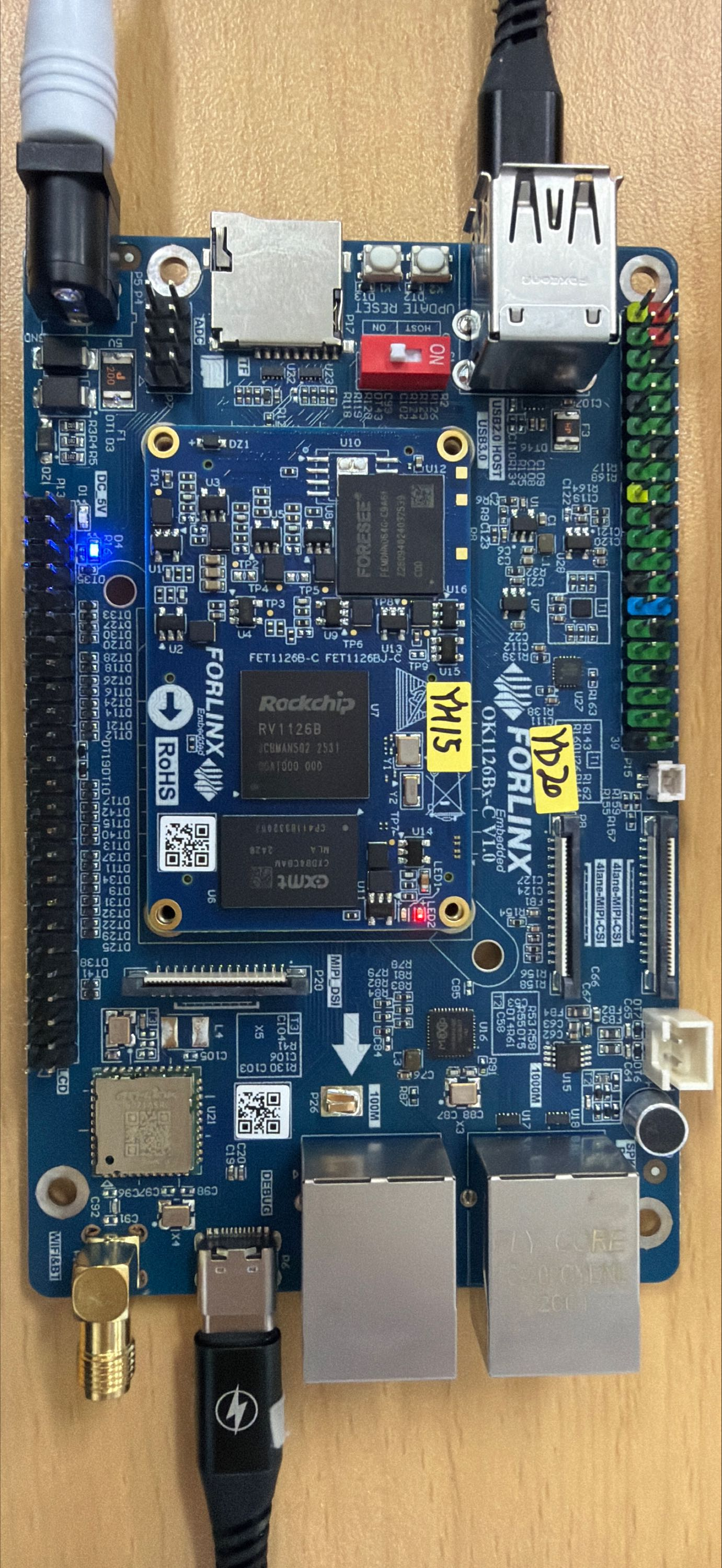
5V2A DC Power Cable
Debug port cable
2.2 Debugging Serial Port Driver Installation
OK1126B-C/ The OK1126BJ-C platform features a Type-C port for serial debugging and an onboard USB-to-UART chip. No additional USB-to-serial debugging tool is required, making the setup simple and convenient.
To install the driver, please use the driver package CH343SER.EXE provided in the \” Table of Contents 3- Tools directory of the software materials.
2.3 Serial Port Login
2.3.1 Serial Connection Settings
Note:
Serial Port Interrupt Login User: No login required by default;
Serial Port Settings: Baud rate 115200, 8 data bits, 1 stop bit, no parity bit, no flow control;
Hardware Requirements: Type-C for connecting PC and development board;
Software Requirements: For the PC, a hyper terminal software installation is required. You can choose from various serial port terminal software options that you are familiar with.
Take putty as an example to introduce the setting mode of the putty terminal:
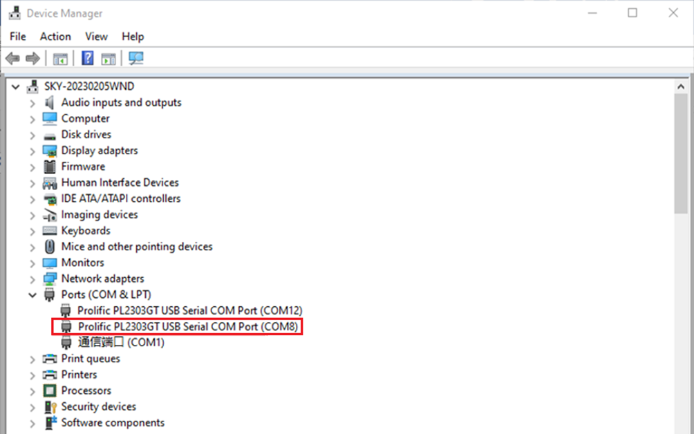
Step1: Identify the serial port number assigned to the PC. In Device Manager, locate the serial port with the name ending in “SERIAL-”, which corresponds to the actual debug UART. For example, this may appear as COM61; the port number should be based on the actual one detected by the system.
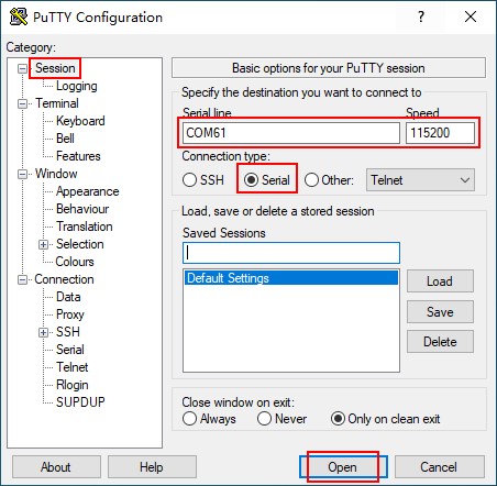
Step2: Open the putty and set the serial line according to the com port of the computer used. The baud rate is 115200.
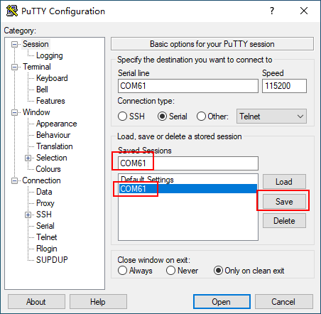
Step 3: After the above settings, input the computer’s COM port in Saved Sessions (e.g., COM61 as an example), save the settings. For subsequent serial port openings, simply click on the saved port number;
2.3.2 Serial Port Login
After the PC terminal software is configured, connect the PC and the development board using a serial cable, then power on the device after connecting the power supply. Startup information can be viewed via the terminal software.
The following startup message indicates a successful boot, and you can press Enter to create a new command line:
2.4 System Shutdown
In general, you can directly power off the system. However, if operations such as data storage or functional usage are in progress, avoid cutting power abruptly to prevent irreversible file damage, which may require re-flashing the firmware. To ensure all data is fully written, you can execute the sync command to complete data synchronization before powering off.
Note: For products designed based on the SoM:, if unexpected power loss during use leads to system abnormalities, consider implementing measures such as power-loss protection in the design.
3. OK1126B-C Command Function Test
Note: The system will automatically load the Wi-Fi module upon startup and execute udhcpc, which will generate a large amount of print information on the debugging serial port and affect the viewing experience and operations.
If you need to turn off these messages, execute the following commands:
Disable udhcpc:
killall udhcpc
Lower the kernel print level:
echo 0 > /proc/sys/kernel/printk
3.1 LED
There is a controllable blue LED on the SoM, which functions as a heartbeat indicator by default.
Set the trigger to none for user control:
echo none > /sys/class/leds/work/trigger
Turn on the LED:
echo 1 > /sys/class/leds/work/brightness
Turn off the LED:
echo 0 > /sys/class/leds/work/brightness
Set the trigger to heartbeat:
echo heartbeat > /sys/class/leds/work/trigger
3.2 TF Card
Insert a TF card in FAT32 format into the card slot (the TF card used this time has a capacity of 16GB). The serial port printout will contain the following content:
[ 2394.874097] mmc_host mmc1: Bus speed (slot 0) = 198000000Hz (slot req 200000000Hz, actual 198000000HZ div = 0)
[ 2394.883651] dwmmc_rockchip 21d60000.mmc: Successfully tuned phase to 125
[ 2394.883667] mmc1: new ultra high speed SDR104 SDHC card at address aaaa
[ 2394.883998] mmcblk1: mmc1:aaaa SA16G 14.8 GiB
[ 2394.886104]  mmcblk1: p1
Check the generated mmcblk device:
ls /dev/mmcblk*
You can see that mmcblk1p1 is generated. (If the TF card is not partitioned, only mmcblk1 will be visible. You need to use a tool to partition the TF card before mmcblk1p1 can be displayed.)
/dev/mmcblk1p1     /dev/mmcblk0p5     /dev/mmcblk0p2     /dev/mmcblk0boot0
/dev/mmcblk1       /dev/mmcblk0p4     /dev/mmcblk0p1     /dev/mmcblk0
/dev/mmcblk0rpmb   /dev/mmcblk0p3     /dev/mmcblk0boot1
Mount the TF card:
mount /dev/mmcblk1p1 /mnt/sdcard
View files in the TF card:
ls /mnt/sdcard
Write data to the TF card:
dd if=/dev/zero of=/mnt/sdcard/test.bin bs=1M count=500 conv=fsync oflag=direct
The printout is as follows:
500+0 records in
500+0 records out
524288000 bytes (500.0MB) copied, 14.634599 seconds, 34.2MB/s
Read data from the TF card:
dd if=/mnt/sdcard/test.bin of=/dev/null bs=1M count=500 iflag=direct
The printout is as follows:
500+0 records in
500+0 records out
524288000 bytes (500.0MB) copied, 6.174911 seconds, 81.0MB/s
Unmount the TF card, then pull out the TF card:
umount /mnt/sdcard
3.3 USB
3.3.1 USB3.0 OTG
3.3.1.1 ADB
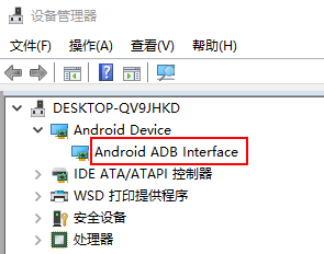
Set the DIP switch S1 on the development board to the OFF position, and ADB will run automatically after power-on. The ADB device will be seen in the Device Manager on the PC.
Execute the following command on the PC side to connect to the ADB device:
adb devices
You can see the current development board:
List of devices attached
17c53624bfba26d1        device
Currently, only one ADB device is connected to the PC, so you can directly use the following command to enter the development board terminal:
adb shell
View the files on the development board:
ls
dev       etc       media     opt       sbin      userdata  data      linuxrc
root      init      mnt       proc      sys       usr       lib32
bin       lib       oem       run       tmp       var       lib64
3.3.2 USB3.0 HOST
Note: Under HOST mode, VBUS power supply is controlled by GPIO0_C7 (serial number 23), which is disabled by default.
If you need to enable it, first execute the following command to turn on VBUS power supply:
echo 23 > /sys/class/gpio/export
echo out > /sys/class/gpio/gpio23/direction
echo 1 > /sys/class/gpio/gpio23/value
After enabling it, execute the following command if you need to disable it:
echo 0 > /sys/class/gpio/gpio23/value
Set the DIP switch S1 on the development board to the ON position, and the USB3.0 HOST interface will be available after power-on.
Insert a USB3.0 U disk into the USB3.0 HOST interface, and the terminal will display the following printout:
[14795.533064] usb 4-1: new SuperSpeed USB device number 3 using xhci-hcd
[14795.567897] usb 4-1: New USB device found, idVendor=0951, idProduct=1666, bcdDevice= 1.10
[14795.567912] usb 4-1: New USB device strings: Mfr=1, Product=2, SerialNumber=3
[14795.567922] usb 4-1: Product: DataTraveler 3.0
[14795.567930] usb 4-1: Manufacturer: Kingston
[14795.567938] usb 4-1: SerialNumber: 1C1B0D6511ECE7B1E91310C0
[14795.568616] usb-storage 4-1:1.0: USB Mass Storage device detected
[14795.569024] scsi host0: usb-storage 4-1:1.0
[14796.584702] scsi 0:0:0:0: Direct-Access     Kingston DataTraveler 3.0 PMAP PQ: 0 ANSI: 6
[14796.585111] sd 0:0:0:0: Attached scsi generic sg0 type 0
[14796.649003] sd 0:0:0:0: [sda] 121110528 512-byte logical blocks: (62.0 GB/57.8 GiB)
[14796.649852] sd 0:0:0:0: [sda] Write Protect is off
[14796.650480] sd 0:0:0:0: [sda] Write cache: disabled, read cache: enabled, doesn't support DPO or FUA
[14796.653554]  sda: sda1
[14796.653681] sd 0:0:0:0: [sda] Attached SCSI removable disk
You can see the sda1 device.
Mount the USB3.0 U disk:
mount /dev/sda1 /mnt/sdcard/
View the files in the USB3.0 U disk:
ls /mnt/sdcard/
Write data to the USB3.0 U disk:
dd if=/dev/zero of=/mnt/sdcard/test.bin bs=1M count=500 conv=fsync oflag=direct
The printout is as follows:
500+0 records in
500+0 records out
524288000 bytes (500.0MB) copied, 18.800449 seconds, 26.6MB/s
Read data from the USB3.0 U disk:
dd if=/mnt/sdcard/test.bin of=/dev/null bs=1M count=500 iflag=direct
The printout is as follows:
500+0 records in
500+0 records out
524288000 bytes (500.0MB) copied, 2.640362 seconds, 189.4MB/s
Unmount the USB3.0 U disk, then pull out the USB3.0 U disk:
umount /mnt/sdcard
3.3.3 USB2.0 HOST
Note: Under HOST mode, VBUS power supply is controlled by GPIO0_C7 (serial number 23), which is disabled by default.
If you need to enable it, first execute the following command to turn on VBUS power supply:
echo 23 > /sys/class/gpio/export
echo out > /sys/class/gpio/gpio23/direction
echo 1 > /sys/class/gpio/gpio23/value
After enabling it, execute the following command if you need to disable it:
echo 0 > /sys/class/gpio/gpio23/value
Insert a USB2.0 U disk into the USB2.0 HOST interface, and the terminal will display the following printout:
[15456.202985] usb 1-1: new high-speed USB device number 3 using ehci-platform
[15456.413899] usb 1-1: New USB device found, idVendor=0781, idProduct=5567, bcdDevice= 1.00
[15456.413914] usb 1-1: New USB device strings: Mfr=1, Product=2, SerialNumber=3
[15456.413924] usb 1-1: Product: Cruzer Blade
[15456.413932] usb 1-1: Manufacturer: SanDisk
[15456.413940] usb 1-1: SerialNumber: 03000310123123023701
[15456.414393] usb-storage 1-1:1.0: USB Mass Storage device detected
[15456.414764] scsi host0: usb-storage 1-1:1.0
[15457.454091] scsi 0:0:0:0: Direct-Access     SanDisk  Cruzer Blade     1.00 PQ: 0 ANSI: 6
[15457.459535] sd 0:0:0:0: Attached scsi generic sg0 type 0
[15457.472037] sd 0:0:0:0: [sda] 60125184 512-byte logical blocks: (30.8 GB/28.7 GiB)
[15457.473408] sd 0:0:0:0: [sda] Write Protect is off
[15457.474451] sd 0:0:0:0: [sda] Write cache: disabled, read cache: enabled, doesn't support DPO or FUA
[15457.498452]  sda: sda1
[15457.498668] sd 0:0:0:0: [sda] Attached SCSI removable disk
You can see the sda1 device.
Mount the USB2.0 U disk:
mount /dev/sda1 /mnt/sdcard/
View the files in the USB2.0 U disk:
ls /mnt/sdcard/
Write data to the USB2.0 U disk:
dd if=/dev/zero of=/mnt/sdcard/test.bin bs=1M count=500 conv=fsync oflag=direct
The printout is as follows:
500+0 records in
500+0 records out
524288000 bytes (500.0MB) copied, 48.371022 seconds, 10.3MB/s
Read data from the USB2.0 U disk:
dd if=/mnt/sdcard/test.bin of=/dev/null bs=1M count=500 iflag=direct
The printout is as follows:
500+0 records in
500+0 records out
524288000 bytes (500.0MB) copied, 17.003646 seconds, 29.4MB/s
Unmount the USB2.0 U disk, then pull out the USB2.0 U disk:
umount /mnt/sdcard
3.4 ADC
The SAR ADC0–6, which has a range of 1.8 V, is routed out from pin P7 on the development board. To display the ADC values for each corresponding pin, run the following commands. You can verify the results by applying different voltages to the respective pins..
cat /sys/bus/iio/devices/iio:device0/in_voltage0_raw
cat /sys/bus/iio/devices/iio:device0/in_voltage1_raw
cat /sys/bus/iio/devices/iio:device0/in_voltage2_raw
cat /sys/bus/iio/devices/iio:device0/in_voltage3_raw
cat /sys/bus/iio/devices/iio:device0/in_voltage4_raw
cat /sys/bus/iio/devices/iio:device0/in_voltage5_raw
cat /sys/bus/iio/devices/iio:device0/in_voltage6_raw
The results are as follows:
8191
431
806
871
676
537
510
The method to convert to the actual voltage value is: multiply in_voltage*_raw by in_voltage_scale. For example, if in_voltage1_raw is 431, print out the value of in_voltage_scale:
cat /sys/bus/iio/devices/iio:device0/in_voltage_scale
in_voltage_scale is 0.219726562, and the product of in_voltage1_raw and in_voltage_scale is 94.7, in millivolts (mV).
3.5 RTC
There is an external RTC on the development board, and the corresponding device is/dev/rtc0. The rv1126b also has a built-in RTC, and the corresponding device is/dev/rtc1, which is related to the wake-up in AOA and AOV modes. If the RTC function is needed during the development process, /dev/rtc0 can be used.
Connect the RTC battery, set the system software time
date -s "2023-12-12 17:23:00"
Synchronize the system software time to the hardware RTC
hwclock -w -f /dev/rtc0
Read the hardware RTC time
hwclock -r -f /dev/rtc0
Check if it is consistent with the set system software time. With the RTC battery connected, power off the development board and then power it on again, continue to execute the command to read the hardware RTC time, and verify whether the hardware RTC time is correct.
3.6 UART
The UART available for using on the development board is uart5, located at pins 8 and 10 of P18, as shown in the figure below.
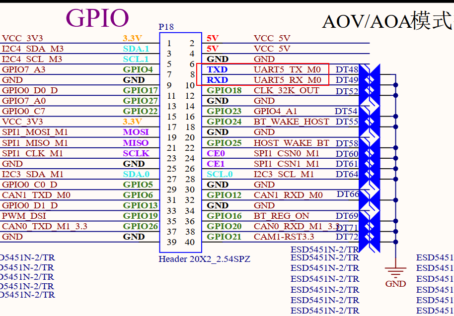
Copy User Materials/2-Images and Source Codes/2-Test Programs/uart/fltest_uarttest to the /userdata path of the development board (via TF card, U disk or ADB, please refer to the corresponding sections for operations).
cp /mnt/sdcard/fltest_uarttest /userdata/
Use a jumper cap to short-circuit pins 8 and 10, and run the following command for testing:
/userdata/fltest_uarttest -d /dev/ttyS5
The results are as follows:
Welcome to uart test
Send test data:
forlinx_uart_test.1234567890...
Read Test Data finished,Read:
forlinx_uart_test.1234567890...
If the jumper cap is not connected, the second half at the beginning of “Read” will not be printed and the program will be blocked.
3.7 SPI
The SPI available on the development board is spi1, located at pins 19, 21, 23, 24 and 26 of P18, as shown in the figure below.
The corresponding relationships are as follows:
Pin |
Function |
|---|---|
19 |
MOSI |
21 |
MISO |
23 |
CLK |
24 |
CS0 |
26 |
CS1 |
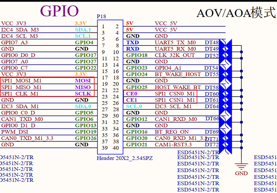
Copy User Materials/2-Images and Source Codes/2-Test Programs/spi/fltest_spidev_test to the /userdata path of the development board (via TF card, U disk or ADB, please refer to the corresponding sections for operations).
cp /mnt/sdcard/fltest_spidev_test /userdata/
Use a jumper cap to short-circuit pins 19 and 21, and run the following command for testing:
/userdata/fltest_spidev_test -D /dev/spidev1.0
The printout is as follows:
spi mode: 0
bits per word: 8
max speed: 500000 Hz (500 KHz)

FF FF FF FF FF FF
40 00 00 00 00 95
FF FF FF FF FF FF
FF FF FF FF FF FF
FF FF FF FF FF FF
DE AD BE EF BA AD
F0 0D
Remove the jumper cap and run the program again, the printout is as follows:
spi mode: 0
bits per word: 8
max speed: 500000 Hz (500 KHz)

FF FF FF FF FF FF
FF FF FF FF FF FF
FF FF FF FF FF FF
FF FF FF FF FF FF
FF FF FF FF FF FF
FF FF FF FF FF FF
FF FF
3.8 Ethernet
The development board features two Ethernet ports: one is a Gigabit Ethernet port connected via an external Gigabit PHY, and the other is a Fast Ethernet port (100 Mbps) utilizing the internal Fast PHY. Since the RV1126B chip has only one GMAC channel, the Gigabit Ethernet and Fast Ethernet cannot be used simultaneously, with Gigabit set as the default option. To use Fast Ethernet, you will need to modify the device tree. The Fast Ethernet section will provide instructions on how to make these modifications.
3.8.1 Gigabit Ethernet
P14 is the Gigabit Ethernet socket, connect it with a network cable that supports Gigabit speed.
3.8.1.1 Static IP
IP: 172.20.0.139
Subnet mask: 255.255.255.0
Gateway 172.20.0.1
DNS: Take 114.114.114.114 as an example:
Enter the following commands in sequence:
Configure the IP address and subnet mask
ifconfig eth0 172.20.0.139 netmask 255.255.255.0
Configure the gateway
route add default gw 172.20.0.1
Configure the DNS (needs to be reconfigured every time the device starts up)
echo "nameserver 114.114.114.114" > /etc/resolv.conf
Ping Baidu to verify if it can access the Internet
ping www.baidu.com -I eth0
The following printout indicates that it can access the Internet:
PING www.baidu.com (220.181.111.232): 56 data bytes
64 bytes from 220.181.111.232: seq=0 ttl=53 time=12.809 ms
64 bytes from 220.181.111.232: seq=1 ttl=53 time=11.712 ms
64 bytes from 220.181.111.232: seq=2 ttl=53 time=16.423 ms
64 bytes from 220.181.111.232: seq=3 ttl=53 time=12.557 ms
64 bytes from 220.181.111.232: seq=4 ttl=53 time=12.460 ms
64 bytes from 220.181.111.232: seq=5 ttl=53 time=11.739 ms
^C
--- www.baidu.com ping statistics ---
6 packets transmitted, 6 packets received, 0% packet loss
round-trip min/avg/max = 11.712/12.950/16.423 ms
3.8.1.2 Dynamic IP
Connect the development board to the router via a network cable. The device will automatically start udhcpc to obtain information such as the IP address after power-on. The printout after successful acquisition is as follows:
udhcpc: broadcasting discover
udhcpc: broadcasting select for 192.168.124.3, server 192.168.124.1
udhcpc: lease of 192.168.124.3 obtained from 192.168.124.1, lease time 86400
deleting routers
adding dns 192.168.124.1
udhcpc: no lease, forking to background
Just directly ping one website to test the network connection.
ping www.baidu.com -I eth0
PING www.baidu.com (220.181.111.232): 56 data bytes
64 bytes from 220.181.111.232: seq=0 ttl=52 time=13.886 ms
64 bytes from 220.181.111.232: seq=1 ttl=52 time=12.893 ms
^C
--- www.baidu.com ping statistics ---
2 packets transmitted, 2 packets received, 0% packet loss
round-trip min/avg/max = 12.893/13.389/13.886 ms
3.8.2 Fast Ethernet (100Mbps Ethernet)
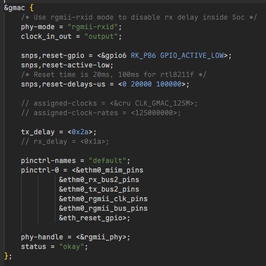
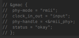
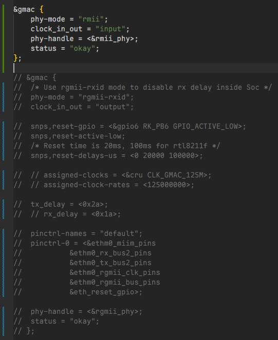
P12 is the Fast Ethernet socket. The device tree enables Gigabit Ethernet by default. To use Fast Ethernet, you need to modify the device tree, recompile and burn the image. The modification method of the device tree is as follows:
In sysdrv/source/kernel/arch/arm64/boot/dts/rockchip/OK1126B-C-common.dtsi:
Comment out this part of the code below
Uncomment this part of the code below
Change the status of the rgmii_phy node to disabled
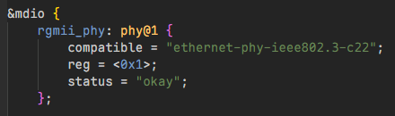
Change the status of rmii_phy to okay
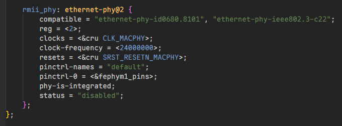
The pictures above are screenshots before modification, that is, in the state of enabling Gigabit Ethernet. The following shows the modified state (in the state of enabling Fast Ethernet):
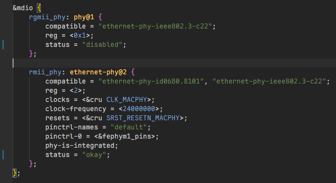
After that, perform a full recompilation and burn the image to the development board. Note that when using Fast Ethernet, the network cable should be connected to the Fast Ethernet socket, which is P12.
The remaining static IP and dynamic IP test methods are the same as those for Gigabit Ethernet.
4. OK1126B-C Low-Power Related Function Testing
4.1 AOA(Always On Audio)
4.1.1 Voice Wake-Up
Connect a speaker, and run the AOA test routine by executing the following command:
# Step 1: Clear the timer count
io -4 0x20834310 0

# Step 2: Run the AOA test routine
sample_aoa_capture -m 1 -w 2 -S 450 -f /oem/usr/share/vqefiles/fw_aad_aivad.bin -a /oem/usr/share/vqefiles/config_aivqe_aad_wakeup.json
Code path: project/app/aov_sample/sample_aoa_capture.c
After running the routine, the development board will enter the sleep state and can be woken up via a wake word.
Wake word: Xiao Rui Xiao Rui
When the wake word is detected, the device will respond with the prompt: I am here
After waking up, the board supports recognizing the following voice commands:
Turn on the light
Turn off the light
Turn on the dimmable light
Turn off the dimmable light
Turn on the spotlight
Turn off the spotlight
Turn on the downlight
Turn off the downlight
Turn on the light strip
Turn off the light strip
Turn on hydronic system
Turn off hydronic system
Turn on outdoor air system
Turn off outdoor air system
Turn on the air conditioner
Turn off the air conditioner
Open the curtain
Close the curtain
Pause the curtain
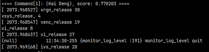
Example: Say “Xiao Rui Xiao Rui” to the on-board MIC. After hearing the response “I am here”, say the command “Turn on the light” to the on-board MIC. The debug serial port will print characters similar to the content in the corresponding figure, indicating that the “Turn on the light” command has been recognized.
4.2 AOV(Always On Video)
4.2.1 Human Detection
Connect the OS04A10 camera to the P8 interface of the development board.
Run the AOV human detection routine by executing the following command.
sample_aov_vi_iva_venc -w 1920 -h 1080 -a /etc/iqfiles/ --suspend_time 1000 --low_power 1
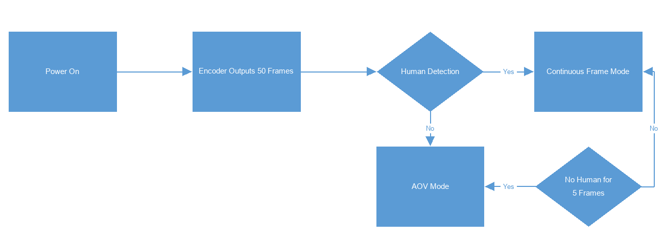
Program flow:
Code path: project/app/aov_sample/sample_aov_vi_iva_venc.c
When a person appears in the camera’s field of view, the program will automatically switch to the continuous frame mode. Otherwise, the device will wake up once every suspend_time period to detect whether there is a person in a single frame.
You can insert a TF card, and add the –enable_save_mp4 parameter to record the video footage to the TF card:
sample_aov_vi_iva_venc -w 1920 -h 1080 -a /etc/iqfiles/ --suspend_time 1000 --low_power 1 --enable_save_mp4 1
You can press Ctrl+C during the wake-up process to terminate the program, then view the video file wakeup_video_0\chn_0_count_0.mp4 in the TF card on a PC.
4.3 Sleep Wakeup
Clear the timer count with the command:
io -4 0x20834310 0
Enter the sleep state with the command:
echo mem > /sys/power/state
At this point, you will see the SoM enter the sleep state, with all indicator lights off.
Short press the WAKE key on the development board to wake it up. After waking up, the indicator lights will light up normally, and the heartbeat light will flash.
4.4 Low-Power 4G
4.4.1 Hardware Requirements
4G Module (LuatOS Air780EPT Development Board): 1 wakeable 4G_WAKE_GPIO;
1 regular 4G_NORMAL_GPIO. A data-enabled SIM card must be inserted into the 4G module;
FET1126B-C SoM: 1 x wakeable 1126B_WAKE_GPIO; 1 x regular RK_NORMAL_GPIO;
It is recommended to use a 4G module that supports low power consumption, with a built-in independent network protocol stack. This type of module can connect to external servers independently, maintain 4G connectivity in sleep mode, and support network wake-up.
4.4.2 Notes
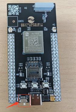
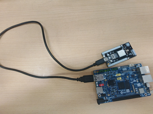
This module is connected via a USB-A to Type-C adapter cable, which means the module is powered through USB. Therefore, make sure to toggle the switch on the 4G development board to the “ON” position;
The default logic level of Air780EPT is 1.8V. If you need to modify the level to 3.3V, connect PIN100: IO_Volt_Set to ground via a Dupont wire (Note: Connecting PIN100: IO_Volt_Set to ground must be completed before powering on the device to take effect);
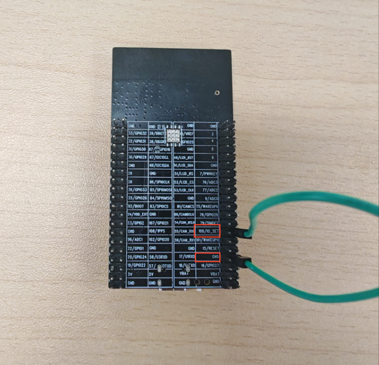
Connection method for wake-up pins:
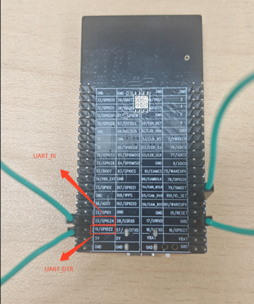
Air780EPT Development Board: PIN19 (UART_DTR) is commonly used as the pin for the external SOC to wake the module from sleep state; PIN20 (UART_RI) is commonly used as the pin for the 4G module to wake the external SOC from sleep state.
OK1126Bx-C Development Board: Pin header P18_13: GPIO7_A0 is the signal for the SOC to wake the module; Pin header P18_16 is the signal for the module to wake the SOC.
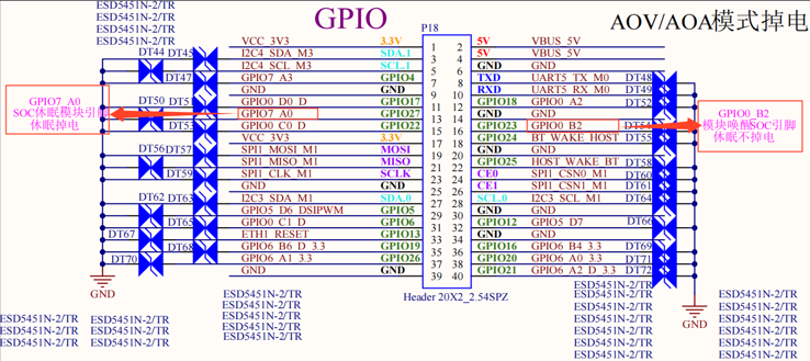
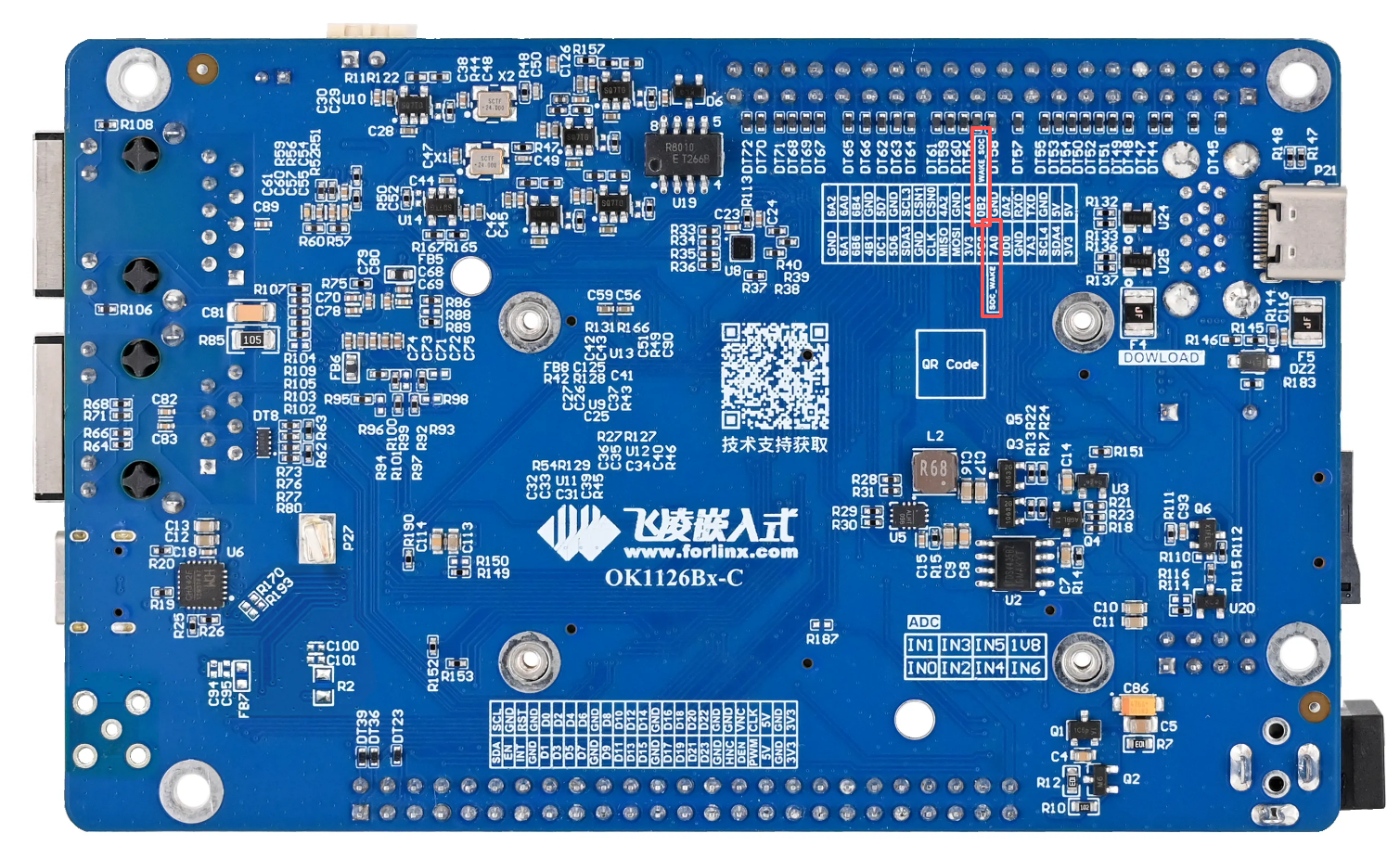
Connect the module’s PIN19 (UART_DTR) pin to P18_13 pin header: This realizes the function of the external SOC waking the module from sleep state;
Connect the module’s PIN20(UART_RI)pin to P18_16 pin header: This realizes the function of the external SOC waking the module from sleep state;
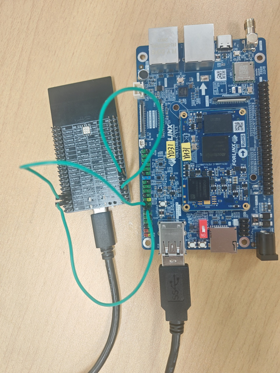
For the 4G module to wake up the CPU, you can directly connect to the existing wake-up pin, GPIO0_A2 (available at the P18_12 header). This pin is already configured for wake-up via a button on the baseboard. If you wish to use pin P18_16 instead, you must modify the device tree to add it as a wake-up source, as shown below:
Open sysdrv/source/kernel/arch/arm64/boot/dts/rockchip/OK1126B-C-common.dtsi
Add the following content to gpio-keys:
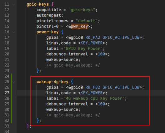
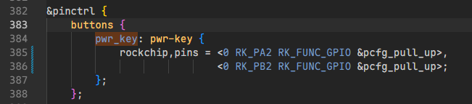
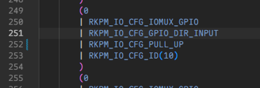
Open sysdrv/source/kernel/arch/arm64/boot/dts/rockchip/FET1126B-C.dtsi
Change the sleep-state configuration of GPIO0_B2 to pull-up:
4.4.3 Test Method
Open VBUS:
echo 23 > /sys/class/gpio/export
echo out > /sys/class/gpio/gpio23/direction
echo 1 > /sys/class/gpio/gpio23/value
Press and hold the power button on the 4G module until the red SYS light turns on and the blue NET light begins to flash.
Driver loading:
cd /oem/usr/ko

insmod mii.ko
insmod usbnet.ko
insmod cdc_ether.ko
insmod rndis_host.ko
Verify whether the driver loaded successfully:
ls /dev/ttyUSB*
If the output includes a device node, it indicates that the driver has been successfully loaded.
Network Configuration
Automatically obtain an IP address via DHCP:
udhcpc -i eth0
If the output resembles the following, DHCP has been configured successful:
udhcpc: started, v1.36.1
udhcpc: broadcasting discover
udhcpc: broadcasting select for 192.168.10.2, server 192.168.10.1
udhcpc: lease of 192.168.10.2 obtained from 192.168.10.1, lease time 86400
deleting routers
adding dns 192.168.10.3
adding dns 192.168.10.4
Once DHCP is successful, you must record the following parameters to facilitate quick network restoration after waking from sleep mode:
IP address, subnet mask, gateway, and DNS.
After a successful DHCP setup, you can test network connectivity using the ping command.
ping www.baidu.com
If udhcpc fails, check whether the RNDIS function is enabled on the 4G module:
Locate the precompiled `sendat` tool (found under `Software Resources\2-Images and Source Code\Test Programs\4G`), copy it to the `/userdata` directory on the development board (e.g., via an SD/TF card), and then execute the following command to access the AT command interface.
cd /userdata/
chmod +x sendat
./sendat /dev/ttyUSB5
Note: The sendat program has no display, and the input content will not be displayed on the terminal. It is recommended to paste only one command each time and press Enter to avoid input errors.
Check RDNIS status:
AT+RNDISCALL?
Return+RNDISCALL: 1 indicates that the RNDIS function is already enabled; you may skip the steps below for enabling the RNDIS function;
Return+RNDISCALL: 0 indicates that the RNDIS function is not enabled. Please follow the steps below to enable the RNDIS function:
AT+RNDISCALL=1
Note: You must restart the 4G module after enabling RNDIS; otherwise, the feature will not take effect.
Sleep/Wake-Keep-Alive Test:
Note: All AT-starting commands are executed under the AT command interaction mode entered via sendat.
Enable the low-power mode of the 4G module:
AT+POWERMODE="PRO"
In this mode, the module enters the low-power state and exits this state upon receiving messages from the server.
Connect to the remote server
AT+CIPSTART="TCP",<Server IP>,<Port number>
The server IP and port number must be those of a real public TCP server. You can use a network debugging tool (such as NetAssist) and an intranet penetration tool locally to map the server to the public network for testing. Assuming the server IP is 111.222.333.444 and the port number is 55555, the connection command is as follows:
AT+CIPSTART="TCP",111.222.333.444,55555
Set the heartbeat period:
AT^HEARTCONFIG=1,0,300
This command enables the heartbeat function with a 300-second interval. For specific parameters, please refer to the official AT command documentation of LuatOS.
Set the heartbeat content:
AT^HEARTBEATHEX=0,6,414243444546
Enable RI wake-up prompt:
AT+CFGRI=1
Function Description: After enabling this function, when the 4G module receives a message from the connected server, it will pull the pin low for 120ms to wake up the main controller
At this point, the 4G module is ready, and you can see on the server side that the client end has connected and is sending packets at regular intervals. The operations of the main controller (OK1126B-C development board) are described as follows:
Main controller sleep:
# Step 1: Clear the timer count
io -4 0x20834310 0

# Step 2: Uninstall the USB module
echo "21480000.usb" > /sys/bus/platform/drivers/ehci-platform/unbind

# Step 3: Enter hibernation mode
echo mem > /sys/power/state
4G module wakes up the main controller:
Currently, the 4G module is in low-power mode. Sending any data from the server to the 4G module will wake up the 4G module, and meanwhile the 4G module will wake up the main controller via the UART_RI pin.
Operations after the main controller wakes up:
Re-mount the USB module:
echo "21480000.usb" > /sys/bus/platform/drivers/ehci-platform/bind
Quickly restore network configuration:
Set the IP address, subnet mask, gateway and DNS according to the previously saved network parameters, or use DHCP to re-obtain network parameters to reconnect to the network. You can perform a ping test again for verification.
ping www.baidu.com
4G module exits low-power mode (AT command interaction mode must be entered first)
AT+POWERMODE="CLOSE"
5. OK1126B-C Multimedia Test
5.1 Camera Test
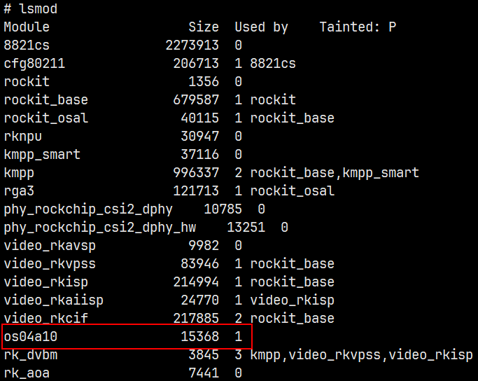
Camera OS04A10
Check the loading status of the camera driver module
lsmod
The results are as follows:
View video devices
v4l2-ctl --list-devices
The results are as follows:
rkaiisp (platform: rkaiisp):
	/dev/video22

rkisp-statistics (platform: rkisp):
	/dev/video28
	/dev/video29

rkcif (platform:rkcif-mipi-lvds):
	/dev/video0
	/dev/video1
	/dev/video2
	/dev/video3
	/dev/video4
	/dev/video5
	/dev/video6
	/dev/video7
	/dev/video8
	/dev/video9
	/dev/video10

rkisp_mainpath (platform:rkisp-vir0):
	/dev/video23
	/dev/video24
	/dev/video25
	/dev/video26
	/dev/video27
	/dev/video30

rkvpss_scale0 (platform:rkvpss-vir0):
	/dev/video32
	/dev/video33
	/dev/video34
	/dev/video35
	/dev/video36
	/dev/video37
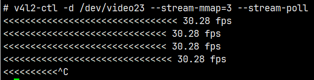
Here, /dev/video23 is the ISP output channel. Run the following command to test whether the video stream can be captured normally, and the result is as follows.
v4l2-ctl -d /dev/video23 --stream-mmap=3 --stream-poll
The results are as follows:
6. Flashing the System
6.1 Image Flashing
6.1.1 Full Flashing
Open the Rockchip Development Tool v3.37 (RKDevTool_v3.37).
Connect the PC to the flashing port of the development board via a Type-C cable.
Press and hold the UPDATE key on the development board, then power on the board. Wait until “Found MASKROM device” is displayed at the bottom of the Rockchip Development Tool, then release the UPDATE key.
Select the firmware upgrade tab, click the firmware button to choose the `update.img` file, and then click the upgrade button to begin the flashing process; the development board will automatically restart once the flashing is complete.