Linux6.1.14_User’s Manual_V1.0
Document classification: □ Top secret □ Secret □ Internal information ■ Open
Copyright
The copyright of this manual belongs to Baoding Folinx Embedded Technology Co., Ltd. Without the written permission of our company, no organizations or individuals have the right to copy, distribute, or reproduce any part of this manual in any form, and violators will be held legally responsible.
Forlinx adheres to copyrights of all graphics and texts used in all publications in original or license-free forms.
The drivers and utilities used for the components are subject to the copyrights of the respective manufacturers. The license conditions of the respective manufacturer are to be adhered to. Related license expenses for the operating system and applications should be calculated/declared separately by the related party or its representatives.
Overview
This manual is designed to help you quickly familiarize yourselves with the product, understand interface functions, and learn testing methods. It primarily covers the testing of development board interface functions, methods for flashing the image, and troubleshooting common issues encountered during use. During testing, certain commands have been annotated for better understanding, focusing on practicality and adequacy. For kernel compilation, related application compilation methods, and development environment setup, please refer to the “User’s Compilation Manual” provided by Forlinx…
There are six chapters:
Chapter 1. briefly introduces the development board’s interface resources, relevant driver paths in the kernel source code, supported flashing and boot methods, and key points in the documentation;
Chapter 2. describes two login methods: serial port login and network login;
Chapter 3. covers the testing of desktop and QT interface functions;
Chapter 4. explains how to perform functional tests using command line operations;
Chapter 5. includes camera playback tests and video hardware encoding/decoding tests;
Chapter 6. details methods for updating the image to storage devices, allowing you to choose the appropriate flashing method based on your actual needs.
Application Scope
The OK1126B-C board ships with a pre-installed Linux image. Before use, verify the system is Linux. If not, re-flash the Linux image following the “Flashing the System” guide. After flashing, use the “Serial Port Login” steps to check the kernel version.
For detailed information, please refer to the OK1126B-C User Materials. All file paths for user materials mentioned in this document are relative to the root directory of the OK1126B-C User Materials.
Revision History
Date |
Version |
SoM Version |
Carrier Board Version |
Revision History |
|---|---|---|---|---|
22/07/2026 |
V1.0 |
V1.1 |
V1.1 |
User’s Manual Initial Version |
1. OK1126B-C Development Board Description
1.1 OK1126B-C/OK1126BJ-C Development Board Description
The OK1126B-C/OK1126BJ-C is a low-power, high-performance processor based on the ARM64 architecture. It integrates a quad-core Cortex-A53 CPU, along with NEON, FPU, NPU, and MCU units, offering NPU computing power up to 3.0 TOPS. It is suitable for AI applications such as intelligent vision.
Connection method: Board to board. The main interfaces are shown in the figure below:
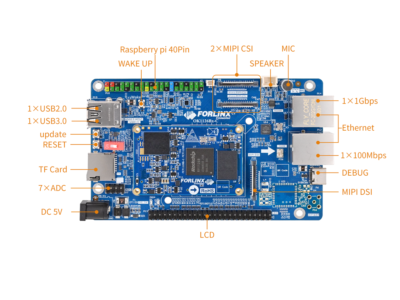
Front
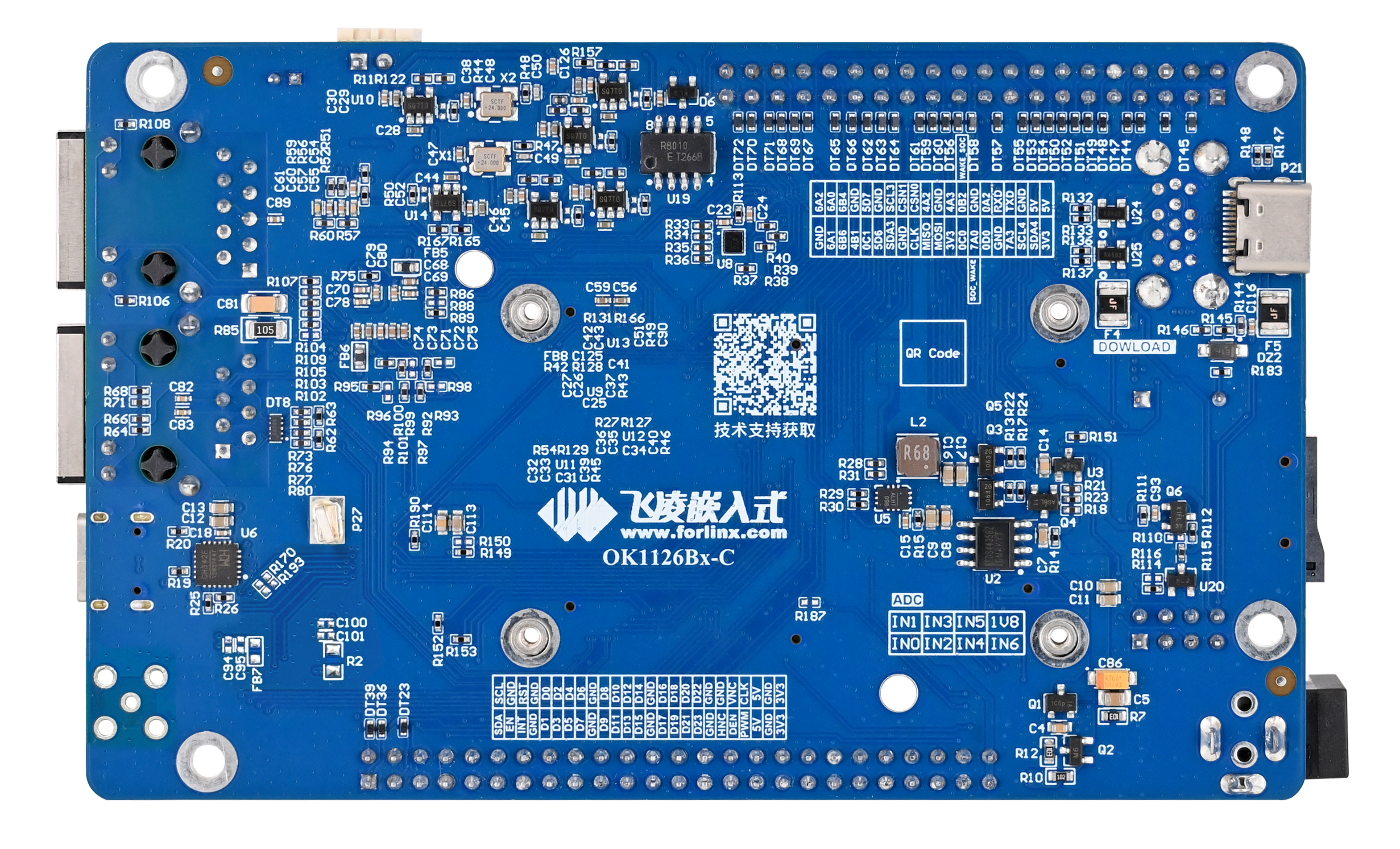
Back
Note:
Hardware parameters are not discussed further in this software manual. Before proceeding with software development based on this manual, please read the “OK1126B-C/OK1126BJ-C Hardware Manual” located in the “Hardware Resources\User Manual” directory. This will help you understand the product naming conventions and the hardware configuration of the unit you are using, thereby facilitating your effective use of this product.
1.2 Linux 6.1.141 System Software Resources
Device |
Driver Source Code Location in the Kernel |
Device Name |
|---|---|---|
LCD Backlight Driver |
drivers/video/backlight/pwm_bl.c |
/sys/class/backlight |
USB Interface: |
drivers/usb/storage/ |
|
USB Mouse |
drivers/hid/usbhid/ |
/dev/input/mice |
Ethernet |
drivers/net/ethernet/stmicro/stmmac |
|
SD/micro TF card driver |
drivers/mmc/host/dw_mmc-rockchip.c |
/dev/block/mmcblk1pX |
EMMC Driver |
drivers/mmc/host/dw_mmc-rockchip.c |
/dev/block/mmcblk2pX |
OS04A10 |
drivers/media/i2c/os04a10.c |
/dev/videoX |
LCD controller |
drivers/gpu/drm/rockchip/rockchip_drm_vop.c |
|
MIPI CSI |
drivers/phy/rockchip/phy-rockchip-mipi-rx.c |
|
MIPI DSI |
drivers/phy/rockchip/phy-rockchip-inno-mipi-dphy.c |
|
LCD touch driver |
drivers/input/touchscreen/gt9xx/* drivers/input/touchscreen/edt-ft5x06.c |
/dev/input/eventX |
RTC Real - Time Clock |
drivers/rtc/rtc-rx8010.c drivers/rtc/rtc-pcf8563.c |
/dev/rtc0 |
Serial Port |
drivers/tty/serial/8250/8250_dw.c |
/dev/ttySX |
LED |
drivers/leds/leds-gpio.c |
|
I2S |
sound/soc/rockchip/rockchip_i2s.c |
|
Audio Driver |
sound/soc/codecs/rk3506_codec.c |
/dev/snd/ |
Watchdog |
drivers/watchdog/dw_wdt.c |
|
SPI |
drivers/spi/spi-rockchip.c |
1.3 eMMC Storage Partition Table
The table below details the eMMC storage partition information for the Linux operating system (The size of a block is 512 bits when calculating.):
Partition Index |
Name |
Offset/Block |
Size/Block |
Content |
|---|---|---|---|---|
N/A |
loader |
0x00000000 |
0x00003fc0 |
MiniLoaderAll.bin |
1 |
uboot |
0x00004000 |
0x00002000 |
uboot.img |
2 |
env |
0x00006000 |
0x00002000 |
env.img |
3 |
misc |
0x00008000 |
0x00002000 |
misc.img |
4 |
boot |
0x0000a000 |
0x00020000 |
boot.img |
5 |
recovery |
0x0002a000 |
0x00040000 |
recovery.img |
6 |
backup |
0x0006a000 |
0x00010000 |
|
7 |
userdata |
0x0007a000 |
0x00400000 |
userdata.img |
8 |
rootfs |
0x0047a000 |
Remaining Space |
rootfs.img |
Use the fdisk -l command on the development board to see the partition size:
root@OK1126B-buildroot:/# fdisk –l
Found valid GPT with protective MBR; using GPT

Disk /dev/mmcblk0: 122224640 sectors, 2336M
Logical sector size: 512
Disk identifier (GUID): 49190000-0000-446d-8000-6a5100000958
Partition table holds up to 128 entries
First usable sector is 34, last usable sector is 122224606

Number  Start (sector)    End (sector)  Size Name
     1           16384           24575 4096K uboot
     2           24576           32767 4096K env
     3           32768           40959 4096K misc
     4           40960          172031 64.0M boot
     5          172032          434175  128M recovery
     6          434176          499711 32.0M backup
     7          499712         4694015 2048M userdata
     8         4694016       122224606 56.0G rootfs
Disk /dev/mmcblk0boot0: 4 MB, 4194304 bytes, 8192 sectors
128 cylinders, 4 heads, 16 sectors/track
Units: sectors of 1 * 512 = 512 bytes

Disk /dev/mmcblk0boot0 doesn't contain a valid partition table
Disk /dev/mmcblk0boot1: 4 MB, 4194304 bytes, 8192 sectors
128 cylinders, 4 heads, 16 sectors/track
Units: sectors of 1 * 512 = 512 bytes

Disk /dev/mmcblk0boot1 doesn't contain a valid partition table
2. Fast Startup
2.1 Preparation Before Startup
5V2A DC Power Cable
Debug port cable

2.2 Debugging Serial Port Driver Installation
OK1126B-C/ The OK1126BJ-C platform features a Type-C port for serial debugging and an onboard USB-to-UART chip. No additional USB-to-serial debugging tool is required, making the setup simple and convenient.
To install the driver, please use the driver package CH343SER.EXE provided in the \” Table of Contents Tools directory of the software materials.
2.3 Serial Port Login
2.3.1 Serial Connection Settings
Note:
The serial terminal supports password-free login;
Settings: Baud rate 115200, 8 data bits, 1 stop bit, no parity/flow control;
Hardware Requirements: Type-C for connecting PC and development board;
Software Requirements:
A serial terminal application must be installed on the PC Windows. There are various terminal programs available, and you may choose any one you are familiar with.
Take putty as an example to introduce the setting mode of the putty terminal:
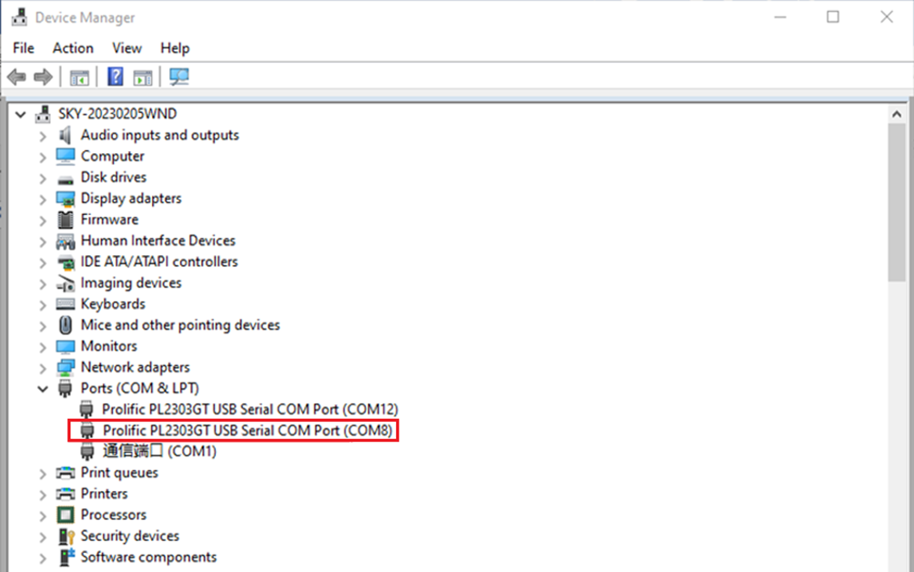
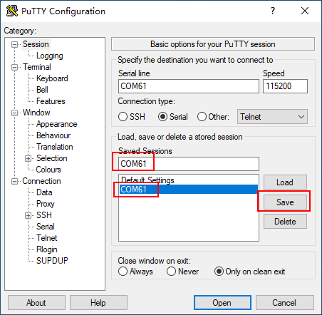
Step1: Identify the serial port number assigned to the PC. In Device Manager, locate the serial port with the name ending in “SERIAL-”, which corresponds to the actual debug UART. For example, this may appear as COM61; the port number should be based on the actual one detected by the system.
Step2: Open the putty and set the serial line according to the com port of the computer used. The baud rate is 115200.
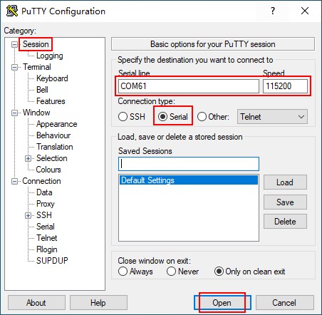
Step 3: After completing the above settings, enter the COM port number used by your computer in the “Saved Sessions” field (as shown in the following figure, using COM61 as an example), and save the configuration. Subsequently, when reopening the serial port, simply click the saved port number to directly apply the settings.
2.3.2 Serial Port Login
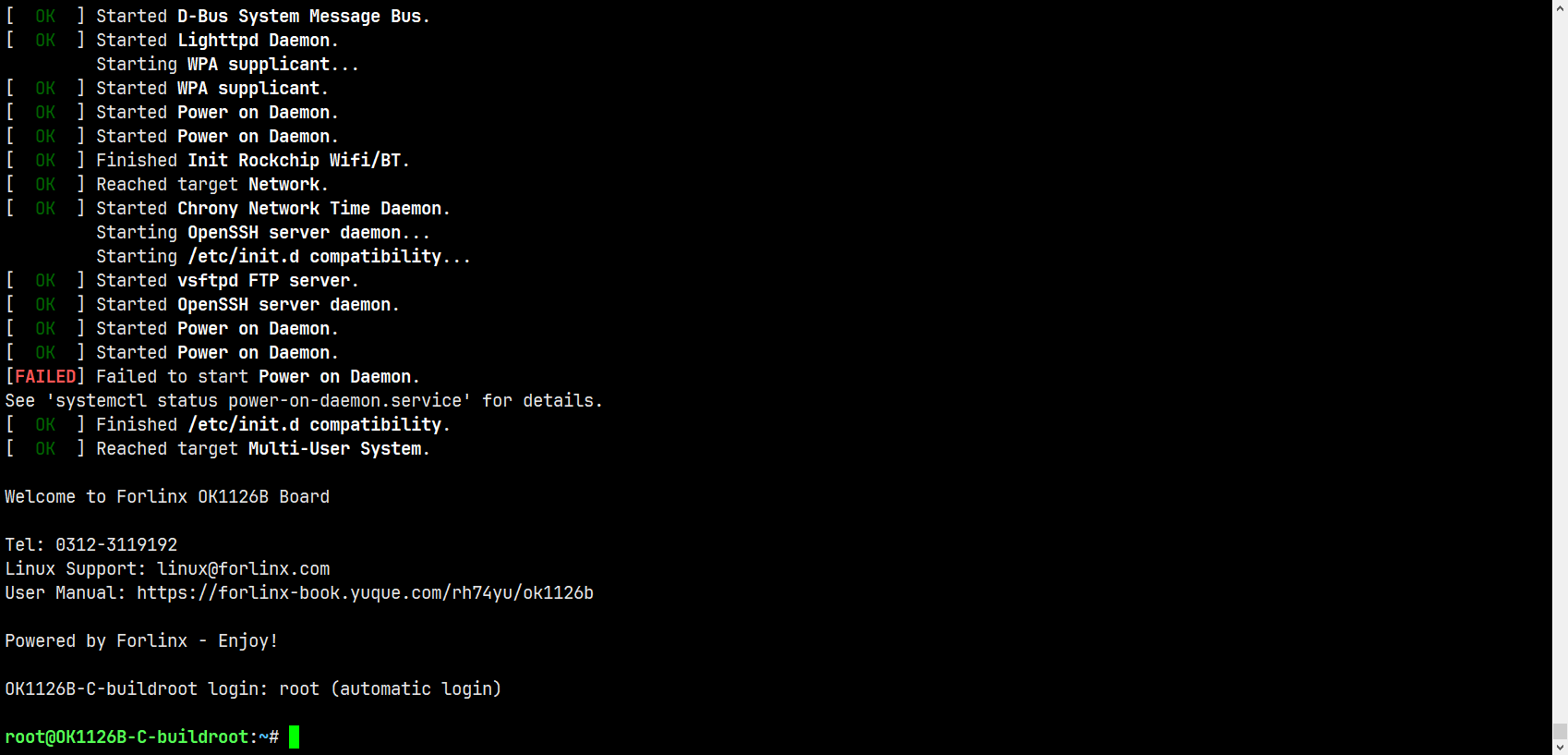
After the PC terminal software is configured, connect the PC and the development board using a serial cable, then power on the device after connecting the power supply. The startup information can be viewed through the terminal software.
The following startup message indicates a successful boot, and you can press Enter to create a new command line:
2.4 Network Login
OK1126B-C/ In addition to using the debug UART for login, the OK1126BJ-C supports SSH network login to the development board, as well as SFTP file transfer.. Take the development board IP 172.20.0.129 as an example to introduce the network tool. The network IP can be modified through ifconfig eth0 172.20.0.129, and then the development board and the PC are connected to the same switch or directly connected through the network cable.
2.4.1 SSH
OK1126B-C/ The OK1126BJ-C development board supports SSH services, which are enabled automatically upon startup. Once the IP address is configured, the board can be used as an SSH server. You can use SSH to log in to the development board for development and debugging, and you can also use SCP for file transfer.
Note:
When logging in, enter the username “root” and no password;
The following tests were carried out using the development board’s IP address 172.20.0.129. Please modify it according to the actual situation. Use the following command in the serial debugging terminal to change the settings.
ifconfig eth0 172.20.0.129 netmask 255.255.255.0
You can log in using the ssh command via the Ubuntu terminal.
forlinx@ubuntu:~$ ssh [email protected]
The authenticity of host '172.20.0.129 (172.20.0.129)' can't be established.
ECDSA key fingerprint is SHA256:Ck2/mikcGI8BlJgfx7npSJdQmkgIW+yfj/uiJq+xG/I.

Are you sure you want to continue connecting (yes/no/[fingerprint])? yes
Warning: Permanently added '172.20.0.129' (ECDSA) to the list of known hosts.
root@OK1126B-C-buildroot:~#
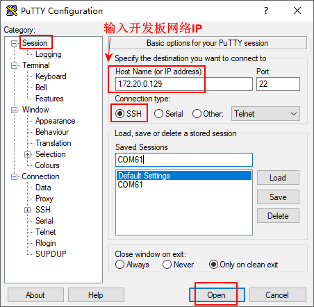
You can also use other terminal programmes that support SSH logins, such as PuTTY. The setup procedure is as follows:
Open the PuTTY software and configure the following settings (please use your actual IP address):
2.4.2 FTP
OK1126B-C/ The OK1126BJ-C development board supports FTP services, which are enabled automatically upon startup. Once the IP address is configured, the board can be used as an FTP server. The following describes how to utilize the FTP tool for file transfer.
Path: OK1126B-C/ OK1126BJ-C (Linux) User Data\Tools\*
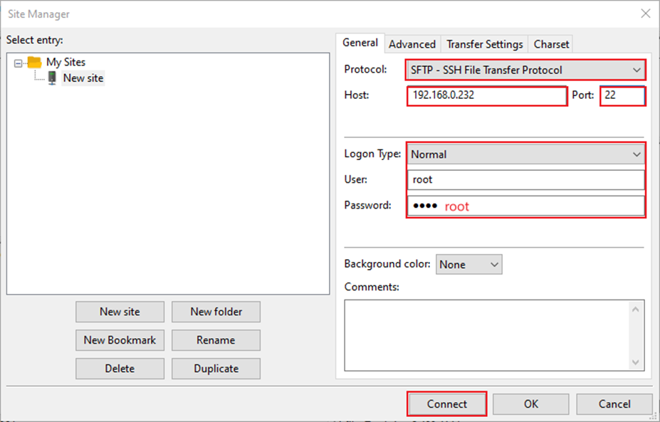
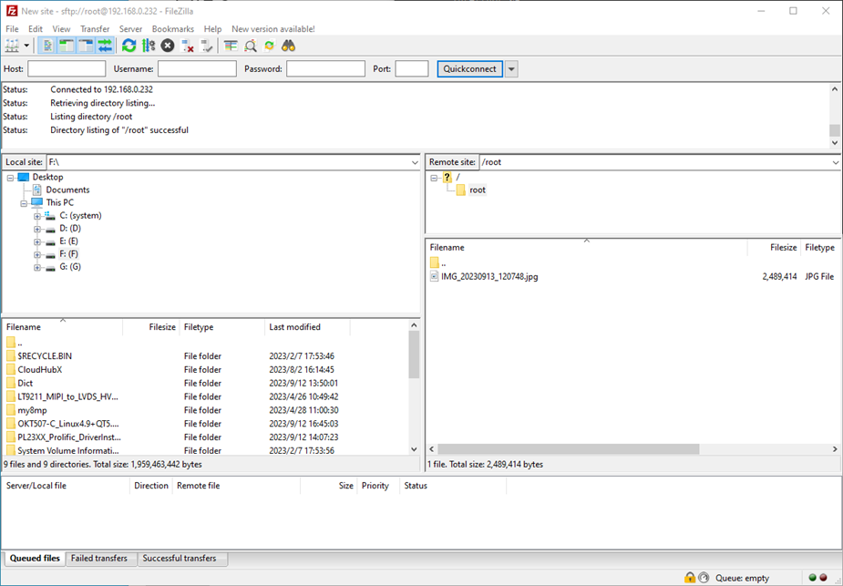
Install FileZilla tool on Windows and follow the steps shown in the figure below to set it up.
Note: To use this function, please connect an Ethernet cable to the development board. Ensure that the host IP is configured in the same subnet as the client’s, guaranteeing both are on the same local area network. Use the credentials username: forlinx, password: forlinx to log in. Once logged in, you can upload, download, or delete files in the /home/forlinx/ directory of the filesystem.
The following test uses the development board IP 172.20.0.129. Please modify it according to your actual network setup. You can change the IP in the debug serial terminal using the following command:
ifconfig eth0 172.20.0.129 netmask 255.255.255.0
2.5 Screen Switch
The OK1126B-C/OK1126BJ-C supports two types of display interfaces: LCD and MIPI DSI. Currently, the display switching can be controlled in two ways: 1. Dynamic control via the U-Boot menu; 2. Static control specified in the kernel device tree.
2.5.2 Kernel Device Tree Specification
This method does not require a serial terminal connection. The system image is configured with the default desired settings, making it suitable for mass production. However, manual modification of the device tree is required, followed by regeneration of the system image.
Note: This method takes precedence over the U-Boot screen selection. After modifying the device tree, the U-Boot screen selection will no longer be effective.
The device tree path is: kernel/arch/arm64/boot/dts/rockchip/OK1126B-C-common.dtsi.
In the kernel source code, open the device DTSI file and locate the following node:
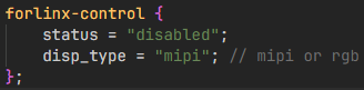
The node is disabled by default and needs to be changed to “okay” to enable it. Modify according to the screen requirements.
For example:
Turn on the RGB screen and change the property to “rgb”.
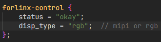
After saving, recompile to generate the image.
For MIPI screens, there are many types, and the existing timing and control words may not meet the requirements. You may need to manually modify the display-timings under the DSI node. However, any display-related node’s status property should be handled as per the default settings, as the program will automatically control it.
2.6 System Shutdown
In general, you can directly power off the system. However, if operations such as data storage or functional usage are in progress, avoid cutting power abruptly to prevent irreversible file damage, which may require re-flashing the firmware. To ensure all data is fully written, you can execute the sync command to complete data synchronization before powering off.
Note: For products based on the SoM design, if unexpected power loss occurs during use, leading to system shutdown issues, power loss protection measures can be incorporated into the design.
3. OK1126B-C QT Function Testing
This section requires a screen to follow the instructions; users without a display may skip this section. Forlinx has made numerous optimisations to the interface functionality and provides a wide range of test programs for reference. However, due to limitations, users are advised not to use Forlinx test programs directly when developing their own products; instead, they are encouraged to write their own applications.
The OK1126B-C/OK1126BJ-C platform supports QT 5.15.11 and comes pre-installed with several QT demo applications for testing.
Before starting your tests, please configure the display via the U-Boot menu.
Note: For applications that cannot launch the on-screen keyboard, you may connect a physical keyboard for input.
After booting, the system will automatically enter the desktop as shown in the figure below:

3.1 4G Test
The test supports the 4G module (EM05). Insert the 4G module and SIM card in case of power failure.
Click the desktop icon to access the program:

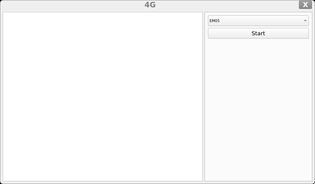
Click the start button, and the program will automatically enter the dial-up process and obtain IP, set DNS, etc.
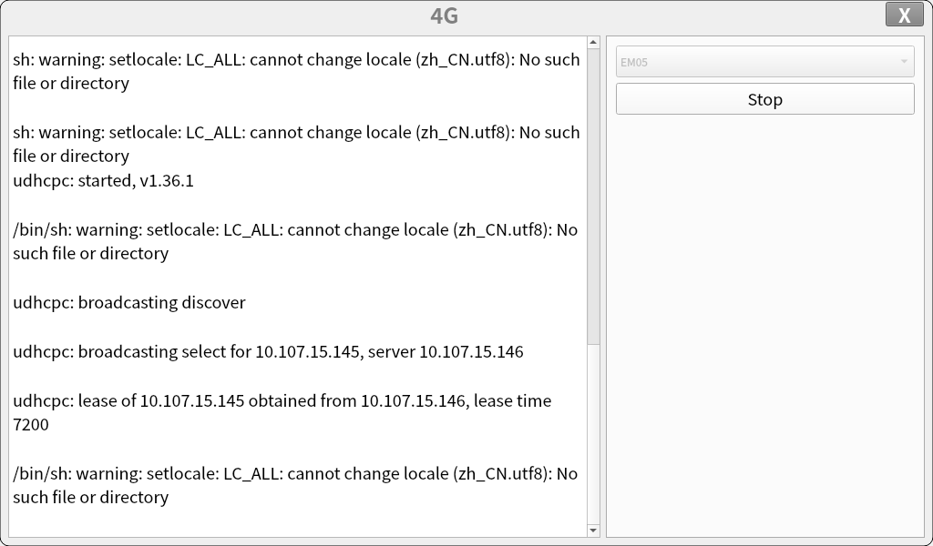
After successful dialing, you can use ping to test the debugging serial port.
3.2 Network Configuration Test
Click the desktop icon to access the program:

DHCP mode interface is as follows:
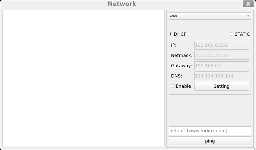
Select DHCP, choose the network card device to be configured in the “interface” section, and click “Apply and Restart Network” at the bottom of the interface to automatically restart the network and obtain an IP address.
STATIC mode interface is as follows:
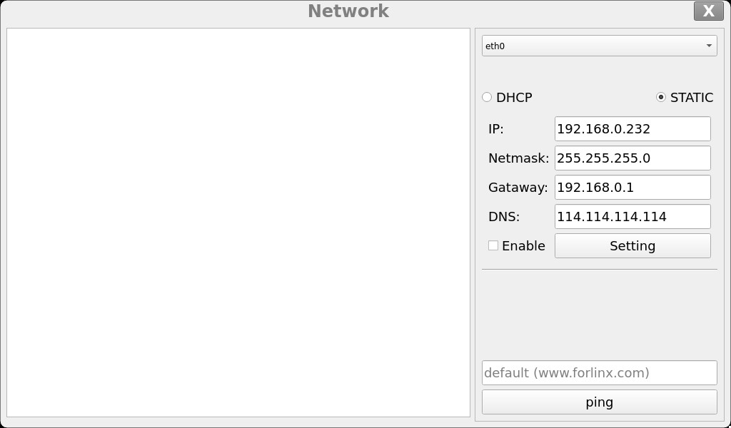
Select the network card device to be configured in the Interface. Enter the desired IP address in the IP field. Enter the subnet mask in the Netmask field. Enter the gateway address in the Gateway field. Enter the DNS server address , in the Gateway field, .
Note: The IP and other information configured in static mode will be saved in the system’s relevant configuration files, so the network settings will persist after each reboot. However, the network information configured in DHCP mode does not need to be considered, as an IP address will be dynamically assigned each time the system restarts.
3.3 Ping Test
Click the desktop icon to access the program:

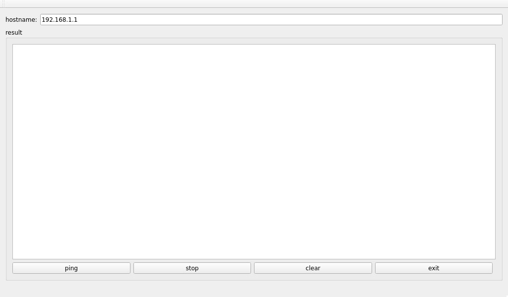
In the hostname field, write the target IP to ping. After clicking the “ping” button, the result field will show the ping result. Click stop to stop the ping test, and click “clear” to clear the information in result.
3.4 Watchdog Test
Click the desktop icon to access the program:

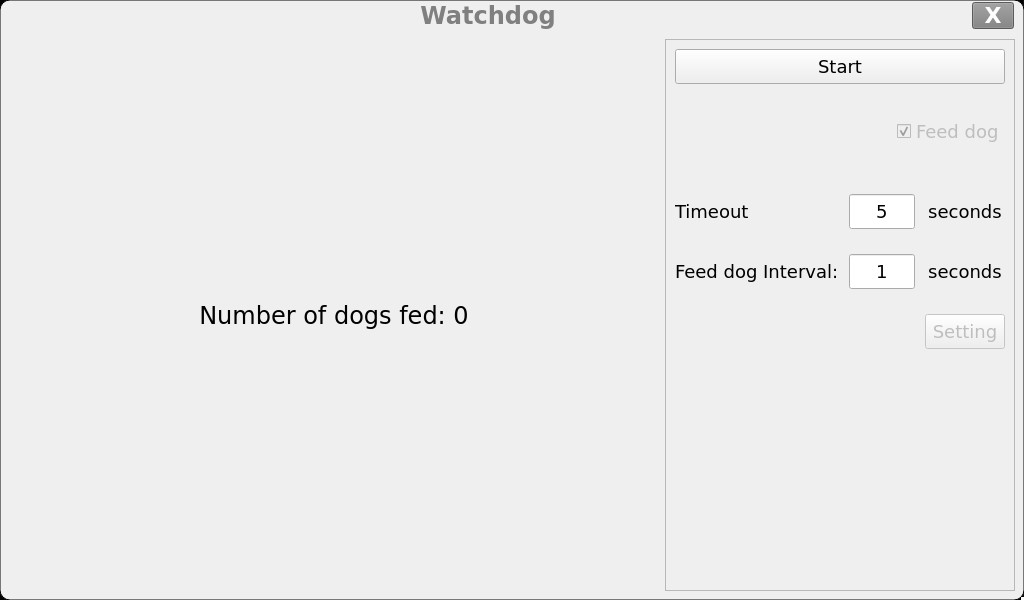
Click the “Start” button and tick the “Feed dog” box; the watchdog function will then be activated and the programme will feed dog. Under normal circumstances, the system will not reboot. When the “Feed dog” box is unticked, the programme will not feed dog, and once the countdown has ended, the system will reboot, indicating that the watchdog function is working correctly.
3.5 RTC Test
Click the desktop icon to access the program:

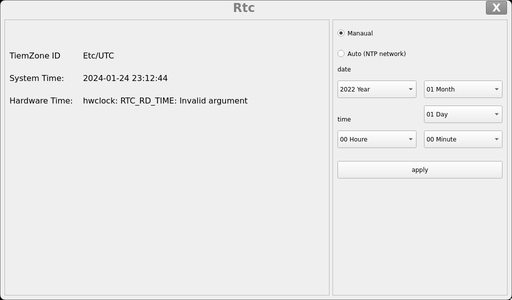
Select the year, month, day, hour, minute and second to set the time. Once you have finished, click “Apply” to complete the setting.
With the RTC backup battery installed, you can reboot the development board to confirm that the RTC clock has been successfully set.
3.6 UART Test
This test is carried out by short-circuiting the TX and RX pins of UART5; please refer to Section 4.5 for the specific wiring configuration.
Click the desktop icon to access the program:

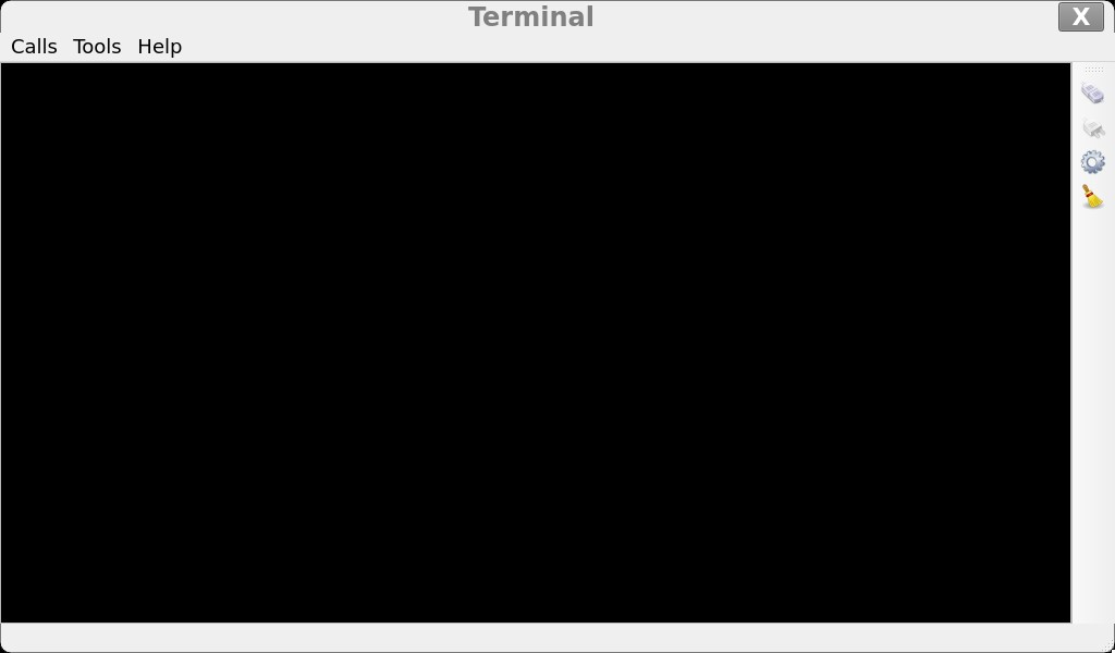
Click the settings button (the third small gear icon) on the right sidebar, and configure the serial port parameters as follows:
Relevant Parameter |
Meaning |
|---|---|
Select Serial Port |
Configure the serial port (select UART5, i.e. ttyS5) |
BaudRate |
Set baud rate (115200) |
Data bits |
Set data bits (8 bits) |
Parity |
Set parity bit (no parity) |
Stop bits |
Set stop bits (1 bit) |
Flow control |
Set flow control (no flow control) |
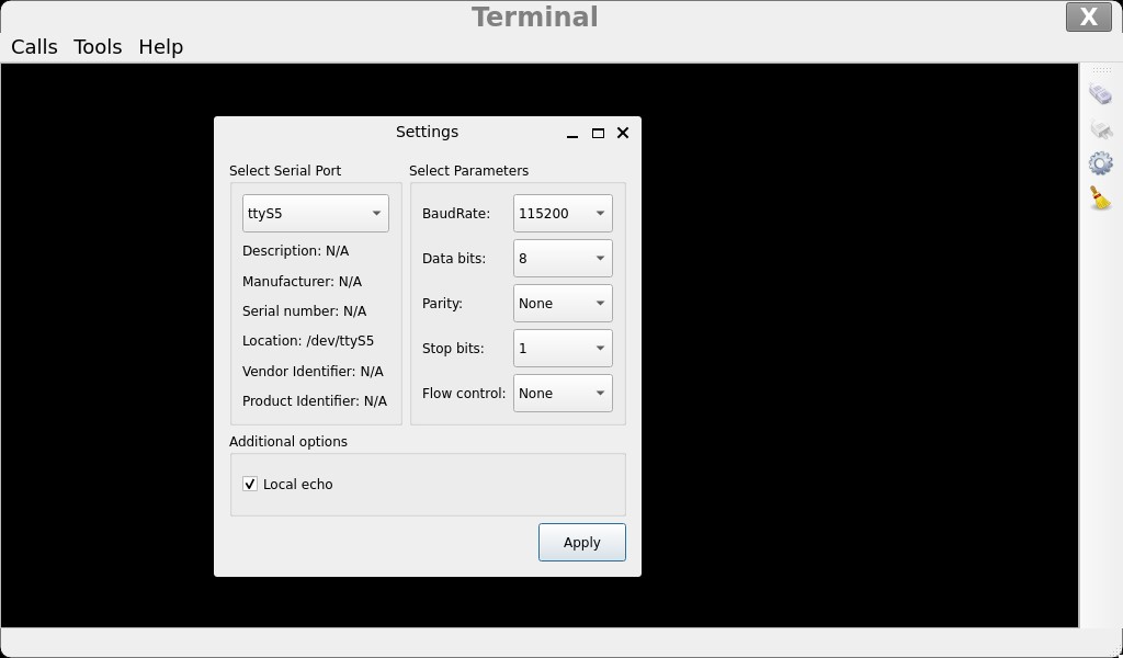
After configuring the serial port parameters, click the connect button at the top of the right sidebar (the first button). At this point, the test program can proceed with data transmission and reception testing.
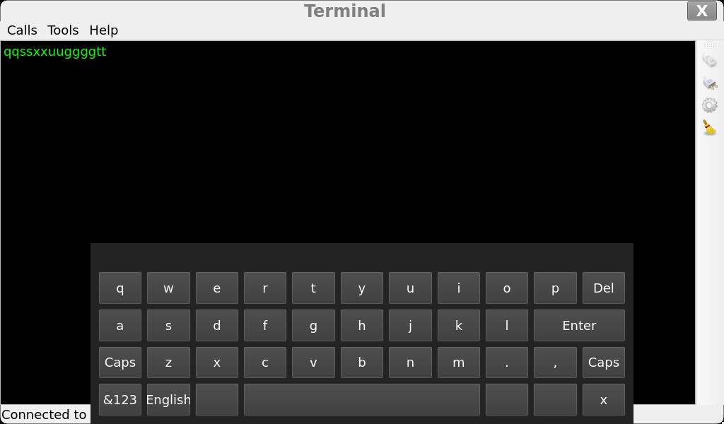
You can enter text in the black area; each character entered will be displayed twice. This is because the TX and RX pins are short-circuited, so the characters sent out are received back.
3.7 Backlight Test
Click the desktop icon to access the program:

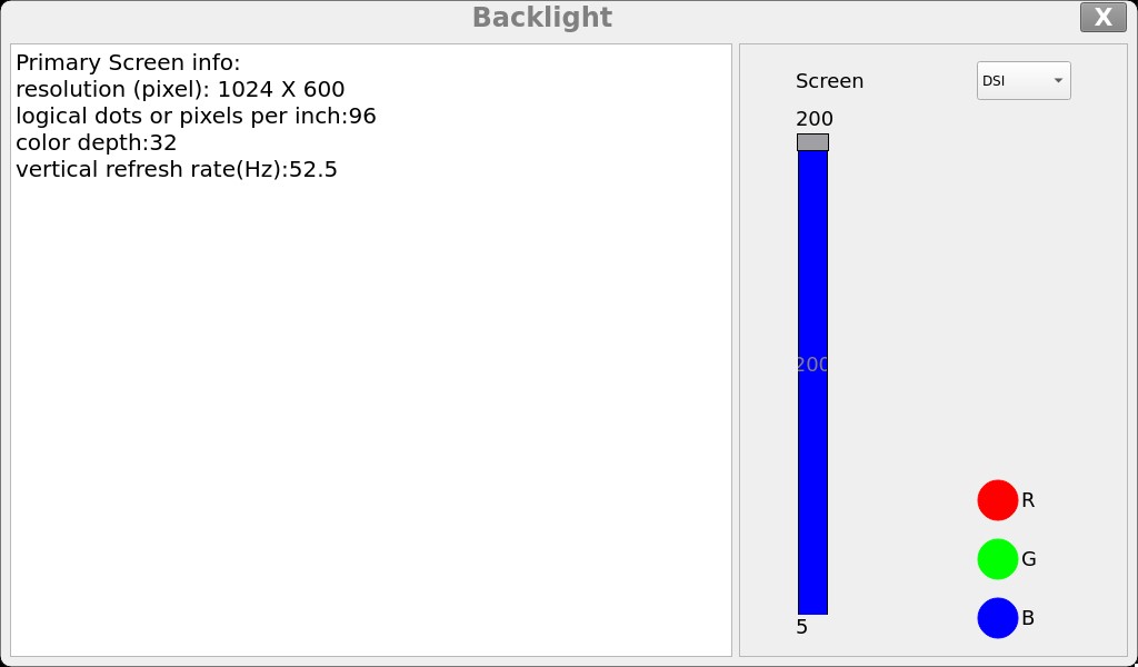
Select “Screen” to specify the screen backlight you wish to adjust, then drag the slider on the interface to set the backlight brightness; level 5 is the lowest brightness and level 200 is the highest.
To turn off the backlight, refer to Section 4.12 (LCD Backlight Adjustment) and set the backlight brightness to 0.
3.8 SPI Test
Click the desktop icon to access the program:

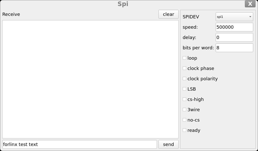
Short-circuit the MOSI and MISO pins of SPI1 (refer to Section 4.6 for the specific wiring).
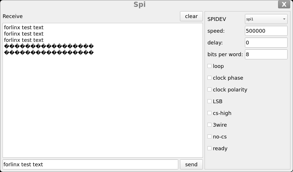
Select SPIDEV as spi1 and click the Send button. The content in the lower input box will be transmitted through MOSI and received back via MISO, displaying in the upper Receive box.
3.9 Audio Playback Test
Click the desktop icon to access the program:

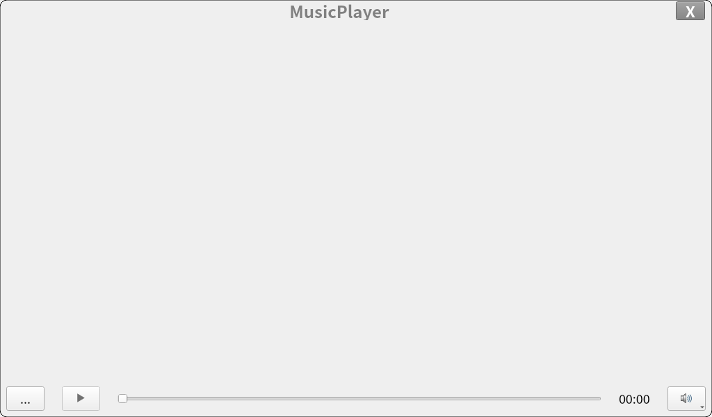
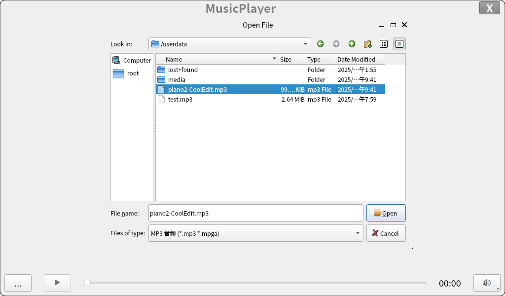
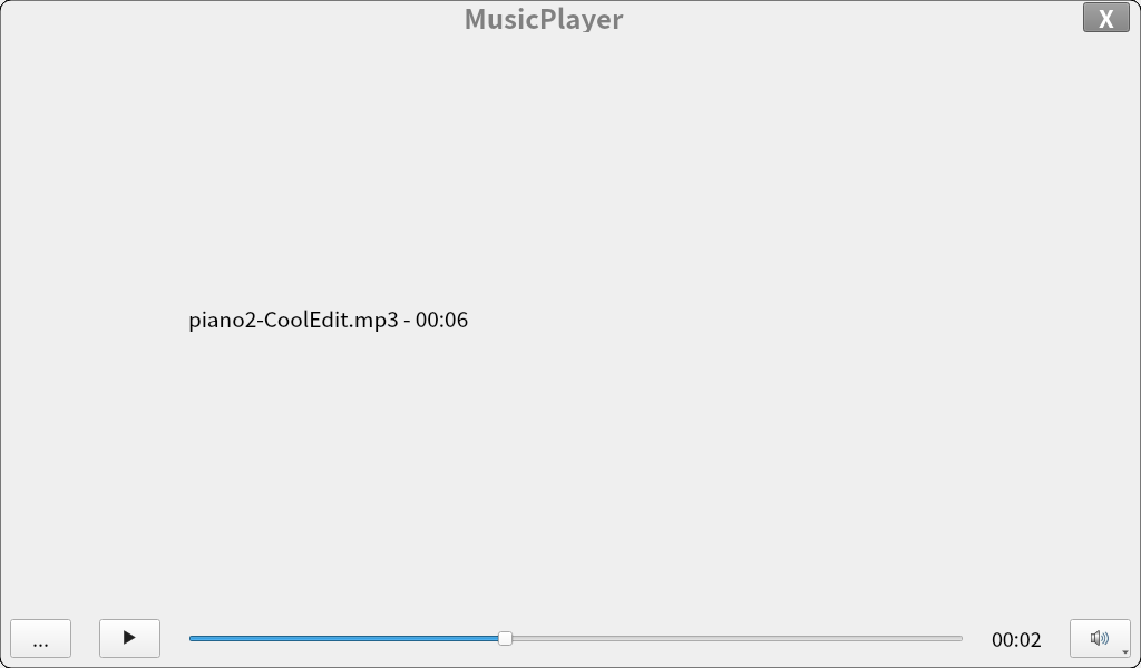
Click the three-dot button in the bottom-left corner to select the audio file you want to play, then click Open. The selected audio will start playing automatically.
3.10 Video Playback Test
Click the desktop icon to access the program:

The video will automatically start playing upon launching the application.

3.11 Recording Test
Click the desktop icon to access the program:

After opening, enter the recording test program.
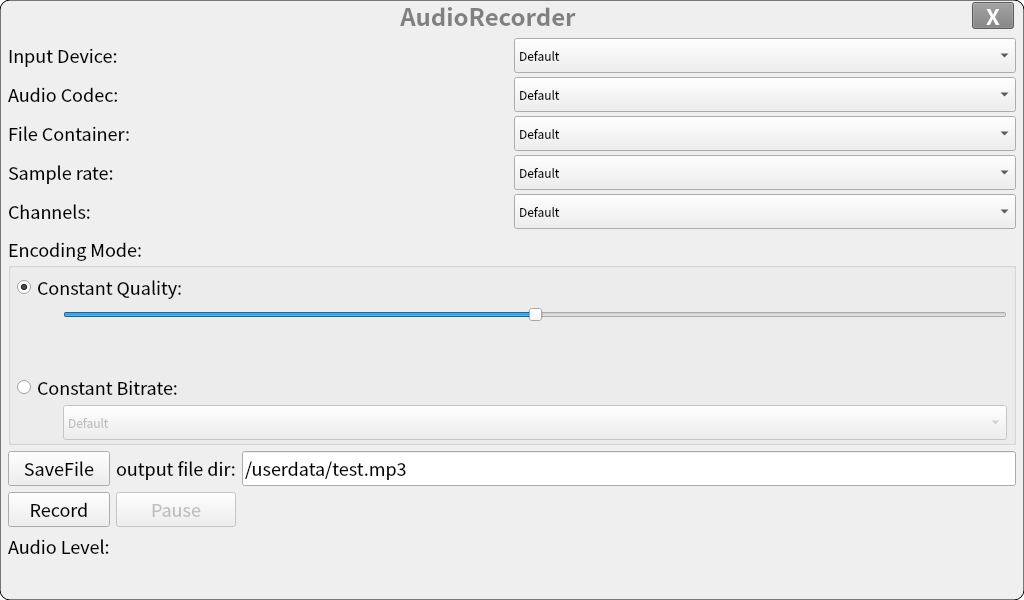
Click “SaveFile” to set the filename of the recording file (which can be modified in the “output file dir” section), and click “Record” to start recording
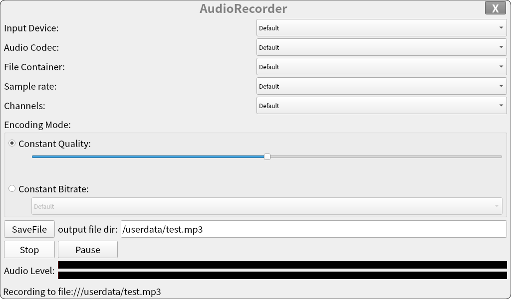
Click “Stop” to end the recording

Finally, you can find the audio file test.mp3 under /userdata/.
4. OK1126B-C Command Function Test
The OK1126B-C/OK1126BJ-C platform comes with a rich set of command-line tools for users to utilize. You can explore the interfaces and features of the development board through command-line programs. However, due to limited functional coverage, it is not recommended to directly use Forlinx test programs for product development. Instead, it is advised to write custom applications based on actual usage scenarios.
4.1 System Information Query
View kernel and CPU information:
root@OK1126B-C-buildroot:/# uname -a
Linux OK1126B-C-buildroot 6.1.141 #1 SMP Wed May  6 19:28:38 MST 2026 aarch64 GNU/Linux
View environment variable information:
root@OK1126B-C-buildroot:/# env
SHELL=/bin/bash
GST_V4L2_PREFERRED_FOURCC=NV12:YU12:NV16:YUY2
GST_VIDEO_CONVERT_PREFERRED_FORMAT=NV12:NV16:I420:YUY2
PLAYBIN2_PREFERRED_VIDEOSINK=kmssink
GST_V4L2_USE_LIBV4L2=1
WESTON_DRM_MIN_BUFFERS=2
WL_OUTPUT_VERSION=3
GST_INSPECT_NO_COLORS=1
EDITOR=/bin/vi
WESTON_DRM_KEEP_RATIO=1
GST_DEBUG_NO_COLOR=1
PWD=/root
LOGNAME=root
WESTON_VNC_MIN_BUFFERS=4
HOME=/root
LANG=en_US.UTF-8
ADB_TCP_PORT=5555
LS_COLORS=rs=0:di=01;34:ln=01;36:mh=00:pi=40;33:so=01;35:do=01;35:bd=40;33;01:cd=40;33;01:or=40;31;01:mi=00:su=37;41:sg=30;43:ca=00:tw=30;42:ow=34;42:st=37;44:ex=01;32:*.tar=01;31:*.tgz=01;31:*.arc=01;31:*.arj=01;31:*.taz=01;31:*.lha=01;31:*.lz4=01;31:*.lzh=01;31:*.lzma=01;31:*.tlz=01;31:*.txz=01;31:*.tzo=01;31:*.t7z=01;31:*.zip=01;31:*.z=01;31:*.dz=01;
31:*.gz=01;31:*.lrz=01;31:*.lz=01;31:*.lzo=01;31:*.xz=01;31:*.zst=01;31:*.tzst=01;
31:*.bz2=01;31:*.bz=01;31:*.tbz=01;31:*.tbz2=01;31:*.tz=01;31:*.deb=01;31:*.rpm=01;31:*.jar=01;31:*.war=01;31:*.ear=01;31:*.sar=01;31:*.rar=01;31:*.alz=01;31:*.ace=01;31:*.zoo=01;31:*.cpio=01;31:*.7z=01;31:*.rz=01;31:*.cab=01;31:*.wim=01;31:*.swm=01;31:*.dwm=01;31:*.esd=01;31:*.avif=01;35:*.jpg=01;35:*.jpeg=01;35:*.mjpg=01;35:*.mjpeg=01;35:*.gif=01;35:*.bmp=01;35:*.pbm=01;35:*.pgm=01;35:*.ppm=01;35:*.tga=01;35:*.xbm=01;35:*.xpm=01;35:*.tif=01;35:*.tiff=01;35:*.png=01;35:*.svg=01;
35:*.svgz=01;35:*.mng=01;35:*.pcx=01;35:*.mov=01;35:*.mpg=01;35:*.mpeg=01;35:*.m2v=01;35:*.mkv=01;35:*.webm=01;35:*.webp=01;35:*.ogm=01;35:*.mp4=01;35:*.m4v=01;35:*.mp4v=01;35:*.vob=01;35:*.qt=01;35:*.nuv=01;35:*.wmv=01;35:*.asf=01;35:*.rm=01;35:*.rmvb=01;35:*.flc=01;35:*.avi=01;35:*.fli=01;35:*.flv=01;35:*.gl=01;35:*.dl=01;35:*.xcf=01;35:*.xwd=01;35:*.yuv=01;35:*.cgm=01;35:*.emf=01;35:*.ogv=01;35:*.ogx=01;35:*.aac=00;36:*.au=00;36:*.flac=00;36:*.m4a=00;36:*.mid=00;36:*.midi=00;36:*.mka=00;36:*.mp3=00;36:*.mpc=00;36:*.ogg=00;36:*.ra=00;36:*.wav=00;36:*.oga=00;36:*.opus=00;36:*.spx=00;36:*.xspf=00;36:*~=00;90:*#=00;90:*.bak=00;90:*.old=00;90:*.orig=00;90:*.part=00;90:*.rej=00;90:*.swp=00;90:*.tmp=00;90:*.dpkg-dist=00;90:*.dpkg-old=00;90:*.ucf-dist=00;90:*.ucf-new=00;90:*.ucf-old=00;90:*.rpmnew=00;90:*.rpmorig=00;90:*.rpmsave=00;90:
WESTON_FREEZE_DISPLAY=/tmp/.freeze_weston
WAYLANDSINK_FORCE_DMABUF=1
GST_V4L2SRC_DEFAULT_DEVICE=/dev/video-camera0
QT_QPA_PLATFORM=wayland
AUTOVIDEOSINK_PREFERRED=kmssink
USB_FW_VERSION=0x0310
TERM=xterm-color
USER=root
ADBD_SHELL=/bin/bash
GST_V4L2SRC_RK_DEVICES=_mainpath:_selfpath:_bypass:_scale
WESTON_DRM_MIRROR=1
SHLVL=1
GST_VIDEO_FLIP_USE_RGA=1
USB_FUNCS=adb
WESTON_DISABLE_ATOMIC=1
USB_MANUFACTURER=Rockchip
USB_PRODUCT=rk3xxx
XDG_RUNTIME_DIR=/var/run
USB_VENDOR_ID=0x2207
GST_VIDEO_CONVERT_USE_RGA=1
PATH=/usr/bin:/usr/sbin
GST_V4L2SRC_MAX_RESOLUTION=3840x2160
GST_VIDEO_DECODER_QOS=0
_=/usr/bin/env
4.2 Frequency Test
Note: This process uses CPU0 as an example. In reality, CPU1, CPU2, and CPU3 will be adjusted simultaneously.
The types of CPU frequency governors supported by the current kernel:
root@OK1126B-C-buildroot:/# cat /sys/devices/system/cpu/cpu0/cpufreq/scaling_available_governors
interactive conservative ondemand userspace powersave performance schedutil
Among these, userspace represents user mode, which allows other user programs to adjust CPU frequency in this mode.
View the frequency scaling levels supported by the current CPU.
Commercial-grade CPU (RV1126B):
root@OK1126B-C-buildroot:/# cat /sys/devices/system/cpu/cpu0/cpufreq/scaling_available_frequencies
594000 816000 1008000 1200000 1296000 1416000 1512000 1608000
Industrial-grade CPU( RV1126BJ):
root@OK1126B-C-buildroot:/# cat /sys/devices/system/cpu/cpu0/cpufreq/scaling_available_frequencies
594000 816000 1008000 1200000 1296000
Set to userspace mode and modify the frequency to 1296000:
root@OK1126B-C-buildroot:/# echo userspace > /sys/devices/system/cpu/cpu0/cpufreq/scaling_governor
root@OK1126B-C-buildroot:/# echo 1296000 > /sys/devices/system/cpu/cpu0/cpufreq/scaling_setspeed
To view the current frequency after modification:
root@OK1126B-C-buildroot:/# cat /sys/devices/system/cpu/cpu0/cpufreq/cpuinfo_cur_freq
1296000
4.3 Temperature Test
To view temperature values:
root@OK1126B-C-buildroot:/# cat /sys/class/thermal/thermal_zone0/temp
41860
The temperature value is 41℃.
4.4 DDR Bandwidth Test
root@OK1126B-C-buildroot:/# memory_bandwidth.sh
L1 cache bandwidth rd test with # process
0.008192 19094.07
0.008192 18813.20
0.008192 18950.10
0.008192 18795.16
0.008192 18822.52
L2 cache bandwidth rd test
0.131072 8361.20
0.131072 8502.86
0.131072 8351.11
0.131072 8337.79
0.131072 8471.48
Main mem bandwidth rd test
52.43 2068.61
52.43 2052.25
52.43 2074.17
52.43 2051.29
52.43 2065.59
L1 cache bandwidth wr test with # process
0.008192 16513.58
0.008192 16513.58
0.008192 16501.58
0.008192 16513.58
0.008192 16510.58
L2 cache bandwidth wr test
0.131072 8914.04
0.131072 9270.83
0.131072 9258.58
0.131072 9202.17
0.131072 9234.96
Main mem bandwidth wr test
52.43 1624.54
52.43 1623.89
52.43 1624.84
52.43 1620.77
52.43 1619.12
L1 cache bandwidth rdwr test with # process
0.008192 8365.76
0.008192 8370.70
0.008192 8364.24
0.008192 8347.94
0.008192 8371.83
L2 cache bandwidth rdwr test
0.131072 6480.13
0.131072 6437.67
0.131072 6448.15
0.131072 6473.90
0.131072 6463.02
Main mem bandwidth rdwr test
52.43 1611.61
52.43 1592.18
52.43 1615.73
52.43 1609.18
52.43 1592.52
L1 cache bandwidth cp test with # process
0.008192 10665.67
0.008192 10655.99
0.008192 10657.61
0.008192 10667.61
0.008192 10665.67
L2 cache bandwidth cp test
0.131072 4053.53
0.131072 3808.85
0.131072 4079.25
0.131072 3822.83
0.131072 4027.15
Main mem bandwidth cp test
52.43 743.06
52.43 743.84
52.43 742.60
52.43 743.23
52.43 743.54
L1 cache bandwidth frd test with # process
0.008192 4270.23
0.008192 4269.05
0.008192 4266.73
0.008192 4269.24
0.008192 4269.05
L2 cache bandwidth frd test
0.131072 3713.35
0.131072 3793.00
0.131072 3774.39
0.131072 3798.15
0.131072 3757.74
Main mem bandwidth frd test
52.43 2052.33
52.43 2034.41
52.43 2037.65
52.43 2036.62
52.43 2000.11
L1 cache bandwidth fwr test with # process
0.008192 14100.84
0.008192 14509.01
0.008192 14594.61
0.008192 14325.57
0.008192 13626.49
L2 cache bandwidth fwr test
0.131072 7851.06
0.131072 7947.65
0.131072 8714.56
0.131072 9114.45
0.131072 8064.78
Main mem bandwidth fwr test
52.43 5930.19
52.43 5954.43
52.43 5892.86
52.43 5909.47
52.43 5952.41
L1 cache bandwidth fcp test with # process
0.008192 2691.91
0.008192 2692.89
0.008192 2692.89
0.008192 2691.61
0.008192 2692.89
L2 cache bandwidth fcp test
0.131072 2573.31
0.131072 2573.78
0.131072 2557.76
0.131072 2579.32
0.131072 2571.92
Main mem bandwidth fcp test
52.43 1340.10
52.43 1325.53
52.43 1348.17
52.43 1345.19
52.43 1327.41
L1 cache bandwidth bzero test with # process
0.008192 5992.52
0.008192 5307.81
0.008192 5965.74
0.008192 5970.87
0.008192 5951.24
L2 cache bandwidth bzero test
0.131072 5908.60
0.131072 5868.90
0.131072 5946.02
0.131072 5956.76
0.131072 5923.45
Main mem bandwidth bzero test
52.43 5978.88
52.43 5919.48
52.43 5928.18
52.43 5951.06
52.43 5947.01
L1 cache bandwidth bcopy test with # process
0.008192 6090.88
0.008192 6086.46
0.008192 6082.05
0.008192 6084.55
0.008192 6081.24
L2 cache bandwidth bcopy test
0.131072 5623.23
0.131072 5608.39
0.131072 5395.44
0.131072 5609.43
0.131072 5634.65
Main mem bandwidth bcopy test
52.43 1296.04
52.43 1257.62
52.43 1234.17
52.43 1261.37
52.43 1280.09
The LPDDR4 write bandwidth of OK1126B-C/OK1126BJ-C is approximately 1600M/s, and the read bandwidth is approximately 2000M/s.
4.5 Serial Port Test
The OK1126B-C / OK1126BJ-C UART ports support odd/even parity, 8 data bits, and 1 stop bit.
Before performing a serial loopback test, ensure the required serial port is shorted. According to the carrier board schematic, three UART ports are exposed: UART0, UART2, and UART5.
UART0 is designated as the debug console.
UART2 is used for Bluetooth communication. The user-available serial port is UART5, which operates at TTL levels. On the development board, its corresponding device name is ttyS5. For example, to test the UART5 port, short the UART5 transmit and receive pins as indicated in the development board schematic, corresponding to pins 8 and 10 on P16.
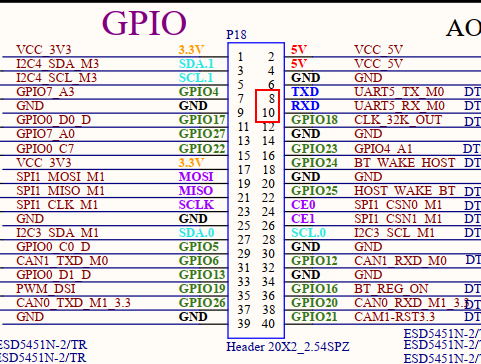
Once the shorting is complete, open the test program.
root@OK1126B-C-buildroot:/# fltest_uarttest -d /dev/ttyS5
Welcome to uart test
Send test data:
forlinx_uart_test.1234567890...
Read Test Data finished,Read:
forlinx_uart_test.1234567890...
If the following content is printed on the serial port after execution, it indicates that the serial communication is working normally.
4.6 SPI Test
One SPI interface is routed out from the carrier board. By default, the software configures it as spidev for loopback testing. During testing, please refer to the schematic diagram and short-circuit MOSI (PIN19) to MISO (PIN21), then carry out the test using the commands below.
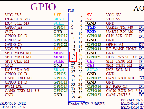
Without shorting SPI1_MOSI to SPI1_MISO, execute the test command:
root@OK1126B-C-buildroot:/# fltest_spidev_test -D /dev/spidev1.0
spi mode: 0
bits per word: 8
max speed: 500000 Hz (500 KHz)

FF FF FF FF FF FF
FF FF FF FF FF FF
FF FF FF FF FF FF
FF FF FF FF FF FF
FF FF FF FF FF FF
FF FF FF FF FF FF
FF FF
Short-circuit SPI1_MOSI and SPI1_MISO, then execute the test command:
root@OK1126B-C-buildroot:/# fltest_spidev_test -D /dev/spidev1.0
spi mode: 0
bits per word: 8
max speed: 500000 Hz (500 KHz)

FF FF FF FF FF FF
40 00 00 00 00 95
FF FF FF FF FF FF
FF FF FF FF FF FF
FF FF FF FF FF FF
DE AD BE EF BA AD
F0 0D
4.7 Watchdog Test
The watchdog is a critical feature in embedded systems for system recovery. The device node for the watchdog on OK1126B-C/OK1126BJ-C is /dev/watchdog0. This test provides two testing programs. You can choose one based on the actual situation.
Start fltest_watchdog, set the reset time to 10 seconds, and feed the dog at regular intervals.
root@OK1126B-C-buildroot:/# fltest_watchdog
Watchdog Ticking Away!
This command will activate the watchdog and perform the dog-feeding operation, preventing the system from restarting.
Note: If the test program is terminated with Ctrl+C, the system will reset after 10 seconds. To prevent the reset, input the following command within 10 seconds after pressing Ctrl+C:
root@OK1126B-C-buildroot:/# fltest_watchdog -d
Watchdog card disabled.   //Disable the watchdog
Start fltest_watchdog, set the reset time to 10 seconds, and do not feed the dog.
root@OK1126B-C-buildroot:/# fltest_watchdog -e
[  181.507014] watchdog: watchdog0: watchdog did not stop!
Watchdog card enabled.
This command will activate the watchdog but will not feed the dog. The system will restart after 10 seconds.
4.8 RTC Function Test
Mainly use the date and hwclock tools to set the software and hardware time. Test whether the software clock is synchronized with the RTC clock when the development board is powered off and then powered on. (Note: Ensure that a button battery is installed on the board and the battery voltage is normal.)
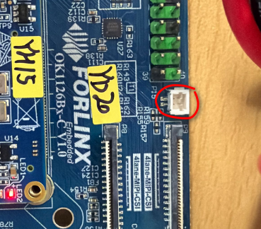
root@OK1126B-C-buildroot:/# date -s "2022-2-9 10:50:00"  // Set the time
Wed Feb  9 10:50:00 UTC 2022
root@OK1126B-C-buildroot:/# date                         // Read the time
Wed Feb  9 10:51:00 UTC 2022
root@OK1126B-C-buildroot:/# hwclock -w -u                // Write the system time (with timezone calculation) to the RTC
root@OK1126B-C-buildroot:/# hwclock -r                   // View the hardware time
Wed Feb  9 02:50:14 2022  0.000000 seconds
// Reboot the development board, then read the system time after booting to check if it matches the set time. Note: Do not connect to the internet, otherwise automatic time synchronization may occur.
root@OK1126B-C-buildroot:/# date
Wed Feb  9 10:52:00 UTC 2022
4.9 USB 2.0/USB3.0
OK1126B-C/OK1126BJ-C supports one USB2.0 and one USB3.0 interface. You can connect USB devices to any of the onboard USB HOST interfaces, and hot plugging is supported. In addition, it features a Type-C port, which can be used for flashing the device in Device mode. When the power is off, set the S2 DIP switch to OFF. When connecting OK1126B-C/OK1126BJ-C to a PC using a Type-C cable, configure it to Device mode. When the power is off and the S2 DIP switch is set to ON, configure it to Host mode, allowing devices such as U-disks to be inserted into the USB3.0 interface.
USB3.0 and OTG are multiplexed and can be switched for use through a DIP switch. When using the USB3.0 interface, please confirm that the DIP switch is in the ON position. Here, mounting a USB flash drive for demonstration.
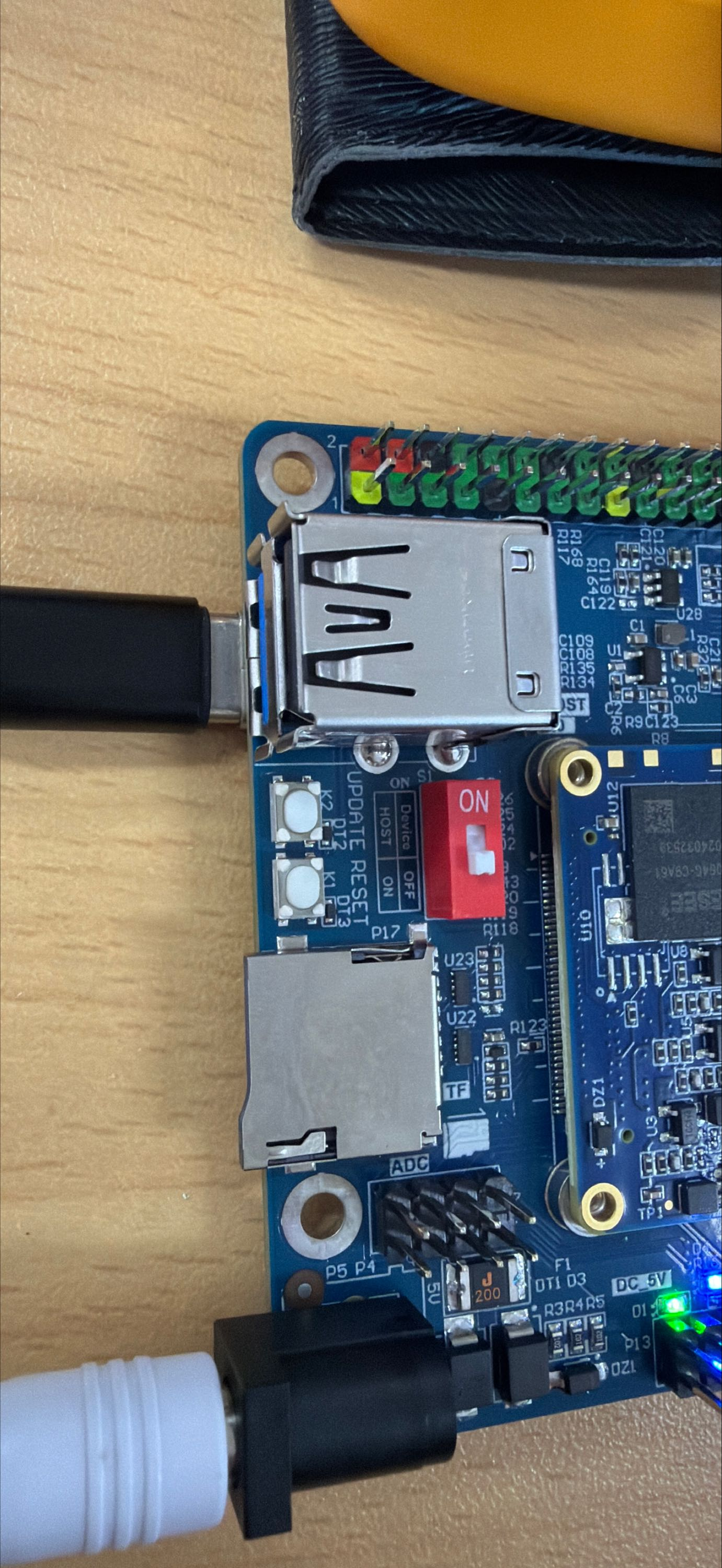
The USB 3.0 and OTG are multiplexed, and switching is done via a DIP switch. When using the USB 3.0 interface, ensure the DIP switch is in the ON position:
The terminal will print information about the USB drive. Since there are various USB drives, the displayed information may vary.
Step 1: After booting the development board, connect a USB flash drive to one of the USB host interfaces on the development board;
Serial port information (since the kernel’s default print level is 1, these prints will not actually be displayed and need to be viewed using dmesg):
root@OK1126B-C-buildroot:/#  [12775.292820] usb 1-1: new high-speed USB device number 3 using ehci-platform
[12775.453656] usb 1-1: New USB device found, idVendor=0781, idProduct=5567, bcdDevice= 1.00
[12775.453669] usb 1-1: New USB device strings: Mfr=1, Product=2, SerialNumber=3
[12775.453676] usb 1-1: Product: Cruzer Blade
[12775.453682] usb 1-1: Manufacturer: SanDisk
[12775.453687] usb 1-1: SerialNumber: 03000310123123023701
[12775.454149] usb-storage 1-1:1.0: USB Mass Storage device detected
[12775.454487] scsi host0: usb-storage 1-1:1.0
[12776.457856] scsi 0:0:0:0: Direct-Access     SanDisk  Cruzer Blade     1.00 PQ: 0 ANSI: 6
[12776.476175] sd 0:0:0:0: [sda] 60125184 512-byte logical blocks: (30.8 GB/28.7 GiB)
[12776.477712] sd 0:0:0:0: [sda] Write Protect is off
[12776.478837] sd 0:0:0:0: [sda] Write cache: disabled, read cache: enabled, doesn't support DPO or FUA
[12776.502348]  sda: sda1
[12776.502772] sd 0:0:0:0: [sda] Attached SCSI removable disk
[12777.398167] FAT-fs (sda1): utf8 is not a recommended IO charset for FAT filesystems, filesystem will be case sensitive!
[12777.428876] FAT-fs (sda1): Volume was not properly unmounted. Some data may be corrupt. Please run fsck.
Step 2: Check the mount directory:
root@OK1126B-C-buildroot:/# ls /run/media/
Step 3: View the contents of the USB flash drive:
root@OK1126B-C-buildroot:/# ls -l /run/media/sda1/
drwxrwx--- 3 root disk      8192 Mar  4  2021  Music
Before performing read/write tests, ensure the CPU frequency is noted.
Write test:
root@OK1126B-C-buildroot:/# dd if=/dev/zero of=/run/media/sda1/test.bin bs=1M count=100 conv=fsync oflag=direct
100+0 records in
100+0 records out
104857600 bytes (105 MB, 100 MiB) copied, 9.9486 s, 10.5 MB/s
//Write speeds are dependent on the specific storage device.
Read test:
root@OK1126B-C-buildroot:/# dd if=/run/media/sda1/test.bin of=/dev/null bs=1M iflag=direct
100+0 records in
100+0 records out
104857600 bytes (105 MB, 100 MiB) copied, 3.38621 s, 31.0 MB/s
4.10 Backlight Adjustment
The brightness setting range for the backlight is (0–255), where 255 indicates the highest brightness and 0 indicates the backlight brightness is turned off (note: MIPI-DSI screen backlight is controlled by GPIO, and the brightness only has two states: 0 and 1). Enter the following command in the terminal after system startup for backlight testing.
Check the current screen backlight value:
root@OK1126B-C-buildroot:/# cat /sys/class/backlight/backlight-dsi/brightness  // View MIPI-DSI screen backlight value
1
root@OK1126B-C-buildroot:/# cat /sys/class/backlight/backlight-lcd/brightness  // View RGB screen backlight value
200
Turn off the backlight:
root@OK1126B-C-buildroot:/# echo 0 > /sys/class/backlight/backlight-dsi/brightness  // Turn off MIPI-DSI screen backlight
root@OK1126B-C-buildroot:/# echo 0 > /sys/class/backlight/backlight-lcd/brightness  // Turn off RGB screen backlight
Turn on the LCD backlight:
root@OK1126B-C-buildroot:/# echo 1 > /sys/class/backlight/backlight-dsi/brightness  // Turn on MIPI-DSI screen backlight
root@OK1126B-C-buildroot:/# echo 255 > /sys/class/backlight/backlight-lcd/brightness  // Turn on RGB screen backlight
4.11 TF Test
Insert the TF card into the TF card slot on the development board’s carrier board. Under normal circumstances, the development board terminal will display the following print information (which can only be seen if the log level is set to 7 in the U-Boot menu):
root@OK1126B-C-buildroot:/#  [13658.430039] mmc_host mmc1: Bus speed (slot 0) = 198000000Hz (slot req 200000000Hz, actual 198000000HZ div = 0)

[13658.440111] dwmmc_rockchip 21d60000.mmc: Successfully tuned phase to 135
[13658.440129] mmc1: new ultra high speed SDR104 SDHC card at address aaaa
[13658.441331] mmcblk1: mmc1:aaaa SA16G 14.8 GiB
[13658.444704]  mmcblk1: p1
[13658.558032] FAT-fs (mmcblk1p1): utf8 is not a recommended IO charset for FAT filesystems, filesystem will be case sensitive!
[13658.562004] FAT-fs (mmcblk1p1): Volume was not properly unmounted. Some data may be corrupt. Please run fsck.
By default, the TF card is mounted to the file system directory /run/media/mmcblk1p1/.
root@OK1126B-C-buildroot:/# mount | grep mmcblk1             //View mounted directories
/dev/mmcblk1p1 on /run/media/mmcblk1p1 type vfat (rw,relatime,gid=6,fmask=0007,dmask=0007,allow_utime=0020,codepage=936,iocharset=utf8,shortname=mixed,errors=remount-ro)
Write test:
root@OK1126B-C-buildroot:/# dd if=/dev/zero of=/run/media/mmcblk1p1/test.bin bs=1M count=100 oflag=direct
100+0 records in
100+0 records out
104857600 bytes (105 MB, 100 MiB) copied, 2.67567 s, 39.2 MB/s
Read test:
root@OK1126B-C-buildroot:/# dd if=/run/media/mmcblk1p1/test.bin of=/dev/null bs=1M iflag=direct
100+0 records in
100+0 records out
104857600 bytes (105 MB, 100 MiB) copied, 1.17493 s, 89.2 MB/s
4.12 EMMC Test
OK1126B-C/ The eMMC on the OK1126BJ-C platform operates by default in HS400 mode at a clock speed of 200 MHz. Below is a brief test of the eMMC’s read and write speeds, using the ext4 file system as an example.
root@OK1126B-C-buildroot:/# dd if=/dev/zero of=/test bs=1M count=500 conv=fsync oflag=direct	//Write test
500+0 records in
500+0 records out
524288000 bytes (524 MB, 500 MiB) copied, 3.22593 s, 163 MB/s
root@OK1126B-C-buildroot:/# dd if=/test of=/dev/null bs=1M iflag=direct //读取测试
500+0 records in
500+0 records out
524288000 bytes (524 MB, 500 MiB) copied, 3.02095 s, 174 MB/s
4.13 Ethernet Configuration
The OK1126B-C/OK1126BJ-C is equipped with one Gigabit Ethernet port and one 100 Mbps Ethernet port; however, as the main controller has only one Ethernet controller, only one port can be used at a time. The Gigabit Ethernet port is selected by default; you can switch between the 100 Mbps and Gigabit Ethernet ports via the U-Boot menu. For specific instructions, please refer to section 2.5.1.
4.13.1 Methods for Setting a Static IP Address
Note: This method sets a static network IP. Once configured, the network interface card (NIC) should obtain the corresponding network IP, which indicates normal operation. If the network is unreachable (ping fails), ensure that multiple NIC in the same subnet are configured correctly. Adjust the routing based on the scenario or use different subnets by default.
Development board IP: 192.168.0.232
Router IP: 192.168.0.1
Subnet mask: 255.255.255.0
Power on the development board and execute the following commands.
root@OK1126B-C-buildroot:/# vi /etc/systemd/network/10-eth0.network   // Open the configuration file

[Match]
Name=eth0                                            // Specify the network card for which to set a static IP
KernelCommandLine=!root=/dev/nfs

[Network]
Address=192.168.0.232/24                            // Specify the static IP address and subnet mask
Gateway=192.168.0.1                                 // Specify the gateway
DNS=114.114.114.114                                 // Specify the DNS server

// Save and exit, then reboot the board.
4.13.2 Automatic IP Acquisition
root@OK1126B-C-buildroot:/# vi /etc/systemd/network/10-eth0.network   	//Open the configuration file
[Match]
Name=eth0
KernelCommandLine=!root=/dev/nfs
[Network]
DHCP=yes

//Save, exit, then restart the board
4.14 Playback/Recording Test
The development board features one white XH2.54-2P socket (P11), capable of driving an 4Ω speaker with a maximum output power of 3.3W. Before conducting an audio playback test, please plug the speaker into the corresponding socket on the carrier board and use the following command to perform the test:
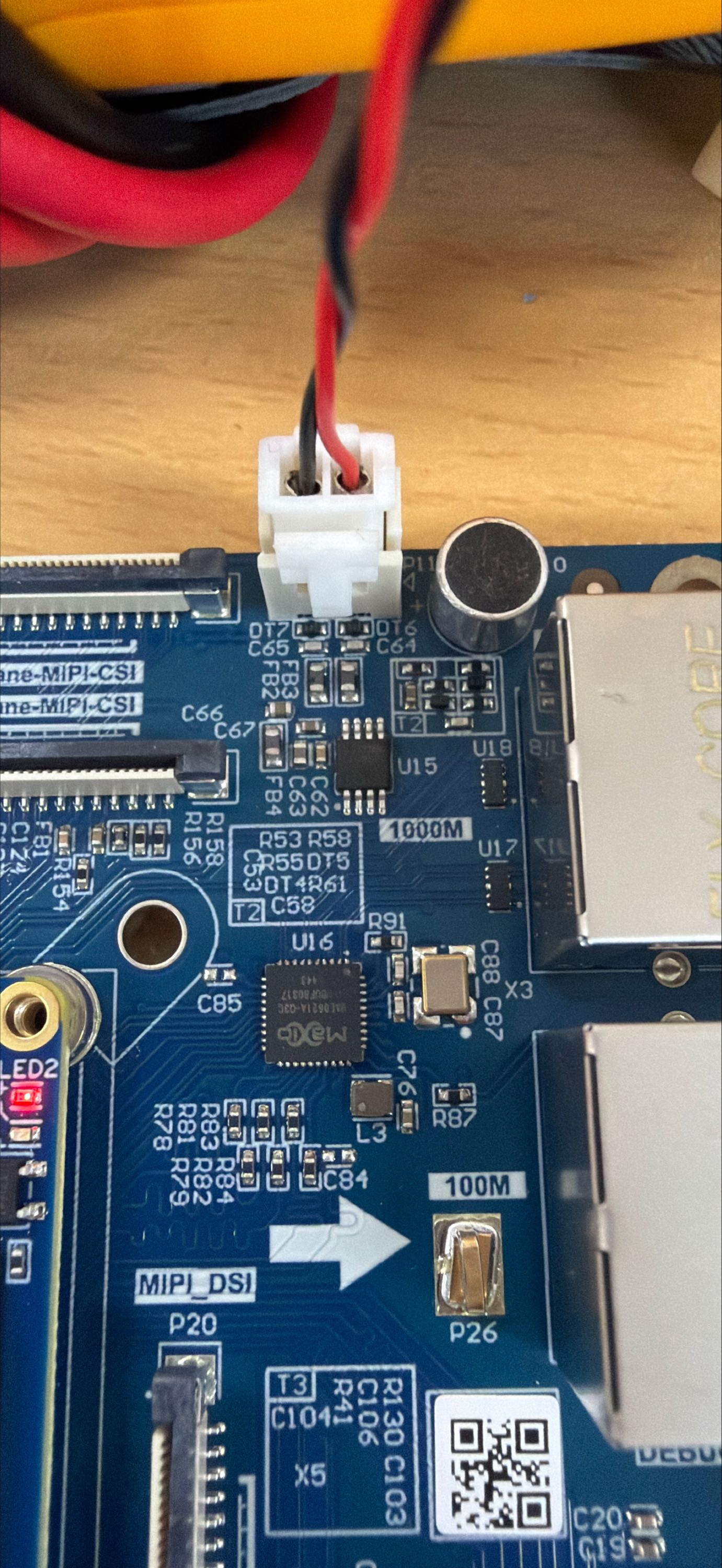
root@OK1126B-C-buildroot:/# gst-play-1.0 /userdata/piano2-CoolEdit.mp3
// Speaker audio playback test
Press 'k' to see a list of keyboard shortcuts.
Now playing /userdata/piano2-CoolEdit.mp3
Redistribute latency...
Redistribute latency...
0:00:06.3 / 0:00:06.3
Reached end of play list.

root@OK1126B-C-buildroot:/# arecord -c 2 -r 44100 -f cd mic.wav
// Recording test, press Ctrl + C to stop recording.
Recording WAVE 'mic.wav' : Signed 16 bit Little Endian, Rate 44100 Hz, Stereo
Aborted by signal Interrupt...

root@OK1126B-C-buildroot:/# ls  // The generated recording file can be seen in the current directory
bin		  data	etc   klogd.pid  lib64	  lost+found  mic.wav  oem  proc	   root  sbin  syslogd.pid  target  tmp       usr  vendor
busybox.fragment  dev	info  lib	 linuxrc  media       mnt      opt  rockchip-test  run	 sys   system	    test    userdata  var

root@OK1126B-C-buildroot:/# aplay mic.wav  // Play the recorded audio
4.15 NPU Test
The OK1126B-C/OK1126BJ-C platform supports the NPU; you can use the following commands to test the NPU.
root@OK1126B-C-buildroot:/# rknn_common_test  /usr/share/model/RV1126B/mobilenet_v1.rknn /usr/share/model/cat_224x224.jpg
rknn_api/rknnrt version: 2.3.2 (429f97ae6b@2025-04-09T09:09:27), driver version: 0.9.8
model input num: 1, output num: 1
input tensors:
  index=0, name=input, n_dims=4, dims=[1, 224, 224, 3], n_elems=150528, size=150528, fmt=NHWC, type=INT8, qnt_type=AFFINE, zp=0, scale=0.007812
output tensors:
  index=0, name=MobilenetV1/Predictions/Reshape_1, n_dims=2, dims=[1, 1001, 0, 0], n_elems=1001, size=2002, fmt=UNDEFINED, type=FP16, qnt_type=AFFINE, zp=0, scale=1.000000
custom string:
Begin perf ...
   0: Elapse Time = 2.79ms, FPS = 358.55
---- Top5 ----
0.407959 - 283
0.172729 - 282
0.154785 - 286
0.059204 - 278
0.042664 - 279
Rockchip provides a comprehensive set of test cases; please refer to the NPU section in the application notes for compilation and testing.
4.16 LED Test
The OK1126B-C/OK1126BJ-C SoM features a controllable blue LED; this LED flashes when the board is powered up. You can disable this feature by modifying the device tree file arch/arm64/boot/dts/rockchip/FET1126B-C.dtsi to add the attribute default-state = “off” to the LEDs node, and change linux,default-trigger to “none”.
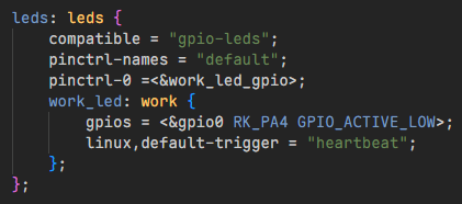
Testing Procedure:
Change the blue LED to a standard GPIO-controlled LED.
root@OK1126B-C-buildroot:/# cd /sys/class/leds/work/
root@OK1126B-buildroot:/sys/class/leds/work# echo gpio > trigger
Test by switching on the LED lights
root@OK1126B-buildroot:/sys/class/leds/work# echo 1 > brightness
Test by switching on the LED lights
root@OK1126B-buildroot:/sys/class/leds/work# echo 0 > brightness
Change the blue LED to a heartbeat LED.
root@OK1126B-buildroot:/sys/class/leds/work# echo heartbeat > trigger
4.17 ADC Test
P7 is the ADC pin as shown in the figure below, where SARADC0 _ IN0-IN6 correspond to 0-6 of the ADC channel respectively.
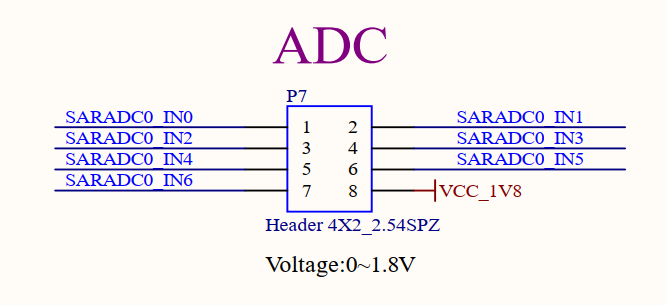
Enter the following command to view the value of the ADC channel (range 0–8192):
root@OK1126B-C-buildroot:/# cat /sys/bus/iio/devices/iio\:device0/in_voltage0_raw
8191
root@OK1126B-C-buildroot:/# cat /sys/bus/iio/devices/iio\:device0/in_voltage1_raw
334
root@OK1126B-C-buildroot:/# cat /sys/bus/iio/devices/iio\:device0/in_voltage2_raw
673
root@OK1126B-C-buildroot:/# cat /sys/bus/iio/devices/iio\:device0/in_voltage3_raw
710
root@OK1126B-C-buildroot:/# cat /sys/bus/iio/devices/iio\:device0/in_voltage4_raw
519
root@OK1126B-C-buildroot:/# cat /sys/bus/iio/devices/iio\:device0/in_voltage5_raw
442
root@OK1126B-C-buildroot:/# cat /sys/bus/iio/devices/iio\:device0/in_voltage6_raw
408
4.18 SQLite3 Test
SQLite3 is a lightweight database system, an ACID-compliant relational database management system with low resource consumption. The OK1126B-C/OK1126BJ-C development board is ported with the SQLite 3.44.2 version.
root@OK1126B-C-buildroot:/# sqlite3
SQLite version 3.44.2 2023-11-24 11:41:44
Enter ".help" for usage hints.
Connected to a transient in-memory database.
Use ".open FILENAME" to reopen on a persistent database.
sqlite> create table tbl1 (one varchar(10), two smallint);  // Create table tbl1
sqlite> insert into tbl1 values('hello!',10);                // Insert data into tbl1
sqlite> insert into tbl1 values('goodbye', 20);              // Insert data into tbl1: goodbye|20
sqlite> select * from tbl1;                                // Query the contents of table tbl1
hello!|10
goodbye|20
sqlite> delete from tbl1 where one = 'hello!';              // Delete data
sqlite> select * from tbl1;                                // Query the contents of table tbl1
goodbye|20
sqlite> .quit                                              // Exit the database (or use .exit)
root@OK1126B-C-buildroot:/#
4.19 4G Test
OK1126B-C/OK1126BJ-C supports the 4G module EM05 (connected via USB). Prepare the 4G module adapter board FIT-4G&5G V1.0-PC. Before starting the development board, insert the 4G module EM05 into the adapter board, insert the SIM card into the adapter board, connect the antenna from the adapter board to the EM05 and the antenna on the adapter board, and power the adapter board with a 12V power supply. Power on the development board.
Short-press the power button on the adapter board and wait for the green LED to illuminate.
The numbers in the diagram (from small to large) correspond to:
12V Power Input
Power Button
SIM Card Slot
USB Cable Connector
4G Module EM05
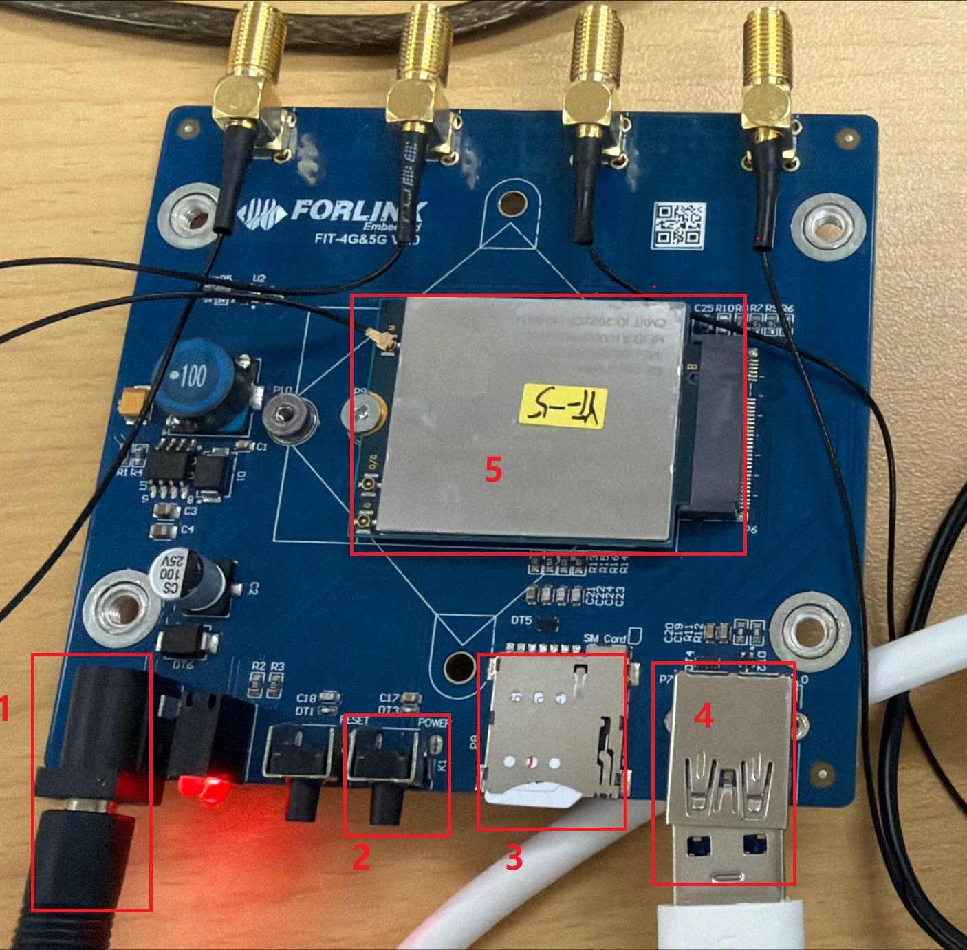
After the development board boots, execute the lsusb command in the debug serial console to verify module detection.
root@OK1126B-C-buildroot:/# lsusb
Bus 001 Device 001: ID 1d6b:0002
Bus 001 Device 002: ID 2c7c:0125		#This is the 4G module
Bus 002 Device 001: ID 1d6b:0001
Check the device node status under /dev.
root@OK1126B-C-buildroot:/# ls /dev/ttyUSB*
/dev/ttyUSB0  /dev/ttyUSB1  /dev/ttyUSB2  /dev/ttyUSB3
After successful device identification, you can perform dial-up Internet access testing;
root@OK1126B-C-buildroot:/# quectelCM &
[03-12_02:39:28:848] QConnectManager_Linux_V1.6.7
[03-12_02:39:28:849] Find /sys/bus/usb/devices/1-1 idVendor=0x2c7c idProduct=0x125, bus=0x001, dev=0x002
[03-12_02:39:28:849] Auto find qmichannel = /dev/cdc-wdm0
[03-12_02:39:28:849] Auto find usbnet_adapter = wwan0
[03-12_02:39:28:849] netcard driver = qmi_wwan, driver version = 6.1.141
[03-12_02:39:28:850] Modem works in QMI mode
[03-12_02:39:28:857] cdc_wdm_fd = 7
[03-12_02:39:29:858] QmiWwanInit message timeout
[03-12_02:39:30:944] Get clientWDS = 5
[03-12_02:39:30:976] Get clientDMS = 1
[03-12_02:39:31:008] Get clientNAS = 2
[03-12_02:39:31:040] Get clientUIM = 1
[03-12_02:39:31:072] Get clientWDA = 1
[03-12_02:39:31:104] requestBaseBandVersion EM05CNFDR08A03M1G_ND
[03-12_02:39:31:232] requestGetSIMStatus SIMStatus: SIM_READY
[03-12_02:39:31:296] requestGetProfile[pdp:1 index:1] cmnet///0/IPV4V6
[03-12_02:39:31:328] requestRegistrationState2 MCC: 460, MNC: 0, PS: Attached, DataCap: LTE
[03-12_02:39:31:360] requestQueryDataCall IPv4ConnectionStatus: DISCONNECTED
[03-12_02:39:31:360] ip addr flush dev wwan0
[03-12_02:39:31:366] ip link set dev wwan0 down
[03-12_02:39:31:424] requestSetupDataCall WdsConnectionIPv4Handle: 0x87696660
[03-12_02:39:31:552] ip link set dev wwan0 up
[03-12_02:39:31:564] busybox udhcpc -f -n -q -t 5 -i wwan0
udhcpc: started, v1.36.1
udhcpc: broadcasting discover
udhcpc: broadcasting discover
udhcpc: broadcasting discover
udhcpc: broadcasting discover
udhcpc: broadcasting discover
udhcpc: no lease, failing
[03-12_02:39:46:832] File:ql_raw_ip_mode_check Line:143 udhcpc fail to get ip address, try next:
[03-12_02:39:46:832] ip link set dev wwan0 down
[03-12_02:39:46:843] echo Y > /sys/class/net/wwan0/qmi/raw_ip
[03-12_02:39:46:843] ip link set dev wwan0 up
[03-12_02:39:46:851] busybox udhcpc -f -n -q -t 5 -i wwan0
udhcpc: started, v1.36.1
udhcpc: broadcasting discover
udhcpc: broadcasting select for 100.10.77.48, server 100.10.77.49
udhcpc: lease of 100.10.77.48 obtained from 100.10.77.49, lease time 7200
[03-12_02:39:47:049] deleting routers
[03-12_02:39:47:074] adding dns 111.11.11.3
[03-12_02:39:47:074] adding dns 111.11.1.3
Once connected to the internet, the domain name can be pinged.
root@OK1126B-C-buildroot:/# ping -I wwan0 www.baidu.com -c 3
PING www.a.shifen.com (110.242.69.21) from 10.113.84.102 wwan0: 56(84) bytes of data.
64 bytes from 110.242.69.21: icmp_seq=1 ttl=54 time=67.9 ms
64 bytes from 110.242.69.21: icmp_seq=2 ttl=54 time=39.3 ms
64 bytes from 110.242.69.21: icmp_seq=3 ttl=54 time=34.4 ms

--- www.a.shifen.com ping statistics ---
3 packets transmitted, 3 received, 0% packet loss, time 8805ms
rtt min/avg/max/mdev = 34.399/47.212/67.941/14.793 ms
5. OK1126B-C_Platform Multimedia Test
The application-layer software for the audio and video components of the OK1126B-C/OK1126BJ-C platform utilises GStreamer and supports hardware-based encoding and decoding. All examples in this section are based on Gstreamer commands. If you need a player with a GUI, you can also use Qt multimedia classes, which also support hardware-accelerated encoding. Please refer to the Qt test section for more details.
The OK1126B-C/OK1126BJ-C platform features a video processing unit (VPU) that supports hardware encoding and decoding of the following video formats:
Video Decoding: H.264, H.265, supports up to 4K@30fps
Video Encoding H.264, H.265, supports up to 12M@30fps
OK1126B-C/OK1126BJ-C Platform Hardware Codec Parameter Table:
Format |
Profile |
Resolution |
Frame rate |
|
|---|---|---|---|---|
Video Encoder |
HEVC |
Level 5.0 High Tier |
12M |
30 fps |
H.264 |
Level 5.0 |
12M |
30 fps |
|
Video Decoder |
H.264 |
yuv400/yuv420/yuv422@L5.1 |
3840x2160 |
30 fps |
H.265 |
yuv420@L5.0 |
3840x2160 |
30 fps |
5.1 Audio and Video Playback Experience
5.1.1 Playing Video and Audio via Gplay
Gplay is an audio and video player based on Gstreamer. It automatically selects the appropriate plugins for audio and video playback based on the hardware, and it is very easy to use.
root@OK1126B-C-buildroot:/# gst-play-1.0 /userdata/media/1080p_30fps_h265.mp4
//Play a video file with sound and test the audio output through the speakers
Press 'k' to see a list of keyboard shortcuts.
Now playing /userdata/media/1080p_30fps_h265.mp4
Redistribute latency...
Redistribute latency...
mpp[1903]: mpp_info: mpp version: unknown mpp version for missing VCS info
mpp[1903]: mpp_info: mpp version: unknown mpp version for missing VCS info
mpp[1903]: mpp_info: mpp version: unknown mpp version for missing VCS info
mpp[1903]: mpp: unable to create enc vp8 for soc rv1126b unsupported
mpp[1903]: mpp_info: mpp version: unknown mpp version for missing VCS info
mpp[1903]: mpp_info: mpp version: unknown mpp version for missing VCS info
Redistribute latency...
Redistribute latency...
mpp[1903]: H265D_PARSER: extradata is encoded as hvcC format
mpp[1903]: mpp_buf_slot: mismatch h_stride_by_pixel 1984 - 1920
mpp[1903]: mpp_buf_slot: mismatch h_stride_by_byte 1984 - 1920
mpp[1903]: mpp_buf_slot: mismatch size_total 3856896 - 3732480
mpp[1903]: mpp_buf_slot: mismatch h_stride_by_pixel 1984 - 1920
mpp[1903]: mpp_buf_slot: mismatch h_stride_by_byte 1984 - 1920
mpp[1903]: mpp_buf_slot: mismatch size_total 3856896 - 3732480
Redistribute latency...
5.1.2 Playing Video via Gst-launch
root@OK1126B-C-buildroot:/# gst-launch-1.0 filesrc location=/userdata/media/1080p_30fps_h265.mp4 ! qtdemux ! queue ! h265parse ! mppvideodec ! waylandsink
//Only play the video
mpp[1922]: mpp_info: mpp version: unknown mpp version for missing VCS info
mpp[1922]: mpp_info: mpp version: unknown mpp version for missing VCS info
mpp[1922]: mpp_info: mpp version: unknown mpp version for missing VCS info
mpp[1922]: mpp: unable to create enc vp8 for soc rv1126b unsupported
mpp[1922]: mpp_info: mpp version: unknown mpp version for missing VCS info
Setting pipeline to PAUSED ...
mpp[1922]: mpp_info: mpp version: unknown mpp version for missing VCS info
Pipeline is PREROLLING ...
Redistribute latency...
Redistribute latency...
mpp[1922]: H265D_PARSER: extradata is encoded as hvcC format
mpp[1922]: mpp_buf_slot: mismatch h_stride_by_pixel 1984 - 1920
mpp[1922]: mpp_buf_slot: mismatch h_stride_by_byte 1984 - 1920
mpp[1922]: mpp_buf_slot: mismatch size_total 3856896 - 3732480
mpp[1922]: mpp_buf_slot: mismatch h_stride_by_pixel 1984 - 1920
mpp[1922]: mpp_buf_slot: mismatch h_stride_by_byte 1984 - 1920
mpp[1922]: mpp_buf_slot: mismatch size_total 3856896 - 3732480
Pipeline is PREROLLED ...
Prerolled, waiting for async message to finish...
Setting pipeline to PLAYING ...
Redistribute latency...
New clock: GstSystemClock
[00:04:46.015] seeing the first app
Got EOS from element "pipeline0".
Execution ended after 0:00:30.633824472
Setting pipeline to NULL ...
Freeing pipeline ...
5.1.3 Playing Audio via Gst-launch
root@OK1126B-C-buildroot:/# gst-launch-1.0 filesrc location=/userdata/media/test.mp3 ! id3demux ! mpegaudioparse ! mpg123audiodec ! alsasink
//Play audio only; test the sound output via the speakers,
Setting pipeline to PAUSED ...
Pipeline is PREROLLING ...
Redistribute latency...
Pipeline is PREROLLED ...
Prerolled, waiting for async message to finish...
Setting pipeline to PLAYING ...
Redistribute latency...
New clock: GstAudioSinkClock
^Chandling interrupt. (0.8 %)
Interrupt: Stopping pipeline ...
Execution ended after 0:00:02.321717834
Setting pipeline to NULL ...
Freeing pipeline ...
5.1.4 Playing Both Video and Audio via Gst-launch
root@OK1126B-C-buildroot:/# gst-launch-1.0 filesrc location=/userdata/media/1080p_30fps_h265.mp4 ! qtdemux name=dec dec. ! queue ! h265parse ! mppvideodec ! waylandsink dec.! queue ! decodebin ! alsasink
//Play a video file with sound and test the audio output through the speakers
mpp[1960]: mpp_info: mpp version: unknown mpp version for missing VCS info
mpp[1960]: mpp_info: mpp version: unknown mpp version for missing VCS info
mpp[1960]: mpp_info: mpp version: unknown mpp version for missing VCS info
mpp[1960]: mpp: unable to create enc vp8 for soc rv1126b unsupported
mpp[1960]: mpp_info: mpp version: unknown mpp version for missing VCS info
Setting pipeline to PAUSED ...
mpp[1960]: mpp_info: mpp version: unknown mpp version for missing VCS info
Pipeline is PREROLLING ...
Redistribute latency...
Redistribute latency...
mpp[1960]: H265D_PARSER: extradata is encoded as hvcC format
mpp[1960]: mpp_buf_slot: mismatch h_stride_by_pixel 1984 - 1920
mpp[1960]: mpp_buf_slot: mismatch h_stride_by_byte 1984 - 1920
mpp[1960]: mpp_buf_slot: mismatch size_total 3856896 - 3732480
mpp[1960]: mpp_buf_slot: mismatch h_stride_by_pixel 1984 - 1920
mpp[1960]: mpp_buf_slot: mismatch h_stride_by_byte 1984 - 1920
mpp[1960]: mpp_buf_slot: mismatch size_total 3856896 - 3732480
Redistribute latency...
Redistribute latency...
Pipeline is PREROLLED ...
Prerolled, waiting for async message to finish...
Setting pipeline to PLAYING ...
New clock: GstAudioSinkClock
Redistribute latency...
^Chandling interrupt. (24.9 %)
Interrupt: Stopping pipeline ...
Execution ended after 0:00:07.698089754
Setting pipeline to NULL ...
mpp[1960]: H265D_PARSER: extradata is encoded as hvcC format
Freeing pipeline ...
5.2 Video Hardware Encoding
The OK1126B-C/OK1126BJ-C supports H.264/H.265 video encoding at up to 12M@30fps and high-quality JPEG encoding and decoding.
5.2.1 Video Hardware Encoding H.264
root@OK1126B-C-buildroot:/# gst-launch-1.0 mp4mux name=mux ! filesink location=test.mp4  videotestsrc num-buffers=600 ! video/x-raw,framerate=60/1,width=1920,height=1080,format=NV12 ! mpph264enc ! h264parse !  mux.video_0 -e
mpp[1974]: mpp_info: mpp version: unknown mpp version for missing VCS info
mpp[1974]: mpp_info: mpp version: unknown mpp version for missing VCS info
mpp[1974]: mpp_info: mpp version: unknown mpp version for missing VCS info
mpp[1974]: mpp: unable to create enc vp8 for soc rv1126b unsupported
mpp[1974]: mpp_info: mpp version: unknown mpp version for missing VCS info
Setting pipeline to PAUSED ...
mpp[1974]: mpp_info: mpp version: unknown mpp version for missing VCS info
mpp[1974]: mpp: Only rk3588's h264/265/jpeg and rk3576's h264/265 encoder can use frame parallel
Pipeline is PREROLLING ...
mpp[1974]: mpp_enc: MPP_ENC_SET_RC_CFG bps 15552000 [14580000 : 16524000] fps [60:60] gop 60
mpp[1974]: h264e_api_v2: MPP_ENC_SET_PREP_CFG w:h [1920:1080] stride [1920:1088]
mpp[1974]: mpp_enc: mode cbr bps [14580000:15552000:16524000] fps fix [60/1] -> fix [60/1] gop i [60] v [0]
Redistribute latency...
Pipeline is PREROLLED ...
Prerolled, waiting for async message to finish...
Setting pipeline to PLAYING ...
Redistribute latency...
New clock: GstSystemClock
Got EOS from element "pipeline0".
EOS received - stopping pipeline...
Execution ended after 0:00:18.377197925
Setting pipeline to NULL ...
Freeing pipeline ...
5.2.2 Video Hardware Encoding H.265
root@OK1126B-C-buildroot:/# gst-launch-1.0 mp4mux name=mux ! filesink location=test.mp4 videotestsrc num-buffers=600 ! video/x-raw,framerate=60/1,width=1920,height=1080,format=NV12 ! mpph265enc ! h265parse !  mux.video_0 -e
mpp[2007]: mpp_info: mpp version: unknown mpp version for missing VCS info
mpp[2007]: mpp_info: mpp version: unknown mpp version for missing VCS info
mpp[2007]: mpp_info: mpp version: unknown mpp version for missing VCS info
mpp[2007]: mpp: unable to create enc vp8 for soc rv1126b unsupported
mpp[2007]: mpp_info: mpp version: unknown mpp version for missing VCS info
Setting pipeline to PAUSED ...
mpp[2007]: mpp_info: mpp version: unknown mpp version for missing VCS info
mpp[2007]: mpp: Only rk3588's h264/265/jpeg and rk3576's h264/265 encoder can use frame parallel
Pipeline is PREROLLING ...
mpp[2007]: mpp_enc: MPP_ENC_SET_RC_CFG bps 15552000 [14580000 : 16524000] fps [60:60] gop 60
mpp[2007]: h265e_api: h265e_proc_prep_cfg MPP_ENC_SET_PREP_CFG w:h [1920:1080] stride [1920:1088]
mpp[2007]: mpp_enc: mode cbr bps [14580000:15552000:16524000] fps fix [60/1] -> fix [60/1] gop i [60] v [0]
Redistribute latency...
Pipeline is PREROLLED ...
Prerolled, waiting for async message to finish...
Setting pipeline to PLAYING ...
Redistribute latency...
New clock: GstSystemClock
Got EOS from element "pipeline0".
EOS received - stopping pipeline...
Execution ended after 0:00:18.489412842
Setting pipeline to NULL ...
Freeing pipeline ...
5.3 Video Hardware Decoding
The OK1126B-C/OK1126BJ-C supports hardware decoding for H.264 and H.265 video formats.
The H.264 decoder supports up to 4K@30fps.
The H.265 decoder supports up to 4K@30fps.
The OK1126B-C/OK1126BJ-C utilizes the mppvideodec component for hardware video decoding. Its output pixel formats are: NV12, I420, and YV12.
5.3.1 H.264 Video Decoding and Playback
root@OK1126B-C-buildroot:/# gst-launch-1.0 filesrc location=/userdata/media/1080p_60fps_h264.mp4 ! qtdemux ! h264parse ! mppvideodec ! waylandsink
mpp[2020]: mpp_info: mpp version: unknown mpp version for missing VCS info
mpp[2020]: mpp_info: mpp version: unknown mpp version for missing VCS info
mpp[2020]: mpp_info: mpp version: unknown mpp version for missing VCS info
mpp[2020]: mpp: unable to create enc vp8 for soc rv1126b unsupported
mpp[2020]: mpp_info: mpp version: unknown mpp version for missing VCS info
Setting pipeline to PAUSED ...
mpp[2020]: mpp_info: mpp version: unknown mpp version for missing VCS info
Pipeline is PREROLLING ...
Redistribute latency...
Redistribute latency...
mpp[2020]: h264d_api: is_avcC=1
mpp[2020]: mpp_buf_slot: mismatch h_stride_by_pixel 1984 - 1920
mpp[2020]: mpp_buf_slot: mismatch h_stride_by_byte 1984 - 1920
mpp[2020]: mpp_buf_slot: mismatch size_total 3237888 - 4177920
mpp[2020]: mpp_buf_slot: mismatch h_stride_by_pixel 1984 - 1920
mpp[2020]: mpp_buf_slot: mismatch h_stride_by_byte 1984 - 1920
mpp[2020]: mpp_buf_slot: mismatch size_total 3237888 - 4177920
Pipeline is PREROLLED ...
Prerolled, waiting for async message to finish...
Setting pipeline to PLAYING ...
Redistribute latency...
New clock: GstSystemClock
^Chandling interrupt. (12.3 %)
Interrupt: Stopping pipeline ...
Execution ended after 0:00:07.631453212
Setting pipeline to NULL ...
Freeing pipeline ...
5.3.2 H.264 Video Decoding and Playback with Audio
root@OK1126B-C-buildroot:/# gst-launch-1.0 filesrc location=/userdata/media/1080p_60fps_h264.mp4 ! qtdemux name=demux demux.video_0 ! queue ! h264parse ! mppvideodec  ! waylandsink demux.audio_0 ! queue ! aacparse ! faad ! alsasink
mpp[2031]: mpp_info: mpp version: unknown mpp version for missing VCS info
mpp[2031]: mpp_info: mpp version: unknown mpp version for missing VCS info
mpp[2031]: mpp_info: mpp version: unknown mpp version for missing VCS info
mpp[2031]: mpp: unable to create enc vp8 for soc rv1126b unsupported
mpp[2031]: mpp_info: mpp version: unknown mpp version for missing VCS info
Setting pipeline to PAUSED ...
mpp[2031]: mpp_info: mpp version: unknown mpp version for missing VCS info
Pipeline is PREROLLING ...
Redistribute latency...
Redistribute latency...
mpp[2031]: h264d_api: is_avcC=1
Redistribute latency...
Redistribute latency...
mpp[2031]: mpp_buf_slot: mismatch h_stride_by_pixel 1984 - 1920
mpp[2031]: mpp_buf_slot: mismatch h_stride_by_byte 1984 - 1920
mpp[2031]: mpp_buf_slot: mismatch size_total 3237888 - 4177920
mpp[2031]: mpp_buf_slot: mismatch h_stride_by_pixel 1984 - 1920
mpp[2031]: mpp_buf_slot: mismatch h_stride_by_byte 1984 - 1920
mpp[2031]: mpp_buf_slot: mismatch size_total 3237888 - 4177920
Pipeline is PREROLLED ...
Prerolled, waiting for async message to finish...
Setting pipeline to PLAYING ...
New clock: GstAudioSinkClock
Redistribute latency...
^Chandling interrupt. (6.6 %)
Interrupt: Stopping pipeline ...
Execution ended after 0:00:04.045597501
Setting pipeline to NULL ...
Freeing pipeline ...
5.3.3 H.265 Video Decoding and Playback
root@OK1126B-C-buildroot:/# gst-launch-1.0 filesrc location=/userdata/media/1080p_30fps_h265.mp4 ! qtdemux ! h265parse ! mppvideodec ! waylandsink
mpp[2045]: mpp_info: mpp version: unknown mpp version for missing VCS info
mpp[2045]: mpp_info: mpp version: unknown mpp version for missing VCS info
mpp[2045]: mpp_info: mpp version: unknown mpp version for missing VCS info
mpp[2045]: mpp: unable to create enc vp8 for soc rv1126b unsupported
mpp[2045]: mpp_info: mpp version: unknown mpp version for missing VCS info
Setting pipeline to PAUSED ...
mpp[2045]: mpp_info: mpp version: unknown mpp version for missing VCS info
Pipeline is PREROLLING ...
Redistribute latency...
Redistribute latency...
mpp[2045]: H265D_PARSER: extradata is encoded as hvcC format
mpp[2045]: mpp_buf_slot: mismatch h_stride_by_pixel 1984 - 1920
mpp[2045]: mpp_buf_slot: mismatch h_stride_by_byte 1984 - 1920
mpp[2045]: mpp_buf_slot: mismatch size_total 3856896 - 3732480
mpp[2045]: mpp_buf_slot: mismatch h_stride_by_pixel 1984 - 1920
mpp[2045]: mpp_buf_slot: mismatch h_stride_by_byte 1984 - 1920
mpp[2045]: mpp_buf_slot: mismatch size_total 3856896 - 3732480
Pipeline is PREROLLED ...
Prerolled, waiting for async message to finish...
Setting pipeline to PLAYING ...
New clock: GstSystemClock
Redistribute latency...
^Chandling interrupt. (11.5 %)
Interrupt: Stopping pipeline ...
Execution ended after 0:00:03.538232585
Setting pipeline to NULL ...
Freeing pipeline ...
5.3.4 H.265 Video Decoding and Playback with Audio
root@OK1126B-C-buildroot:/# gst-launch-1.0 filesrc location=/userdata/media/1080p_30fps_h265.mp4 ! qtdemux name=demux demux.video_0 ! queue ! h265parse ! mppvideodec  ! waylandsink demux.audio_0 ! queue ! aacparse ! faad ! alsasink
mpp[2056]: mpp_info: mpp version: unknown mpp version for missing VCS info
mpp[2056]: mpp_info: mpp version: unknown mpp version for missing VCS info
mpp[2056]: mpp_info: mpp version: unknown mpp version for missing VCS info
mpp[2056]: mpp: unable to create enc vp8 for soc rv1126b unsupported
mpp[2056]: mpp_info: mpp version: unknown mpp version for missing VCS info
Setting pipeline to PAUSED ...
mpp[2056]: mpp_info: mpp version: unknown mpp version for missing VCS info
Pipeline is PREROLLING ...
Redistribute latency...
Redistribute latency...
Redistribute latency...
Redistribute latency...
mpp[2056]: H265D_PARSER: extradata is encoded as hvcC format
mpp[2056]: mpp_buf_slot: mismatch h_stride_by_pixel 1984 - 1920
mpp[2056]: mpp_buf_slot: mismatch h_stride_by_byte 1984 - 1920
mpp[2056]: mpp_buf_slot: mismatch size_total 3856896 - 3732480
mpp[2056]: mpp_buf_slot: mismatch h_stride_by_pixel 1984 - 1920
mpp[2056]: mpp_buf_slot: mismatch h_stride_by_byte 1984 - 1920
mpp[2056]: mpp_buf_slot: mismatch size_total 3856896 - 3732480
Pipeline is PREROLLED ...
Prerolled, waiting for async message to finish...
Setting pipeline to PLAYING ...
Redistribute latency...
New clock: GstAudioSinkClock
^Chandling interrupt. (10.1 %)
Interrupt: Stopping pipeline ...
Execution ended after 0:00:03.158455085
Setting pipeline to NULL ...
mpp[2056]: H265D_PARSER: extradata is encoded as hvcC format
mpp[2056]: H265D_PARSER: extradata is encoded as hvcC format
mpp[2056]: H265D_PARSER: extradata is encoded as hvcC format
Freeing pipeline ...
5.4 Camera Test
The OK1126B-C/OK1126BJ-C supports the OS04A10 MIPI camera.
5.4.1 OS04A10 Test
5.4.1.1 Camera Recognition and Format Support Query
root@OK1126B-C-buildroot:/# v4l2-ctl --list-devices
//View device nodes
rkaiisp (platform: rkaiisp):
    /dev/video0

rkisp-statistics (platform: rkisp):
    /dev/video28
    /dev/video29
    /dev/video36
    /dev/video37

rkaiisp0 (platform:rkaiisp-vir0):
    /dev/media0

rkcif (platform:rkcif-mipi-lvds):
    /dev/video1
    /dev/video2
    /dev/video3
    /dev/video4
    /dev/video5
    /dev/video6
    /dev/video7
    /dev/video8
    /dev/video9
    /dev/video10
    /dev/video11
    /dev/media1

rkcif (platform:rkcif-mipi-lvds2):
    /dev/video12
    /dev/video13
    /dev/video14
    /dev/video15
    /dev/video16
    /dev/video17
    /dev/video18
    /dev/video19
    /dev/video20
    /dev/video21
    /dev/video22
    /dev/media2

rkisp_mainpath (platform:rkisp-vir0):
    /dev/video23
    /dev/video24
    /dev/video25
    /dev/video26
    /dev/video27
    /dev/video30
    /dev/media3

rkisp_mainpath (platform:rkisp-vir1):
    /dev/video31
    /dev/video32
    /dev/video33
    /dev/video34
    /dev/video35
    /dev/video38
    /dev/media4

rkvpss_scale0 (platform:rkvpss-vir0):
    /dev/video40
    /dev/video41
    /dev/video42
    /dev/video43
    /dev/video44
    /dev/video45
    /dev/media5

rkvpss_scale0 (platform:rkvpss-vir1):
    /dev/video46
    /dev/video47
    /dev/video48
    /dev/video49
    /dev/video50
    /dev/video51
    /dev/media6
root@OK1126B-C-buildroot:/# v4l2-ctl --list-formats-ext -d /dev/video23
//View the formats and resolutions supported by the camera
ioctl: VIDIOC_ENUM_FMT
    Type: Video Capture Multiplanar

    [0]: 'UYVY' (UYVY 4:2:2)
        Size: Stepwise 32x32 - 2688x1520 with step 8/8
    [1]: 'NV16' (Y/UV 4:2:2)
        Size: Stepwise 32x32 - 2688x1520 with step 8/8
    [2]: 'NV61' (Y/VU 4:2:2)
        Size: Stepwise 32x32 - 2688x1520 with step 8/8
    [3]: 'NV21' (Y/VU 4:2:0)
        Size: Stepwise 32x32 - 2688x1520 with step 8/8
    [4]: 'NV12' (Y/UV 4:2:0)
        Size: Stepwise 32x32 - 2688x1520 with step 8/8
    [5]: 'NM21' (Y/VU 4:2:0 (N-C))
        Size: Stepwise 32x32 - 2688x1520 with step 8/8
    [6]: 'NM12' (Y/UV 4:2:0 (N-C))
        Size: Stepwise 32x32 - 2688x1520 with step 8/8
    [7]: 'GREY' (8-bit Greyscale)
        Size: Stepwise 32x32 - 2688x1520 with step 8/8
    [8]: 'TIL2' (Rockchip yuv422 tile)
        Size: Stepwise 32x32 - 2688x1520 with step 8/8
    [9]: 'TIL0' (Rockchip yuv420 tile)
        Size: Stepwise 32x32 - 2688x1520 with step 8/8
5.4.1.2 Camera Preview
root@OK1126B-C-buildroot:/# gst-launch-1.0 v4l2src device=/dev/video23 ! video/x-raw, format=NV12, width=640, height=480, framerate=30/1 ! waylandsink
//Camera preview
Setting pipeline to PAUSED ...
Pipeline is live and does not need PREROLL ...
Setting pipeline to PLAYING ...
New clock: GstSystemClock					//You can see the camera preview on the screen
^C									    //Ctrl+C   Exit camera preview
handling interrupt.
Interrupt: Stopping pipeline ...
Execution ended after 0:00:02.667462376
Setting pipeline to PAUSED ...
Setting pipeline to READY ...
Setting pipeline to NULL ...
Freeing pipeline ...
5.4.1.3 Camera Image Capture
root@OK1126B-C-buildroot:/# gst-launch-1.0 v4l2src device=/dev/video23 num-buffers=1 ! video/x-raw,format=NV12,width=640,height=480 ! mppjpegenc ! filesink location=pic.jpg
//Take a photo with the camera
Setting pipeline to PAUSED ...
mpi: mpp version: Without VCS info
mpp_rt: NOT found ion allocator
mpp_rt: found drm allocator
[  138.542571] rk_vcodec: vpu_service_ioctl:2138: error: unknown vpu service ioctl cmd 40086c01
Pipeline is live and does not need PREROLL ...
Setting pipeline to PLAYING ...
New clock: GstSystemClock
Got EOS from element "pipeline0".
Execution ended after 0:00:00.175951625
Setting pipeline to PAUSED ...
Setting pipeline to READY ...
Setting pipeline to NULL ...
Freeing pipeline ...
root@OK1126B-C-buildroot:/# ls
//Check whether pic.jpg has been generated; you can copy it to your PC to view it.
bin		  data	etc   klogd.pid  lib64	  lost+found  mnt  opt	    proc	   root  sbin  syslogd.pid  target    tmp	usr  vendor
busybox.fragment  dev	info  lib	 linuxrc  media       oem  pic.jpg  rockchip-test  run	 sys   system  userdata	var
5.4.1.4 H.264 Video Recording
root@OK1126B-C-buildroot:/# gst-launch-1.0 v4l2src device=/dev/video23 num-buffers=100 ! video/x-raw,format=NV12, width=640,height=480 ! tee name=t ! queue ! mpph264enc ! queue ! h264parse ! qtmux ! filesink location=os04a10_h264.mp4 t. ! queue ! waylandsink
//H.264 encoding during camera preview
Setting pipeline to PAUSED ...
mpi: mpp version: Without VCS info
mpp_rt: NOT found ion allocator
mpp_rt: found drm allocator
[  208.941566] rk_vcodec: vpu_service_ioctl:2138: error: unknown vpu service ioctl cmd 40086c01
Pipeline is live and does not need PREROLL ...
Setting pipeline to PLAYING ...
New clock: GstSystemClock
h264e_api: h264e_config MPP_ENC_SET_RC_CFG bps 1152000 [1080000 : 1224000]
Got EOS from element "pipeline0".
Execution ended after 0:00:03.504855085
Setting pipeline to PAUSED ...
Setting pipeline to READY ...
Setting pipeline to NULL ...
Freeing pipeline ...
root@OK1126B-C-buildroot:/#  ls
//Check whether an H.264 file has been generated
os04a10_h264.mp4	  data	info	   lib64       media  opt      rockchip-test  sbin	   system    tmp       var
bin		  dev	klogd.pid  linuxrc     mnt    pic.jpg  root	      sys	   target    userdata  vendor
busybox.fragment  etc	lib	   lost+found  oem    proc     run	      syslogd.pid  usr
5.4.1.5 H.264 Video Playback
root@OK1126B-C-buildroot:/# gst-launch-1.0 filesrc location=os04a10_h264.mp4 ! qtdemux ! queue ! h264parse ! mppvideodec ! waylandsink
//Play H.264 videos
Setting pipeline to PAUSED ...
mpi: mpp version: Without VCS info
Pipeline is PREROLLING ...
mpp_rt: NOT found ion allocator
mpp_rt: found drm allocator
[  245.867304] rk_vcodec: vpu_service_ioctl:2138: error: unknown vpu service ioctl cmd 40086c01
mpp: deprecated block control, use timeout control instead
Pipeline is PREROLLED ...
Setting pipeline to PLAYING ...
New clock: GstSystemClock
Got EOS from element "pipeline0".
Execution ended after 0:00:03.328286793
Setting pipeline to PAUSED ...
Setting pipeline to READY ...
Setting pipeline to NULL ...
Freeing pipeline ...
5.5 Waylandsink Fixed Position Test
All tests in this chapter for display are done using the waylandsink plugin from Gstreamer. By default, the video or camera window will pop up randomly on the desktop. If you want to display it in a specific position, you can specify the coordinates.
For example, coordinates (0,0), width 320, height 240.
root@OK3568-buildroot:/#
gst-launch-1.0 filesrc location=/userdata/media/1080p_30fps_h265.mp4 ! qtdemux ! h265parse ! mppvideodec ! waylandsink  "render-rectangle=<0,0,480,360>"
6. Flashing the System
6.1 OTG System Flashing
6.1.1 OTG Driver Installation
Path: OK1126B-C (Linux) User Data\Linux\Tools\DriverAssistant_v5.13.zip
Extract the file above to any directory and run it with administrator privileges.
Open the DriverInstall.exe program.
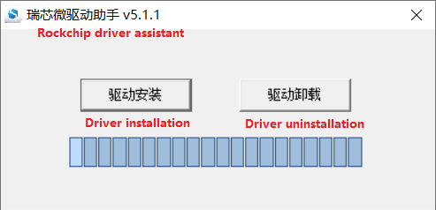
Click Install Driver.
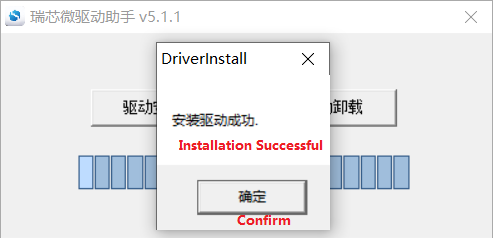
6.1.2 Complete OTG Flashing
6.1.2.1 RKDevTool Flashing Test
Path: OK1126B-C (Linux) User Data\Linux\Tools RKDevTool_Release_v3.37.zip
This is a development tool provided by Rockchip. Before use, unzip it into a directory with an all-English path, connect the development board to the host computer using a Type-C cable, hold down the UPDATE button on the development board without releasing it, then press the RESET button once to reset the system; release the UPDATE button approximately two seconds later. The Rockchip development tools will display a message indicating that a MASKROM device has been detected.
Note:
The device identification process takes place whilst the UPDATE button is held down when the development board is powered on;
The extraction directory for Rockchip’s development tools can be arbitrary, but users have reported that the directory should contain only English characters. If the development tool interface does not match the image shown below, consider extracting it to a directory with only English characters;
When performing OTG flashing, two things must be noted: Connect the OTG cable. OTG and USB3.0 are multiplexed, so the DIP switch must be adjusted.
Open the Rockchip development tool:
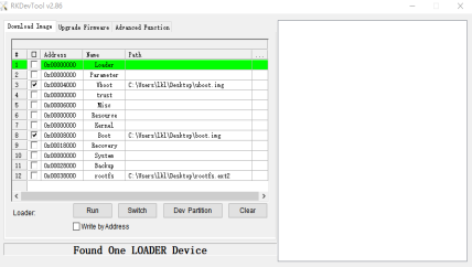
Click the “Upgrade Firmware” tab, click the “Firmware” button to select the full upgrade image update.img. The programme will analyse the firmware, so please wait a moment.
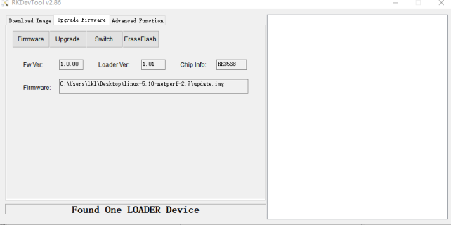
Click the “Upgrade Firmware” button -> “Upgrade” to begin upgrading.
6.1.2.2 FactoryTool Flashing Test
FactoryTool is used for batch OTG flashing in the factory. It does not require reading an image file and can batch-flash large images. If RKDevTool does not meet compatibility requirements, this method can also be attempted. Before using, extract it to a directory with only English characters. Connect the development board and host using a Type-C cable. Press and hold the UPDATE+ button, press the reset button for the system reset, and after about two seconds, release the UPDATE+ button. The Rockchip development tools will display a message indicating that a MASKROM device has been detected.
Note:
The device identification process takes place whilst the UPDATE button is held down when the development board is powered on;
The extraction directory for Rockchip’s development tools can be arbitrary, but users have reported that the directory should contain only English characters. If the development tool interface does not match the image shown below, consider extracting it to a directory with only English characters.
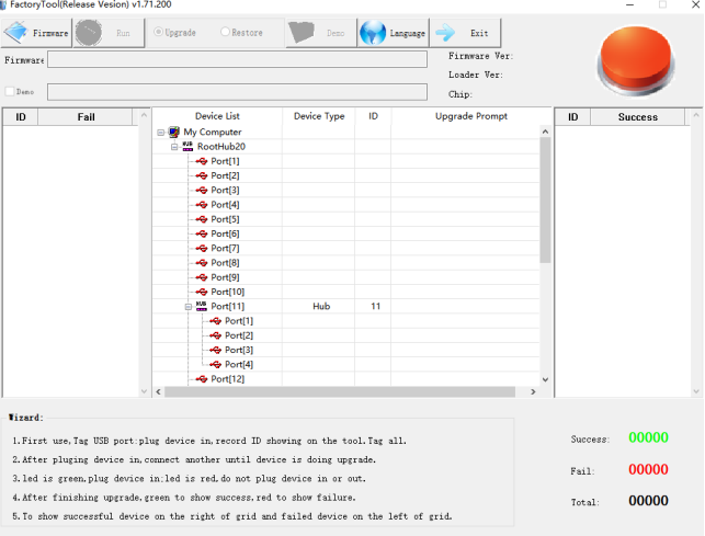
Click to select the firmware, then click “Start”; the system will automatically begin flashing the MASKROM device once it has been detected.
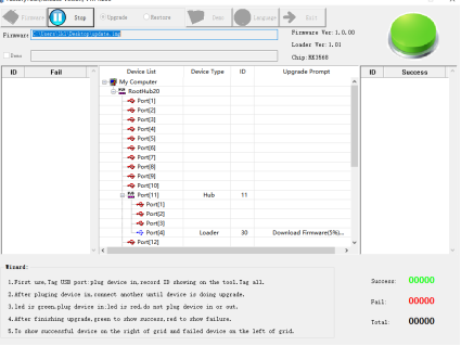
Downloading firmware:
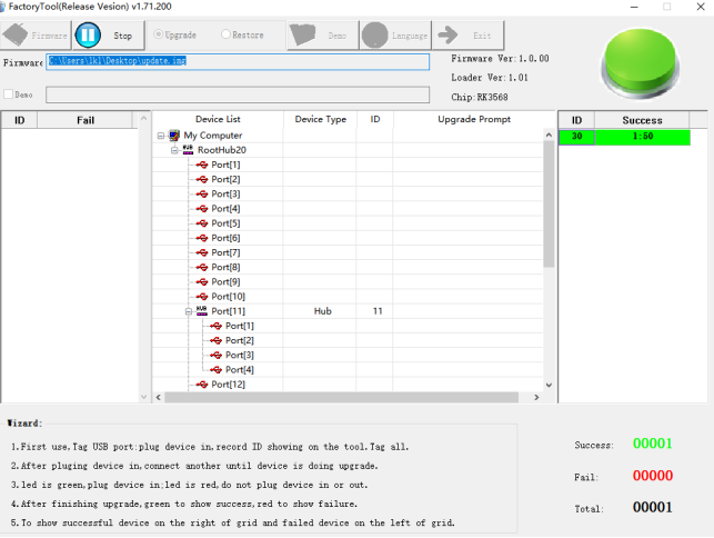
Upgrade successful. The system will not automatically restart and will require a power cycle to restart.
6.1.3 OTG Step-by-Step Flashing Test
During the development phase, performing full flashing every time can be time-consuming. Therefore, here it introduces how to use OTG flashing tools to flash individual partitions.
Note: The device identification process takes place whilst the UPDATE button is held down when the development board is powered on.
Firstly, once the OK1126B- C-linux-release build has completed, you will find a separate partition image in the rockdev directory.
Take separate flashing boot. img (including device tree and startup logo) as an example to show the flashing method.
Connect the development board to the host computer using a Type-C cable. Once the development board has booted, run reboot loader, or hold down Ctrl+D whilst powering on until the system prompts that a LOADER device has been detected.
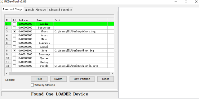
Click the “Device Partition Table” button to automatically read the partition . address.
It will ask if you want to update the download address. Click “Yes,” and the partition table will be read successfully.
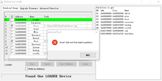
Click the area to the right of the partition to select the partition image, and tick the partition.
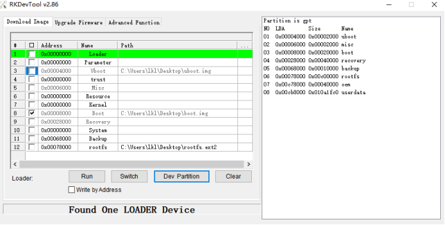
Click the “Execute” button to automatically flash and restart.
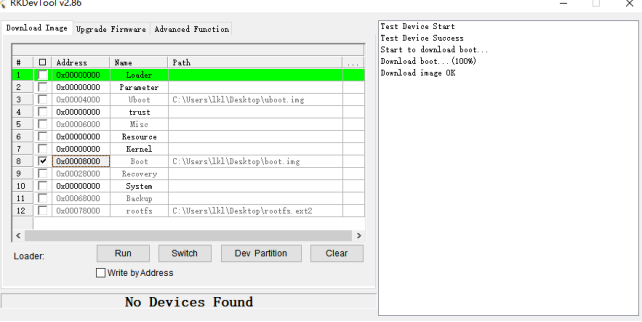
MASKROM Mode Introduction
If Loader mode is inaccessible (loader problem, etc.), press and hold the UPDATE key, then press the reset key to enter maskrom mode for flashing.
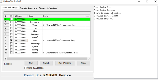
At this point, the system will display a message indicating that a MASKROM device has been detected; the flashing procedure is the same as for LOADER mode, and it is best to use update.img for flashing.
Note: Don’t click “Device Partition Table” in maskrom mode, it is invalid.
6.2 TF System Flashing
TF card making and testing.
Note: Testing indicates that the maximum supported TF card capacity is 16 GB. Using a TF card of 32 GB or larger may result in flashing failure.
Copy SDDiskTool_v1.78.zip from the user profile tool directory to any windows directory. Run SD_Firmware_Tool.exe with administrator privileges.
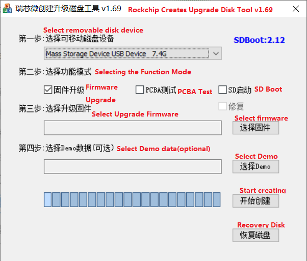
Select the disk device, tick the “Firmware Update” box, and select update.img. Click to start creating.
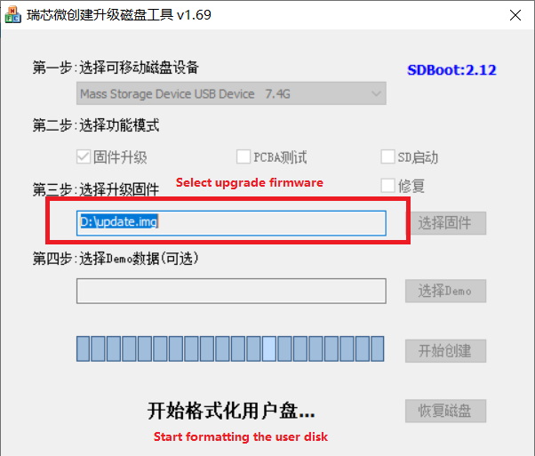
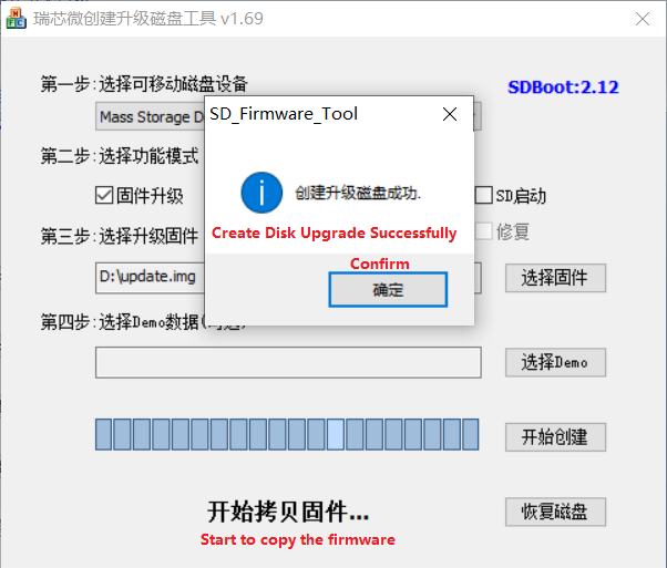
Insert the TF card into the development board and power it on; the system will automatically begin the flashing process. Once the flashing is complete, both the screen and the serial port will display the following message:
Please remove SD CARD!!!, wait for reboot.
At this point, remove the TF card and the system will restart automatically (please do not switch off the power directly).
If the device does not restart automatically after removing the TF card, you can complete the flashing process by restarting it manually. As shown in the figure above, the burning process takes about 7 minutes. Please wait patiently during the burning process.