Android16.0_User’s Manual_V1.0
Document classification: □ Top secret □ Secret □ Internal information ■ Open
Copyright
The copyright of this manual belongs to Baoding Folinx Embedded Technology Co., Ltd. Without the written permission of our company, no organizations or individuals have the right to copy, distribute, or reproduce any part of this manual in any form, and violators will be held legally responsible.
Forlinx adheres to copyrights of all graphics and texts used in all publications in original or license-free forms.
The drivers and utilities used for the components are subject to the copyrights of the respective manufacturers. The license conditions of the respective manufacturer are to be adhered to. Related license expenses for the operating system and applications should be calculated/declared separately by the related party or its representatives.
Overview
This manual is designed to help you quickly familiarize yourselves with the product, understand interface functions, and learn testing methods. It primarily covers the testing of development board interface functions, methods for flashing the image, and troubleshooting common issues encountered during use. During testing, certain commands have been annotated for better understanding, focusing on practicality and adequacy. For kernel compilation, related application compilation methods, and development environment setup, please refer to the “OK3572-C_Android16_User’s Compilation Manual” provided by Forlinx..
There are five chapters:
Chapter 1. is an overall overview of the product, briefly introducing the development board’s interface resources, related driver paths in the kernel source code, and explanations of key parts in the documentation;
Chapter 2. mainly focuses on the quick startup of the product, which can be achieved through serial port login and the introduction of the uboot menu;
Chapter 3. mainly involves testing the Android functionality of the product;
Chapter 4. Explains methods for updating the system image to storage devices, allowing users to choose the appropriate flashing method based on their needs.
Chapter 5. mainly covers the OTA upgrade testing of the product system.
Additionally, the manual includes explanations of some symbols and formats.
Format |
Meaning |
|---|---|
Note |
Note or particularly important information must be read carefully. |
📚 |
Relevant explanations regarding the testing section |
️️🛤️ ️️ |
Related paths. |
Blue font on gray background |
Refers to the command entered on the command line, which needs to |
Black font on a gray background |
Serial output information after command input |
Black Bold font on a gray background |
Key information in the serial output: |
// |
Explanation of input commands or output information: |
Username@Hostname |
console: Account details for logging into the development board’s serial port; |
Example: Checking the Loading Status of the AW9098 Module Driver:
forlinx@ubuntu:~/3572$ ls                   //List the files in this directory
OK3572-android-source  OK3572-android-source.tar.bz2
forlinx@ubuntu: The username is forlinx, and the hostname is ubuntu, indicating that the operation is being performed in the development environment on Ubuntu.
//: Denotes explanatory notes about commands or printed information; no input required.
Ls: Blue font with gray background, indicating the relevant command that needs to be entered manually.
OK3572-android-source: Text with gray background and black font represents the output after entering the command. Bolded text indicates key information, showing in this case that the module driver has been loaded.
Application Scope
This software manual is designed for the OK3572-C platform running Android16. While other platforms may also reference this manual, there could be differences that require adjustments for the specific use.
Notes on the Data
The OK3572-C development board is attached with the software data of the Android operating system. This is a user manual for Android users. It tests and describes the relevant functions of the Android 16 kernel. Please select the data consistent with the image in the development board for operation. You can access software and hardware documentation through the cloud storage link provided by our company (please ask your sales representative for the download link).
The default programming of OK3572-C development board is Linux system. Please reprogram the Android image before operation. Refer to Chapter 4 “Flashing System” for the programming method. After the programming is completed, you can view the kernel version information through the steps in “Serial Login”.
For detailed information, please refer to the OK3572-C User Materials. All file paths for user materials mentioned in this document are relative to the root directory of the OK3572-C User Materials.
Revision History
Date |
Version |
SoM Version |
Carrier Board Version |
Revision History |
|---|---|---|---|---|
26/06/2026 |
V1.0 |
V1.0 |
V1.0 and above |
OK3572-C_Android16 User’s Manual Initial Version. |
1. OK3572 Development Board Description
The RK3572 is a low-power, high-performance processor based on the ARM64 architecture. It comprises four Cortex-A73 cores and four Cortex-A53 cores, as well as a dedicated NEON coprocessor and a neural network processing unit (NPU), and is suitable for use in computers, mobile phones, personal mobile internet devices and digital multimedia devices.
Connection method: Board-to-board.
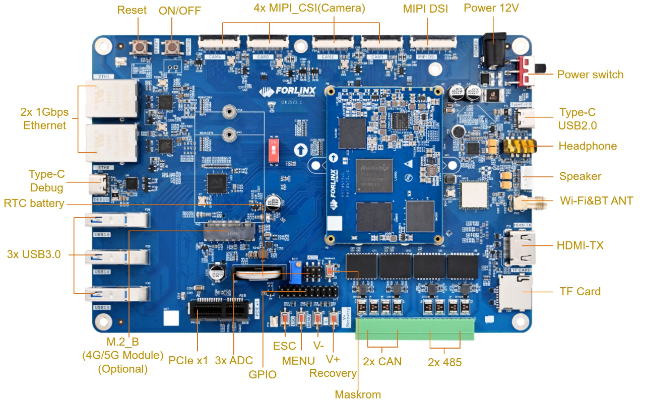
Front
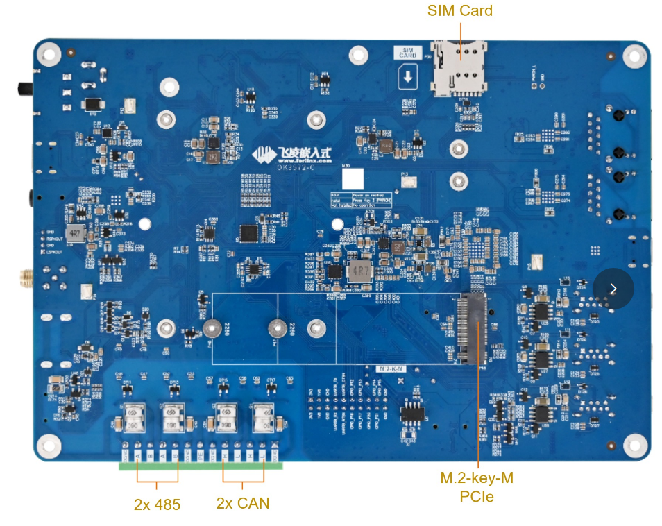
Back
The OK3572-C model with 2GB of RAM does not currently support Android 16.
Note: Hardware specifications are not covered in this software manual. Before development, please refer to the “User’s Hardware Manual”( Software Documentation) to understand the product naming and hardware configuration.
1.1 Android16 System Software Resources
Device |
Driver Source Code Location in the Kernel |
Device Name |
|---|---|---|
LCD Backlight Driver |
drivers/video/backlight/pwm_bl.c |
/sys/class/backlight |
USB Interface: |
drivers/usb/storage/ |
|
USB Mouse |
drivers/hid/usbhid/ |
/dev/input/mice |
Ethernet |
drivers/net/ethernet/stmicro/stmmac |
|
SD/micro TF card driver |
drivers/mmc/host/dw_mmc-rockchip.c |
/dev/block/mmcblk1pX |
EMMC Driver |
drivers/mmc/host/dw_mmc-rockchip.c |
/dev/block/mmcblk2pX |
OV13855 |
drivers/media/i2c/ov13855.c |
/dev/videoX |
OV5645 |
drivers/media/i2c/ov5645.c |
/dev/videoX |
LCD controller |
drivers/gpu/drm/rockchip/rockchip_drm_vop.c |
|
MIPI CSI |
drivers/phy/rockchip/phy-rockchip-mipi-rx.c |
|
MIPI DSI |
drivers/phy/rockchip/phy-rockchip-inno-mipi-dphy.c |
|
LCD touch driver |
drivers/input/touchscreen/gt9xx/*drivers/input/touchscreen/edt-ft5x06.c |
/dev/input/eventX |
RTC Real - Time Clock |
drivers/rtc/rtc-rx8010.cdrivers/rtc/rtc-pcf8563.c |
/dev/rtc0 |
Serial Port |
drivers/tty/serial/8250/8250_dw.c |
/dev/ttySX |
Button driver |
drivers/input/keyboard/adc-keys.c |
/dev/input/eventX |
LED |
drivers/leds/leds-gpio.c |
|
I2S |
sound/soc/rockchip/rockchip_i2s.c |
|
Audio Driver |
sound/soc/codecs/rk817_codec.c |
/dev/snd/ |
PMIC |
drivers/mfd/rk808.c |
|
PCIE |
drivers/pci/controller/pcie-rockchip.c |
|
Watchdog |
drivers/watchdog/dw_wdt.c |
|
SPI |
drivers/spi/spi-rockchip.c |
|
PWM |
drivers/video/backlight/pwm_bl.c |
1.2 eMMC Storage Partition Table
The table below shows the eMMC storage partition information for the Android operating system (calculated using a block size of 512 bits):
Partition Index |
Name |
Offset/Block |
Size/Block |
Content |
|---|---|---|---|---|
N/A |
security |
0x00000000 |
0x00002000 |
MiniLoaderAll.bin |
1 |
uboot |
0x00002000 |
0x00004000 |
uboot.img |
2 |
misc |
0x00006000 |
0x00008000 |
misc.img |
3 |
dtbo |
0x0000e000 |
0x000a000 |
dtbo.img |
4 |
vbmeta |
0x00018000 |
0x000c000 |
vbmeta.img |
5 |
boot |
0x00024000 |
0x000e000 |
boot.img |
6 |
recovery |
0x00032000 |
0x000f000 |
recovery.img |
7 |
backup |
0x00041000 |
0x00100000 |
backup.img |
8 |
cache |
0x00141000 |
0x00110000 |
cache.img |
9 |
metadata |
0x00251000 |
0x00120000 |
metadata.img |
10 |
frp |
0x00371000 |
0x00140000 |
frp.img |
11 |
baseparameter |
0x004b1000 |
0x00150000 |
baseparameter.img |
12 |
super |
0x00601000 |
0x00160000 |
super.img |
13 |
userdata |
0x00761000 |
0x00811400 |
userdata.img |
2. Fast Startup
2.1 Preparation Before Startup
The OK3572 development board supports serial port login.
Hardware Preparation:
12V2A or 12V3A DC power cable
Debugging Serial Cable (Serial Login Use)
The debug serial port on the development board is a Type-C port. You can connect the development board to a PC using a USB-A to Type-C cable to monitor the board’s status. Note: Do not insert a TF card when switching on the device, as this may cause the card to become unreadable.
2.2 Debugging Serial Port Driver Installation
The debugging serial port of OK3572 platform features Type-C interface (carrier board silk-screen DEBUG), with USB to UART chip on board. There is no need to purchase USB to serial port debugging tools. It is simple and convenient to use, and serial port drivers need to be installed. Adb, burning and other functions are realized through Type-C interface (carrier board silk-screen Type-C), and OTG related drivers need to be installed.
Serial driver file 3-Tool \ CP210x _ Windows _ Drivers. Zip.
OTG related driver “3-Tool \ DriverAssitant _ v5.14.zip”
2.3 Serial Port Login
2.3.1 Serial Connection Settings
Note:
Serial terminal login user: The serial terminal automatically logs in as the “root” user, with no password;
Settings: Baud rate 1500000, 8 data bits, 1 stop bit, no parity/flow;
Hardware Requirements: Type-C for connecting PC and development board;
Software Requirements:
A serial terminal application must be installed on the PC Windows. There are various terminal programs available, and you may choose any one you are familiar with.
Take putty as an example to introduce the setting mode of the putty terminal:
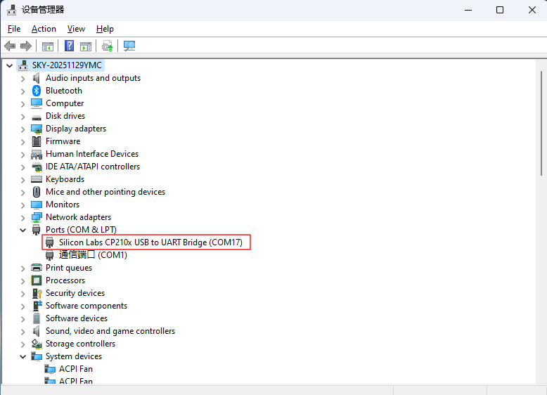
Step 1: Confirm the serial port number connected to the computer, checking the port number in Device Manager, based on the actual port recognized by the computer;
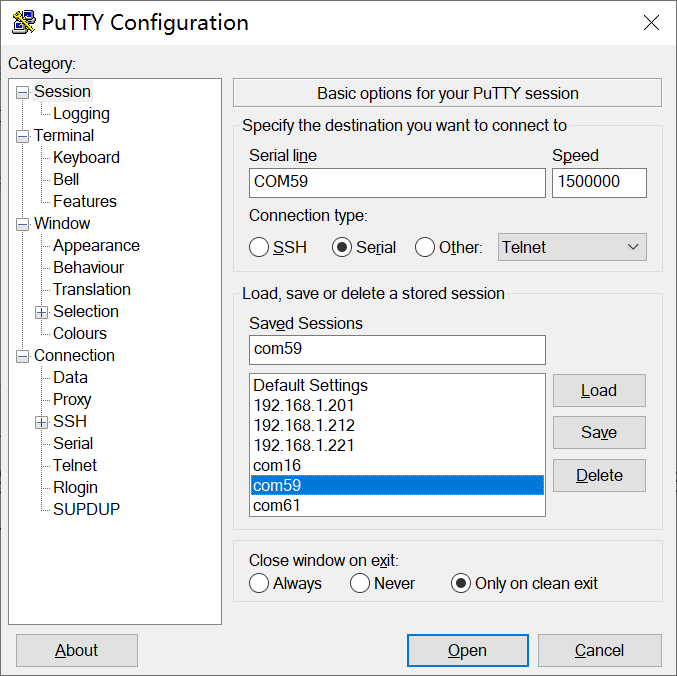
Step 2: Configure PuTTY: Open PuTTY. In the “Serial line” field, enter the identified COM port and set the baud rate to 1500000;
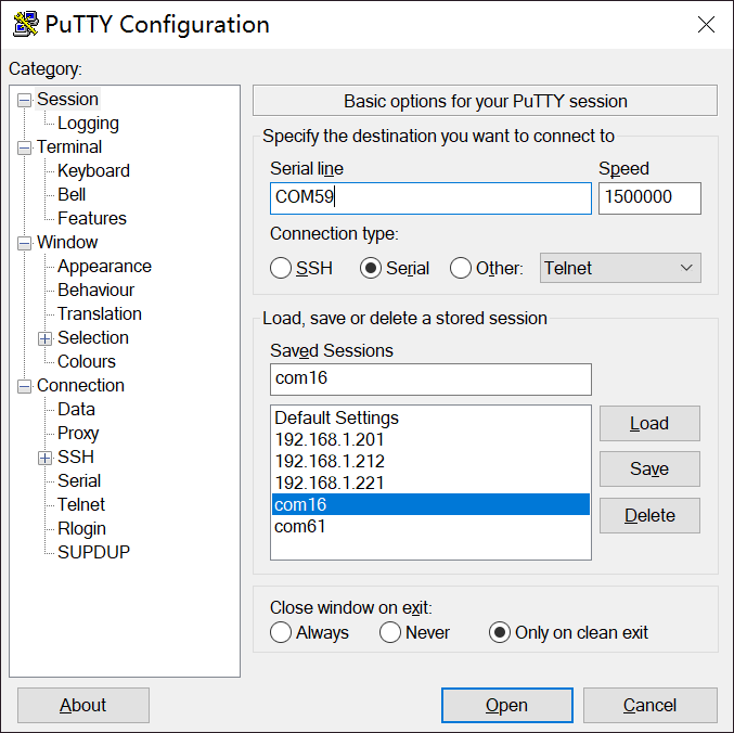
Step 3: After completing the above settings, enter the COM port number used by your computer in the “Saved Sessions” field (as shown in the following figure, using COM59 as an example), and save the configuration. Subsequently, when reopening the serial port, simply click the saved port number to directly apply the settings.
2.3.2 Serial Port Login
After the PC terminal software is configured, connect the PC and the development board using a serial cable, then power on the device after connecting the power supply. The startup information can be viewed through the terminal software.
2.5 System Shutdown
In general, you can directly power off the system. However, if operations such as data storage or functional usage are in progress, avoid cutting power abruptly to prevent irreversible file damage, which may require re-flashing the firmware. To ensure all data is fully written, you can execute the sync command to complete data synchronization before powering off.
Shut down the Android system:
Press the “PWRON” and “V+” buttons simultaneously, or long-press “PWRON” and then tap “Shutdown”.
Long-pressing “PWRON” for 6 seconds will force a power-off.
Note: For products designed based on the SoM:, if unexpected power loss during use leads to system abnormalities, consider implementing measures such as power-loss protection in the design.
3. Android Function Usage and Testing
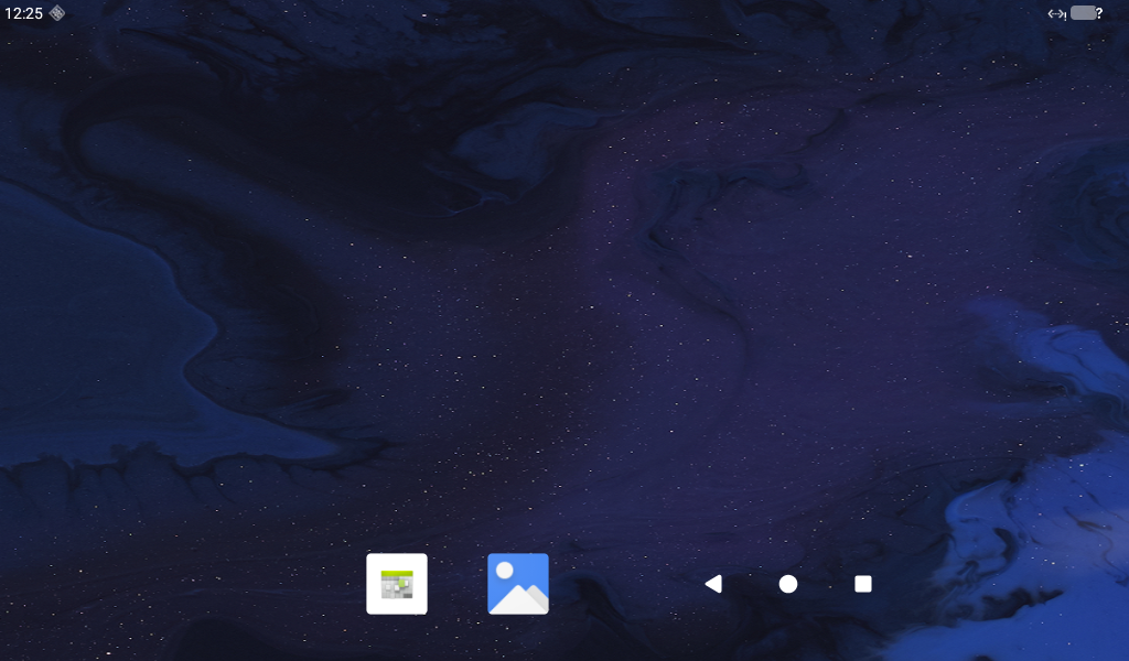
3.1 Home Screen Display
3.2 App Drawer
Swipe up on the home screen to display the following interface.
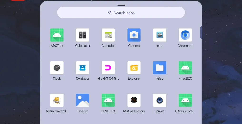
Note: There may be minor differences after a software version update. The provided images are for reference only and do not represent the exact interface for every subsequent version update.
3.3 Setting the Language
Open the “Settings” app from the App Drawer and tap “System”.
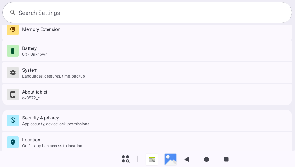
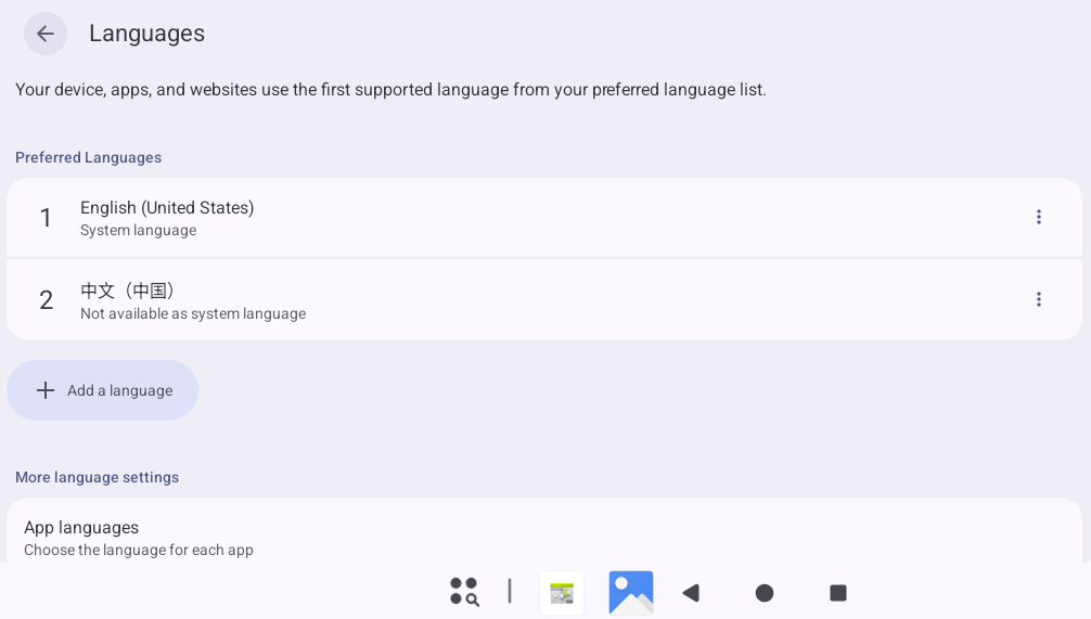
Tap “Languages & input” to enter the language settings interface.
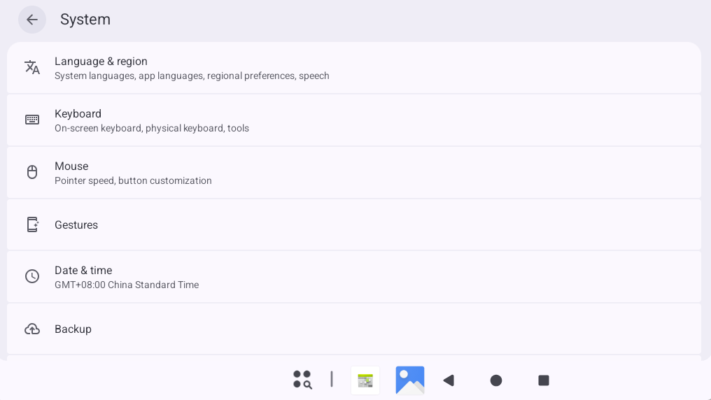
Here, you can select the desired language to set.
3.4 Viewing Images and Videos
Save the image and video files you wish to browse onto a TF card and insert the TF card into the development board.
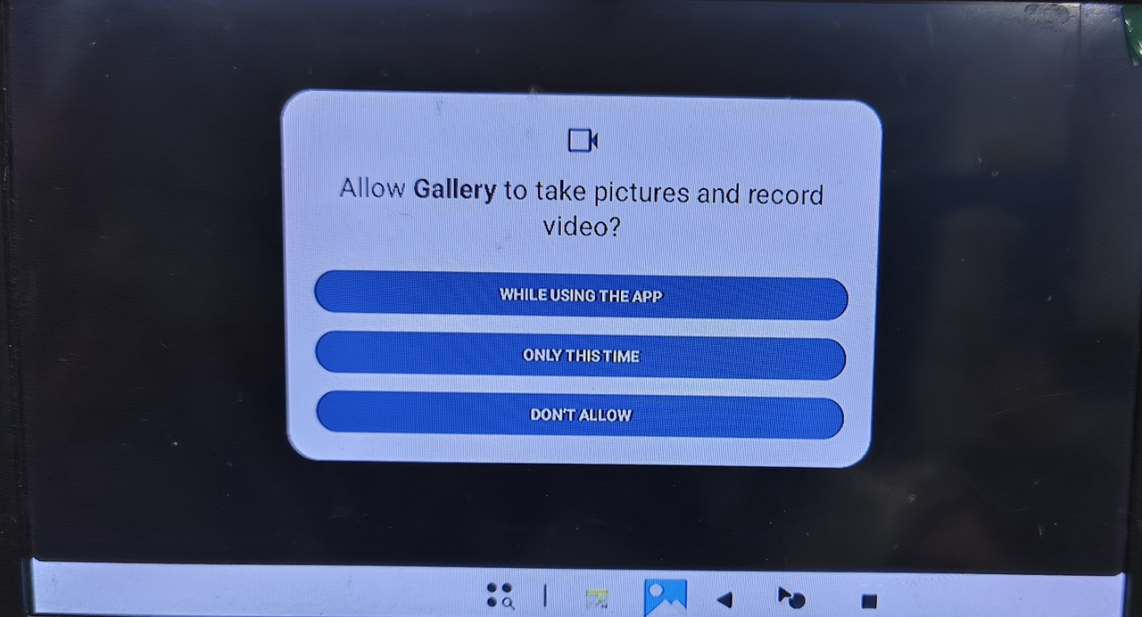
Open the “Gallery” app from the App Drawer.
Configure permissions as needed.
3.5 Audio Test
Save the audio files you wish to play onto a TF card and insert the TF card into the development board.
Open the “Music” app from the App Drawer.
Tap “Songs” on this interface to enter the song list interface.
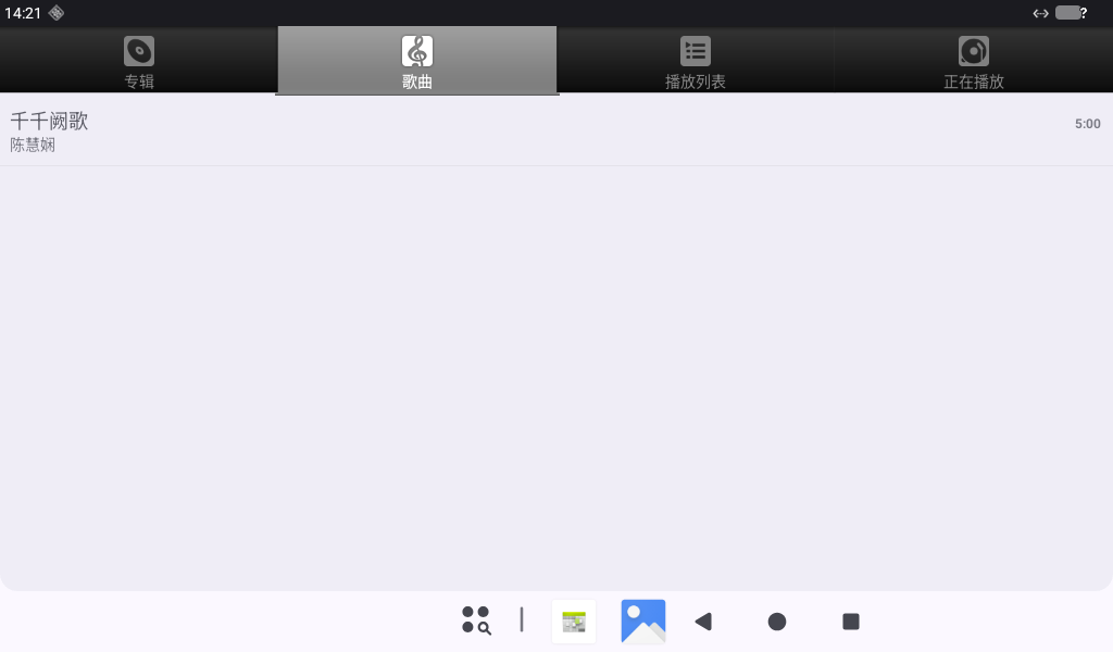
Tap to play music, entering the playback interface.
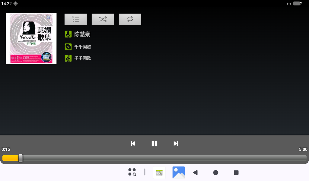
You can adjust the volume using the physical VOL+ and VOL- buttons on the development board’s carrier board.
3.6 Audio Recording (Supports Mic Input)
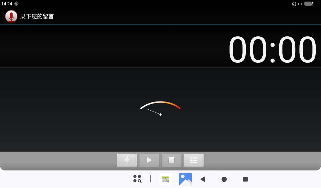
Open the “Recorder” app from the App Drawer.
Tap the “Circle button” to start recording. (Note: The indicator will swing according to sound levels during normal recording.)
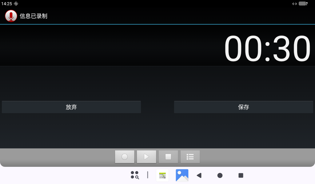
Tap the “Square button” to stop recording, then finally tap the “Save” button to save the recording.
Tap the “ ” at the bottom to display previously recorded audio files.
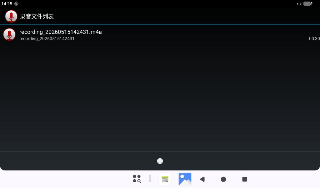
Tap the audio file you want to play to start playback.
3.7 Adjusting Volume
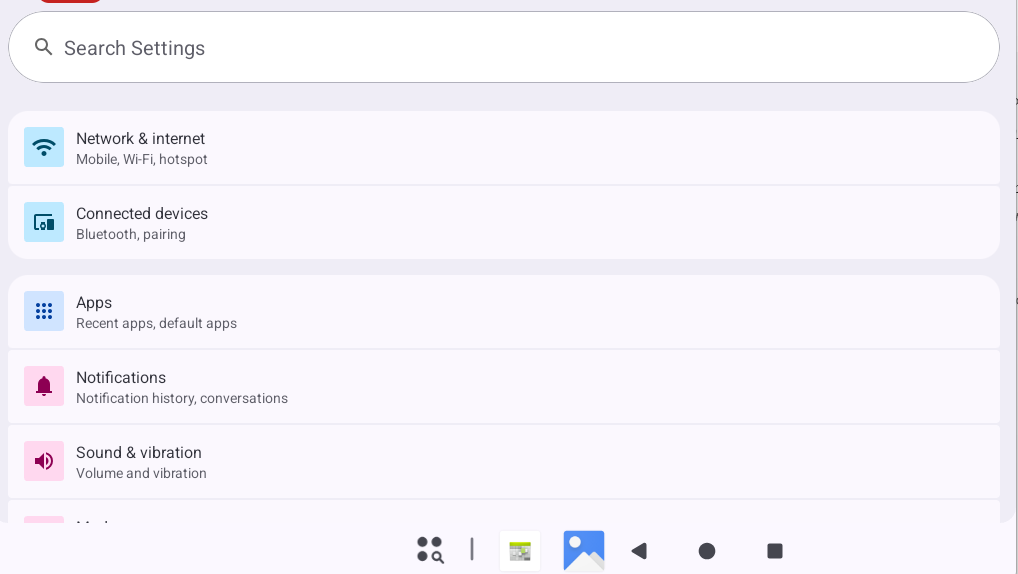
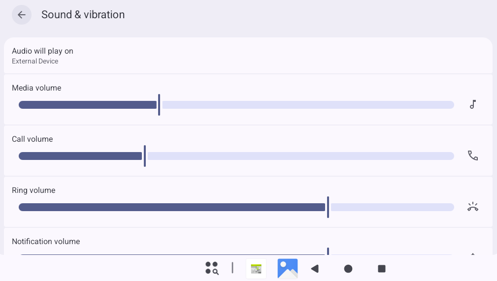
Open the “Settings” app from the App Drawer, tap “Sound & vibration” to enter the volume settings interface.
On this interface, you can adjust the volume for various parts and also use the physical VOL- and VOL+ buttons on the baseboard to adjust media volume.
3.8 Display Settings
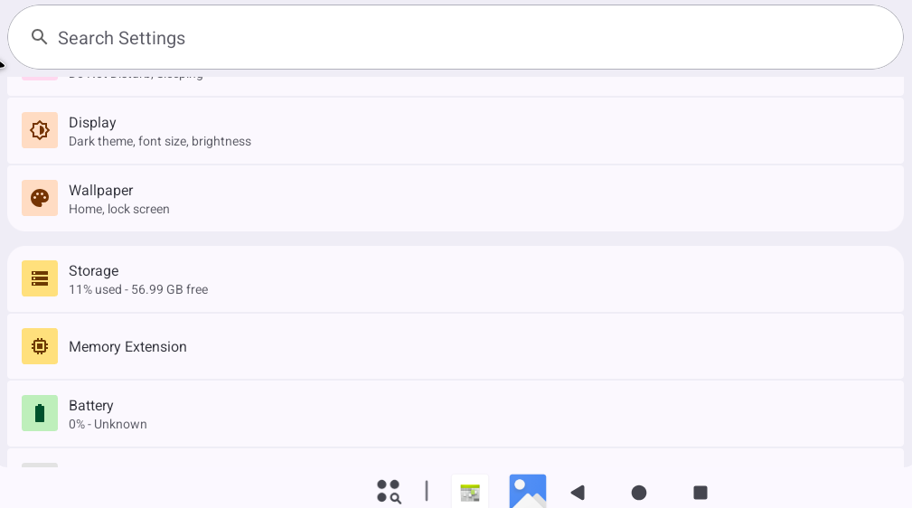
Open the “Settings” app from the App Drawer, tap “Display” to enter the display settings interface.
Tap “Brightness” to adjust the MIPI screen brightness.
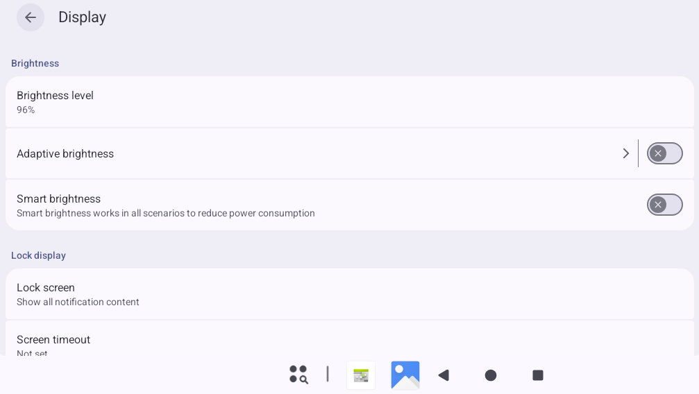
The OK3572 is set to “Never” for screen timeout by default. If you need the screen to turn off automatically, tap “Screen timeout” and select a duration.
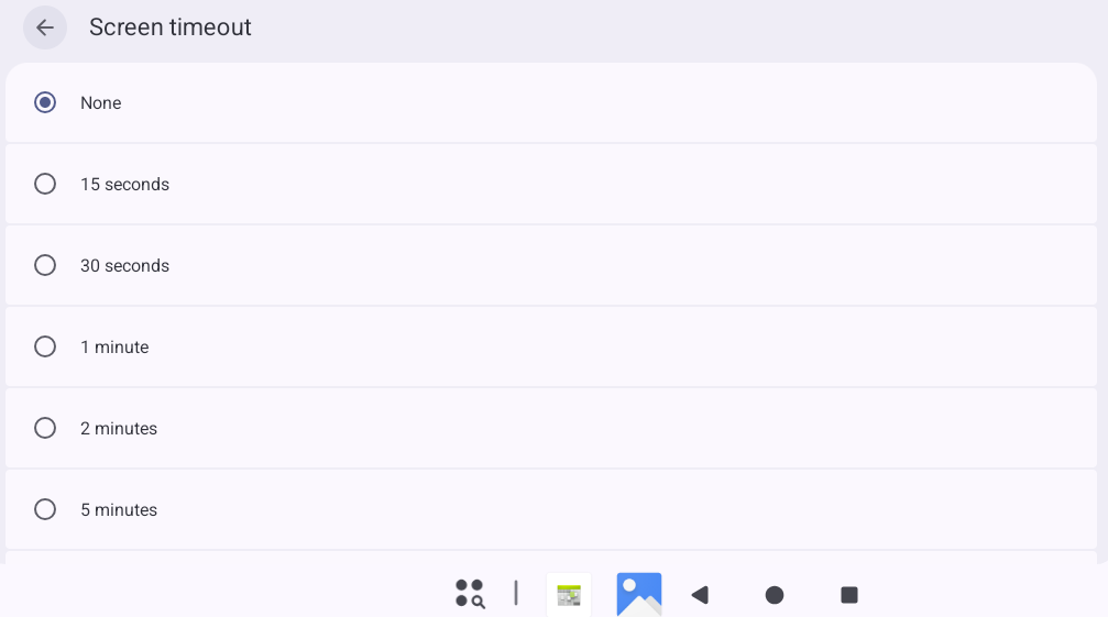
If there is no operation on the interface within the set timeout period, the screen will enter sleep mode. A short press of the “PWRON” button on the baseboard will wake the screen.
3.9 Setting Time (RTC)
Open the “Settings” app from the App Drawer and tap “System”.
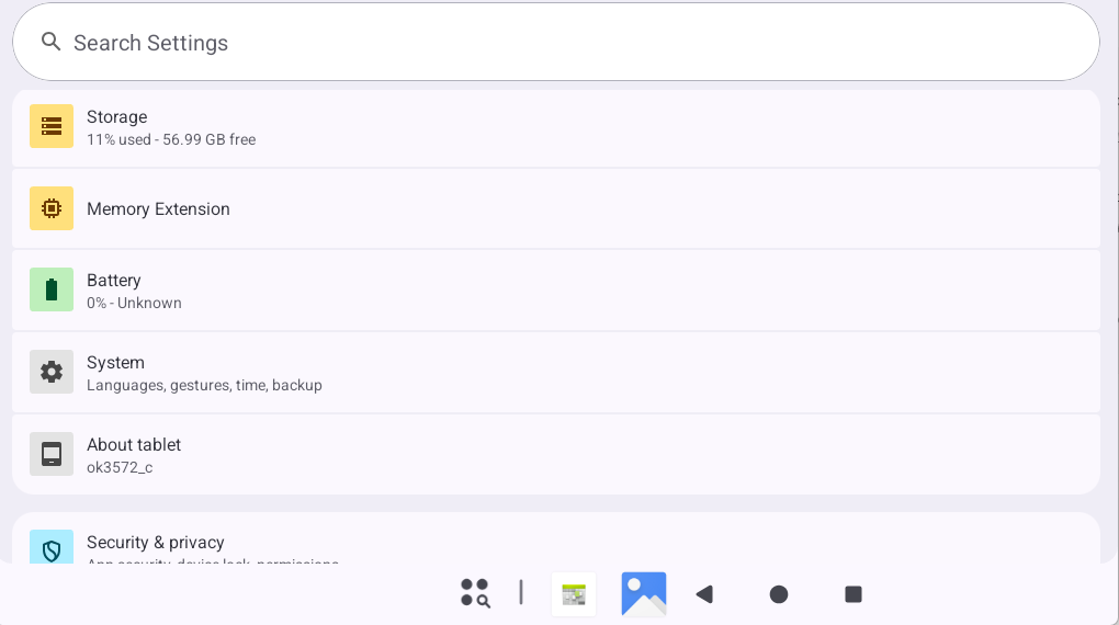
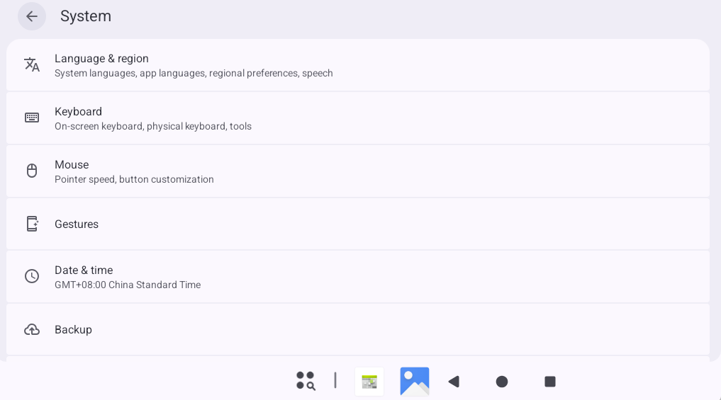
Tap “Date & time”.
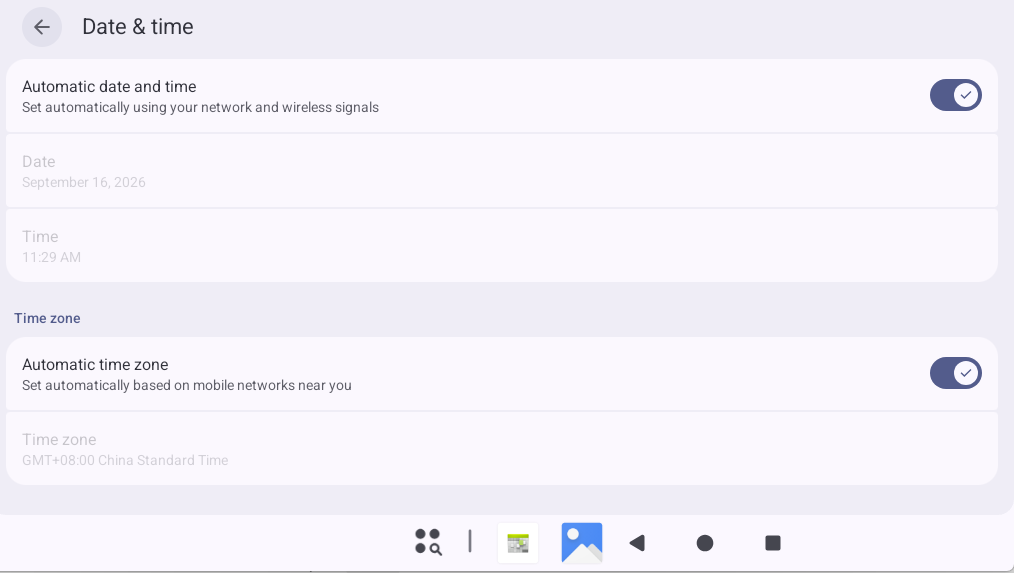
Turn off “Automatic date & time” to use the RTC time. Here you can change the date and time, and the time will remain synchronized and updated after a power cycle (ensure the coin cell battery is installed).
3.10 Ethernet Test
The OK3572 board features two onboard Gigabit Ethernet ports (Ethernet ETH0 and Ethernet ETH1). Additional network cards can be extended via PCIe.
Note: Network priority: Ethernet > Wi-Fi > Mobile Network.
After inserting an Ethernet cable, open the “Settings” app from the App Drawer and tap “Network & internet”.
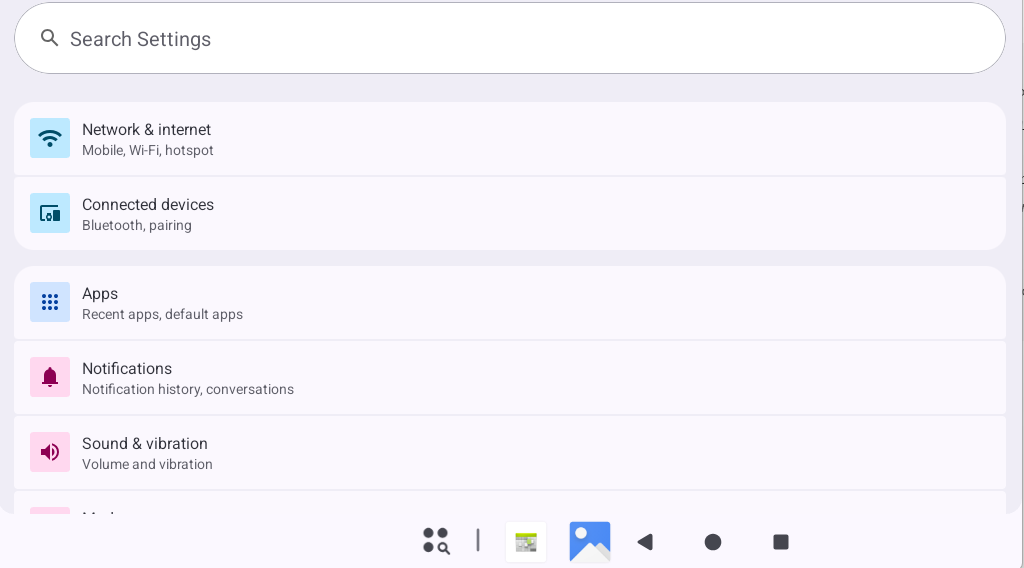
Tap “Ethernet”.
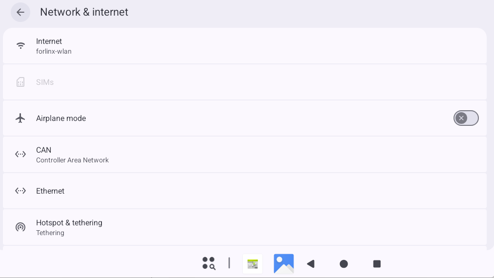
The default IP acquisition method is “DHCP”.
To set a static IP, tap “Ethernet IP mode” and select “Static” to configure a static IP (IPv4 only).
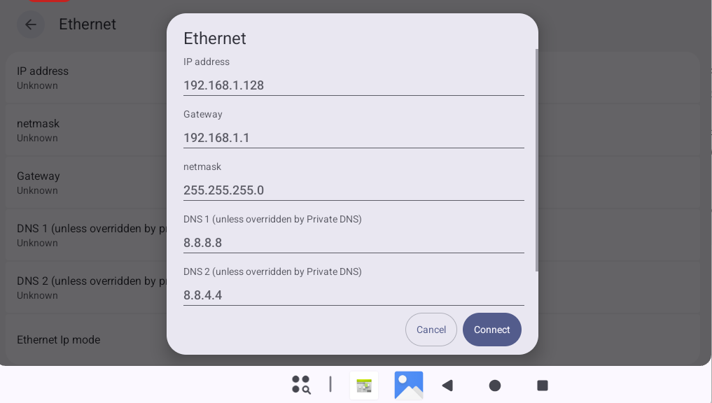
Tap “Connect” to complete the configuration.
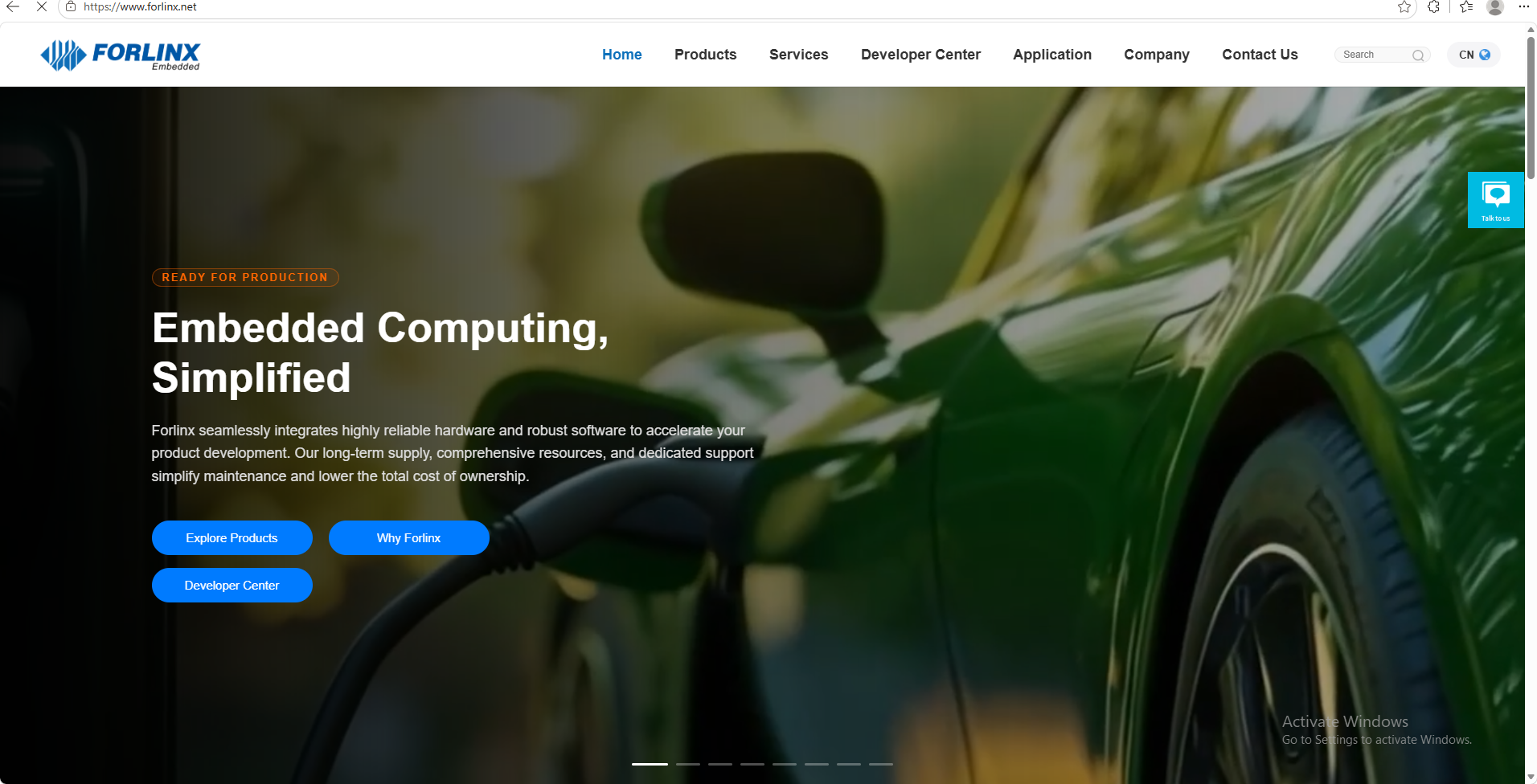
After a successful connection, open the “Chromium” app from the App Drawer.
Enter www.forlinx.net in the address bar to test the network.
3.11 WiFi Test
Note:
Network priority: Ethernet > Wi-Fi > Mobile Network;
When testing Wi-Fi, remove the Ethernet cable.
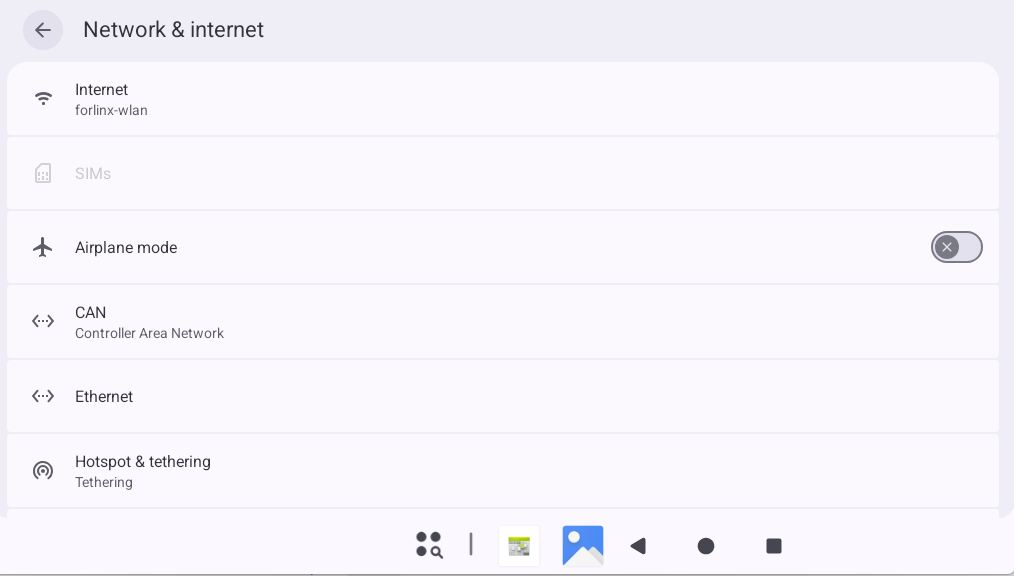
Open the “Settings” app from the App Drawer and tap “Network & internet”.
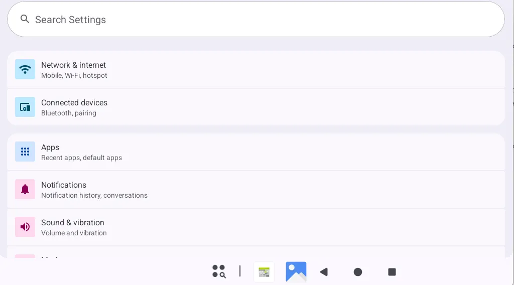
Tap “Internet”.
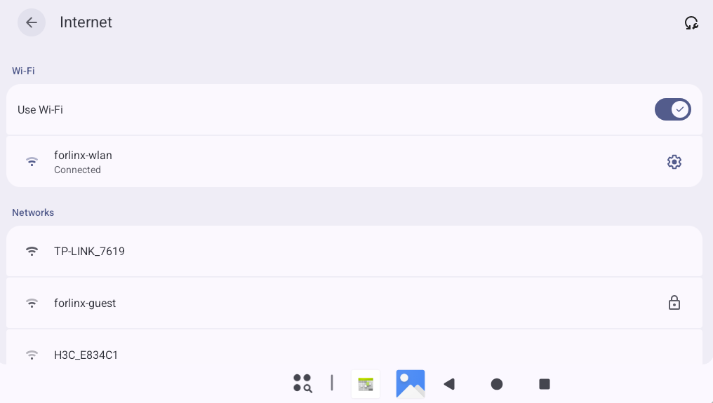
Turn on the “Wi-Fi” switch, select an SSID, and enter the password.
After a successful connection, open the “Chromium” app from the App Drawer.
Enter www.forlinx.net in the address bar to test the network.
3.12 WiFi Hotspot Test
The OK3572 supports sharing an Ethernet or mobile network connection via Wi-Fi, enabling Wi-Fi hotspot functionality. First, connect an Ethernet cable to ensure normal Ethernet connection.
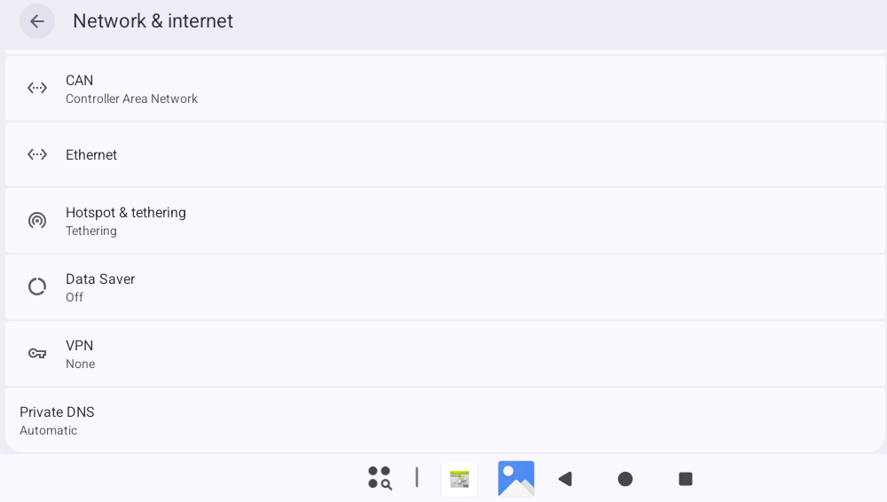
Open the “Settings” app from the App Drawer and tap “Network & internet”.
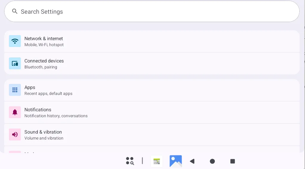
Tap “Hotspot & tethering”
Tap “Wi-Fi hotspot”.
Enable the Wi-Fi hotspot and set the hotspot name and password.
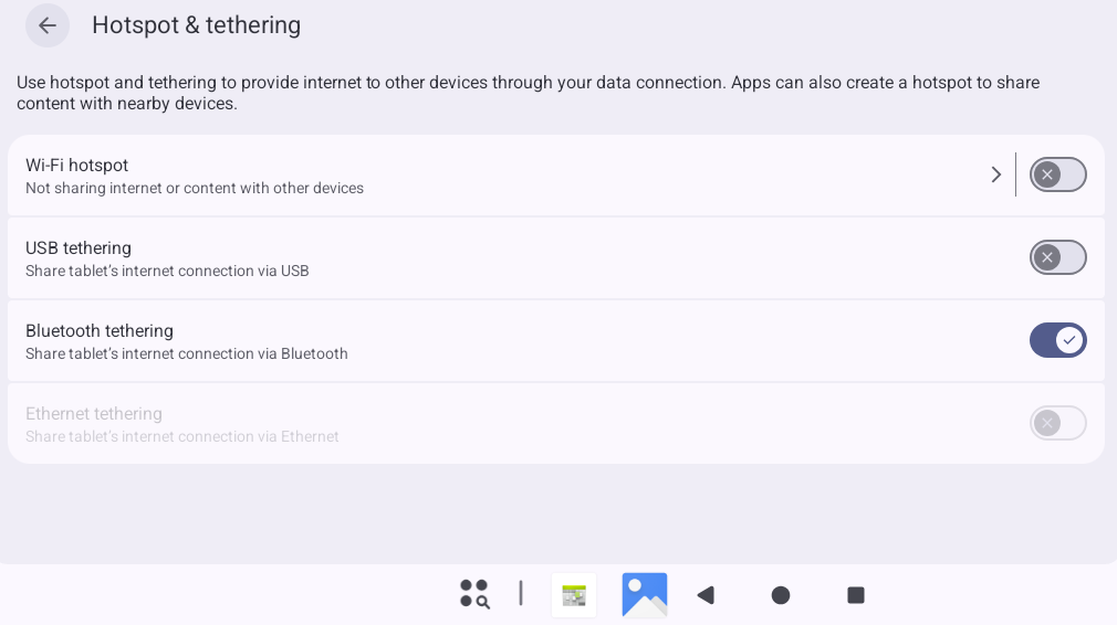
After a mobile phone connects to the hotspot, it should be able to access the internet normally.
3.13 4G/5G Module Test
Note:
Network priority: Ethernet > Wi-Fi > Mobile Network;
When using a 4G module, switch the S2 DIP switch to ON.
The OK3572 carrier board supports the 4G module (EM05) and the 5G module (RM500U). Before testing, power off the development board, insert the 4G/5G module with a SIM card (pay attention to the SIM card orientation), and then power on the board.
Open the “Settings” app from the App Drawer and tap “Network & internet”.
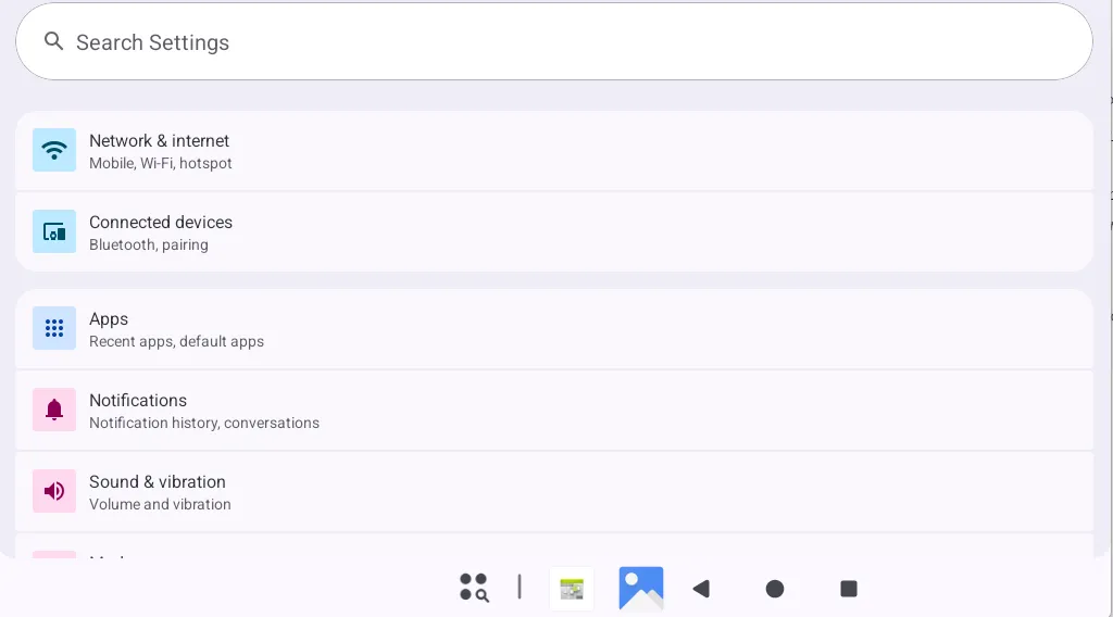
At this point, you should see a successful connection, for example, to “China Telecom”.
After a successful connection, open the “Chromium” app from the App Drawer.
Enter www.forlinx.net in the address bar to test the network.
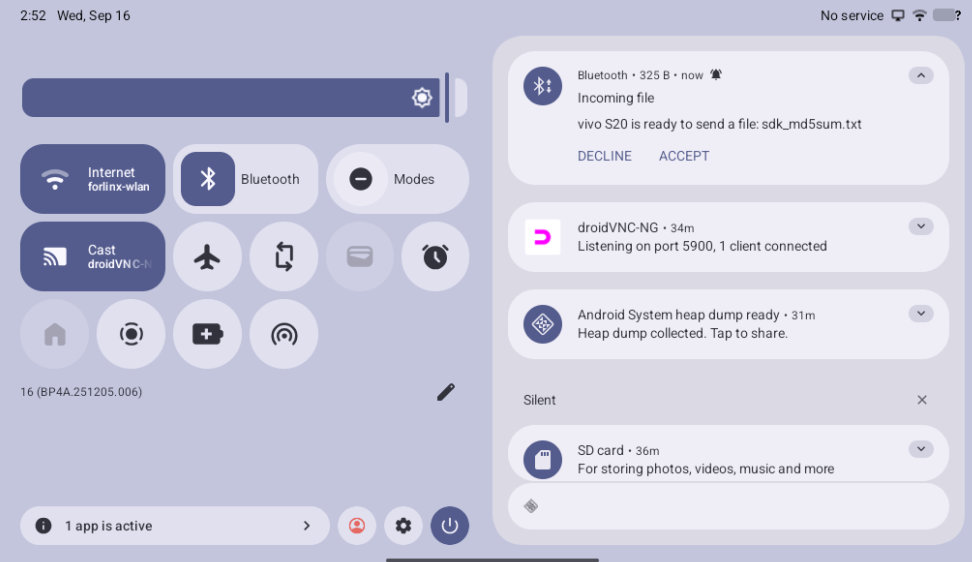
3.14 Bluetooth Testing
Note: The current system does not support iPhone Bluetooth connections.
The OK3572 platform’s Bluetooth function is tested using a WiFi & Bluetooth combo module, which supports acting as a host device to connect to Bluetooth peripherals.
Testing with a Bluetooth mouse is as follows:
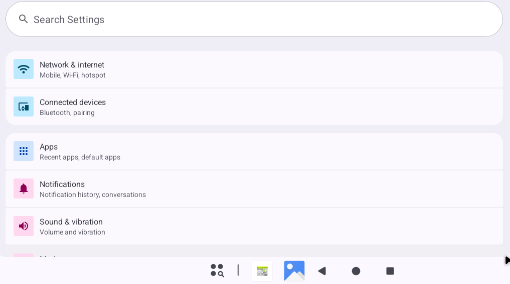
Open the “Settings” app from the App Drawer and tap “Connected devices”.
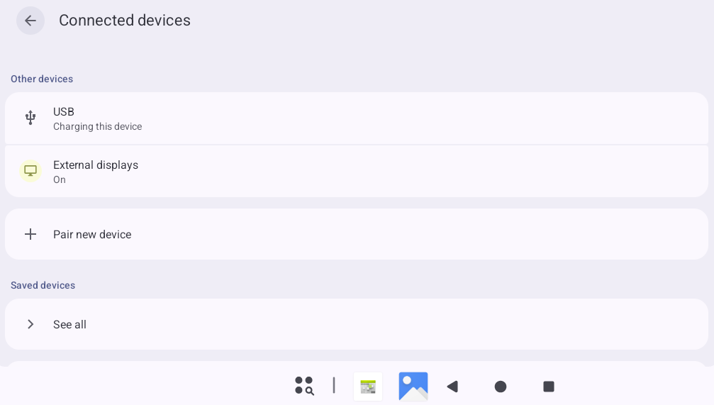
Tap “Pair new device”, and simultaneously put the Bluetooth mouse into pairing mode.
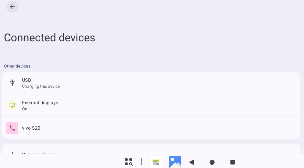
Tap the corresponding device name (e.g., the mouse).
Tap “Pair”.
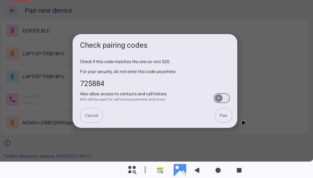
After a successful connection, proceed with file transfer or other operations.
3.15 Keypad Test (Sleep/Wake)
This development board features a total of 7 keys: VOL+, VOL-, MENU, ESC, PWRON, RESET, and Maskroom.
Button |
Function |
|---|---|
Recovery/VOL+ |
Volume Up |
VOL- |
Volume Down |
PWRON |
Sleep/Wake & Power On/Off |
Maskroom |
Enters Maskrom mode when pressed with RESET |
RESET |
Reset |
MENU |
Opens the main screen settings, widgets, and wallpaper menu. |
ESC |
Back |
By default, the board is set to not automatically sleep. A short press of the PWRON key will turn off the screen and put the system into sleep mode (note: do not connect any wake-up sources, such as USB OTG, to the bottom board during this test). The following log message indicates successful entry into sleep mode:
130|console:/sdcard $ [  498.148783][  T360] type=1400 audit(1778819566.832:195): avc:  denied  { sys_nice } for  comm="binder:709_3" capability=23

 scontext=u:r:hal_power_default:s0 tcontext=u:r:hal_power_default:s0 tclass=capability permissive=0

[  498.298714][  T408] rockchip-vop2 27500000.vop: [drm:vop2_crtc_atomic_disable] Crtc atomic disable vp1
[  498.317108][  T408] [WLAN_RFKILL]: wlan_early_suspend :enter
[  498.444878][  T155] rk3x-i2c 2c040000.i2c: timeout, ipd: 0x30, state: 3
[  498.444966][  T155] edt_ft5x06 2-0038: Unable to fetch data, error: -110
[  498.495054][ T2420] PM: suspend entry (deep)
[  498.501169][ T2420] Filesystems sync: 0.006 seconds
[  498.501354][ T2420] Freezing user space processes
[  498.509091][ T2420] Freezing user space processes completed (elapsed 0.007 seconds)
[  498.509146][ T2420] OOM killer disabled.
[  498.509155][ T2420] Freezing remaining freezable tasks
[  498.512506][ T2420] Freezing remaining freezable tasks completed (elapsed 0.003 seconds)
[  498.512583][ T2420] printk: Suspending console(s) (use no_console_suspend to debug)

INFO:    BL31: v2.12(release):v2.12.0-158-g9a419c7c9:derrick.huang, fwver: v1.05
INFO:    cfg=0x20608, times:1
INFO:    deep
INFO:    logoff
INFO:    PMU 32k
INFO:    dis_osc
INFO:    pmic_rk806
INFO:    wkup (0x100)
INFO:    io_ret (0x8)
INFO:    sleep_pin: 0x4 0x0
INFO:    pd(0xf061fff0 0x20006) idle(0x5f86ffc0 0x2000d)
INFO:    GPIO0_INT: 0xffff 0xffff 0xff9f 0xffff 0x0 0xd1126c9a
INFO:    GPIO1_INT: 0xffff 0xffff 0xffff 0xffff 0x0 0x810a0400
INFO:    GPIO2_INT: 0xffff 0xffff 0xffff 0xffff 0x0 0x3bcf01e0
INFO:    GPIO3_INT: 0xffff 0xffff 0xffff 0xffff 0x0 0xe0cbacf
INFO:    GPIO4_INT: 0xffff 0xff 0xffff 0xff 0x0 0xfe43fd
INFO:    IRQ_EN: 59 156 152 148 144 140 136 168 307 292
INFO:    IRQ_PED:
012
INFO:    pm_pmic_suspend 806[62, 63, 71, 7f]=(0x88, 0x8, 0x0, 0x0)
os 18/19 (0x100043c1, 0x30001001)
apvtm:
con0=0x23, con1=0x200
st0=0x1, st1=0x1d8
pvtm_freq: 22125khz, div = 94/0xffff
real_freq: 31khz
bcde3456789
PMU1_PWR(0x121 0x0) PMU1_CRU_PWR(0x42f 0x0) PMU1_WAKEUP_INT(0x100)
PMU2_BUS_IDLE_ST(0x5f86ffc0 0x2000d) PMU2_PWR_GATE_ST(0xf061fff0 0x20006)
PMU2_BUS_IDLE_CON(0x3f 0x2)
PMU2_PWR_GATE_CON(0xf 0x1)
PMU1_DDR_PWR_CON(0x23)
PMU1_PLLPD_CON(0x3ff)
PMU0_PWR(0x0) PMU0_WAKEUP_INT(0x0)
PMU0_DDR_RET(0x0 0x0) OS_REGS17(0x76543210)
PMU0GRF_SOC_CON0,1,5(0xc 0x600 0x64)
While in sleep mode, another short press of PWRON will wake the CPU. A long press of the PWRON key will power off the device.
The functions of other keys are straightforward and can be tested individually.
3.16 TF Card & USB Storage Test
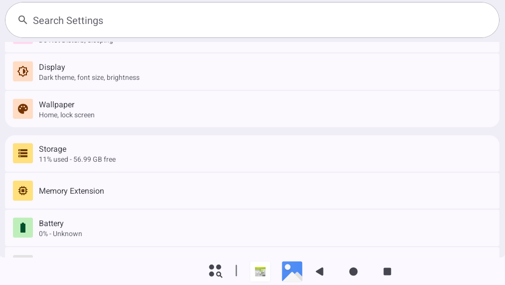
This section covers testing for TF cards and USB storage devices. The steps below use a TF card as an example.
From the app drawer, open the “Settings” app.
Tap on “Storage.”
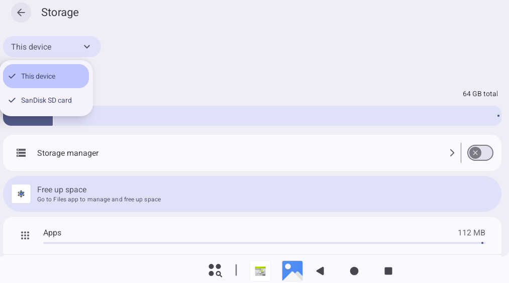
You can now view both the internal storage and any connected external storage devices.
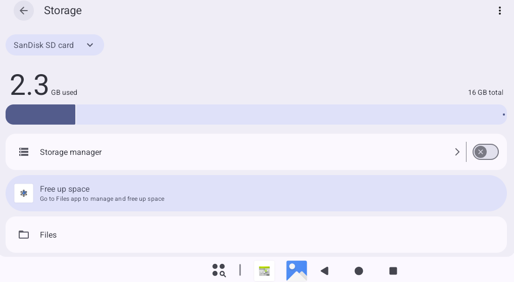
Select the TF card.
Tap “Files” to manage files on the TF card.
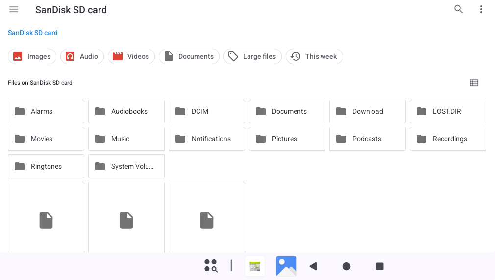
3.17 USB Mouse Test
After the system is running, connect a USB mouse to a USB Host port. A mouse cursor will appear on the interface, allowing you to operate the Android system with the mouse.
3.18 USB OTG Interface Test
The OK3572 development board supports the USB OTG function.
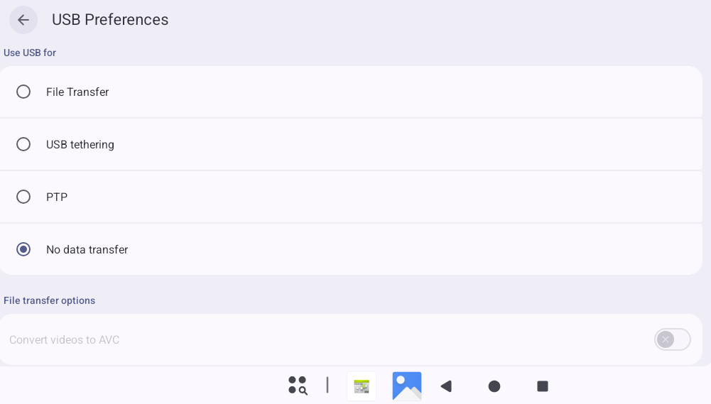
Connect the board to a computer using the Type-C port.
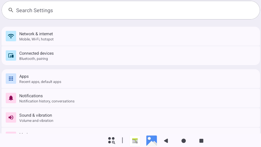
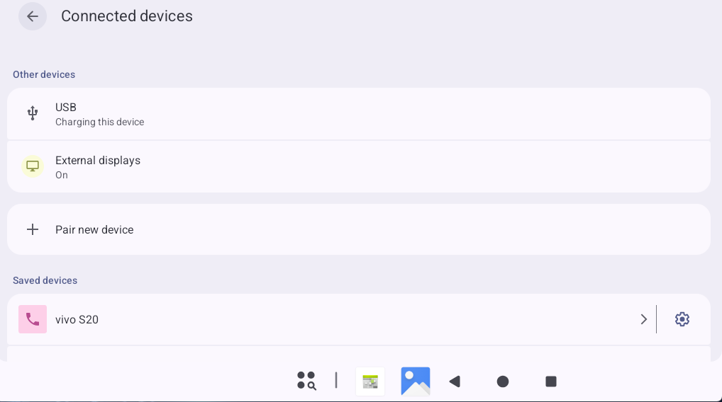
Open the “Settings” app from the App Drawer and tap “Connected devices”.
Tap “USB”.
Select “File Transfer.”
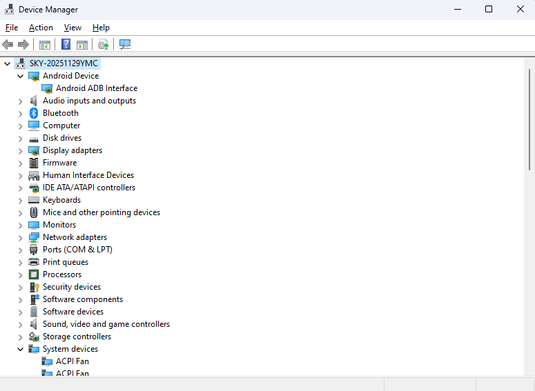
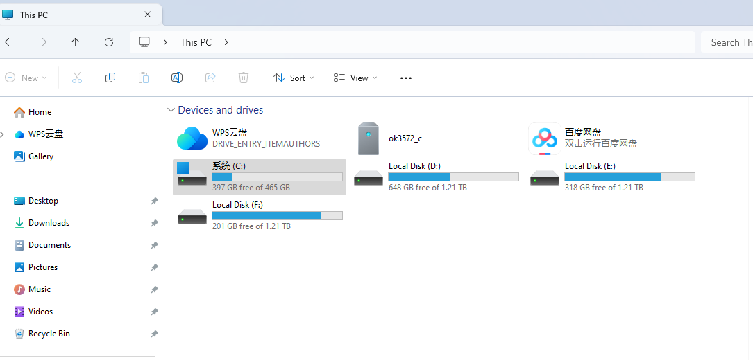
On the computer, open “This PC” (or equivalent file explorer). You should see a device named “ok3572_c” and can now transfer files.
3.19 Serial Port Test
The K3572 carrier board features five serial ports: UART0, UART4, UART8, UART9 and UART11. Of these, UART0 is the debug port, UART4 is the Bluetooth port, UART9 and UART11 are RS-485 ports, and UART8 is a TTL port.
UART |
Device Nodes |
Description |
|---|---|---|
UART0 |
The serial port cannot be directly used for this test. |
|
UART4 |
/dev/ttyS4 |
Used for Bluetooth, not led out separately, cannot be used directly for this test. |
UART9 |
/dev/ttyS9 |
RS485 |
UART11 |
/dev/ttyS11 |
RS485 |
UART8 |
/dev/ttyS8 |
TTL |
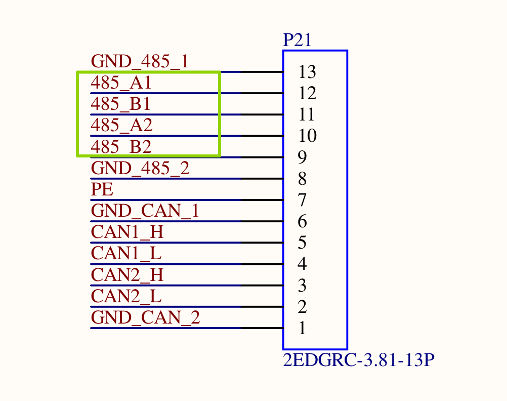
The UART9 and UART11 RS485 are used for the test. Before the test, the pins A and B of the two RS485 interfaces shall be connected, with A connected to A and B connected to B. The carrier board interfaces for the two RS485 are as follows:
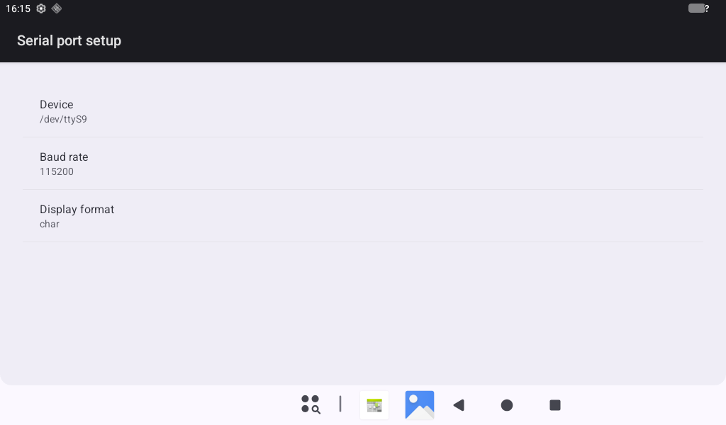
Open the “Serial Port Test” app in the application drawer and click the “Setup” button.
Set “Device” to “ttyS9”.
Set the “Baud rate” to “115200”.
Set ‘Display format’ to “char”.
Click on the “CONSOLE” option in the previous menu to perform a sending and receiving test.
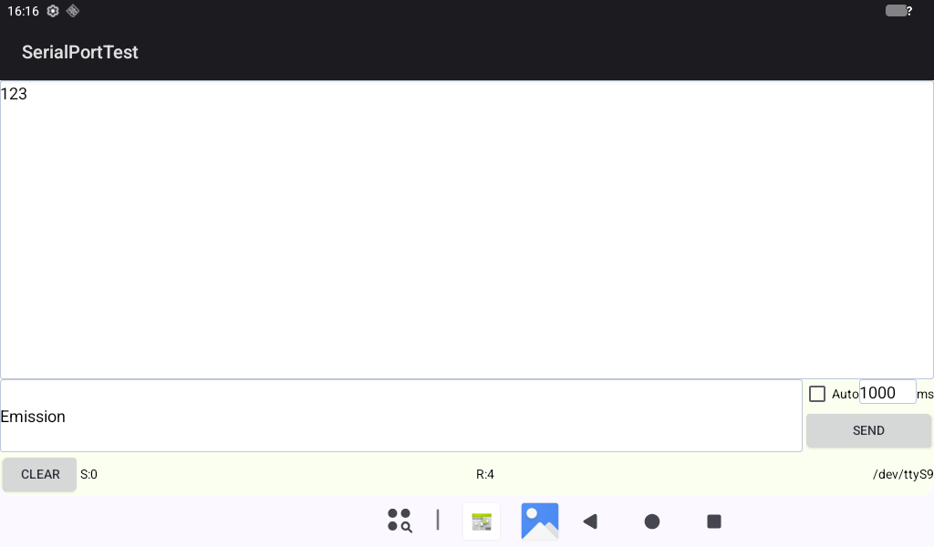
Open ttyS11 in the command line terminal and send data.
console:/ # su
console:/ # stty -F /dev/ttyS11 raw speed 115200
115200
console:/ # echo 123 > /dev/ttyS11
console:/ #
At this point, the app received data from ttyS6, as shown in the figure:
Open ttyS11 in the command line terminal to receive data.
console:/ # stty -F /dev/ttyS11 raw speed 115200
115200
console:/ # cat /dev/ttyS11
Enter the data to be sent in the Emission text box in the app, click SEND to send, as shown in the figure.
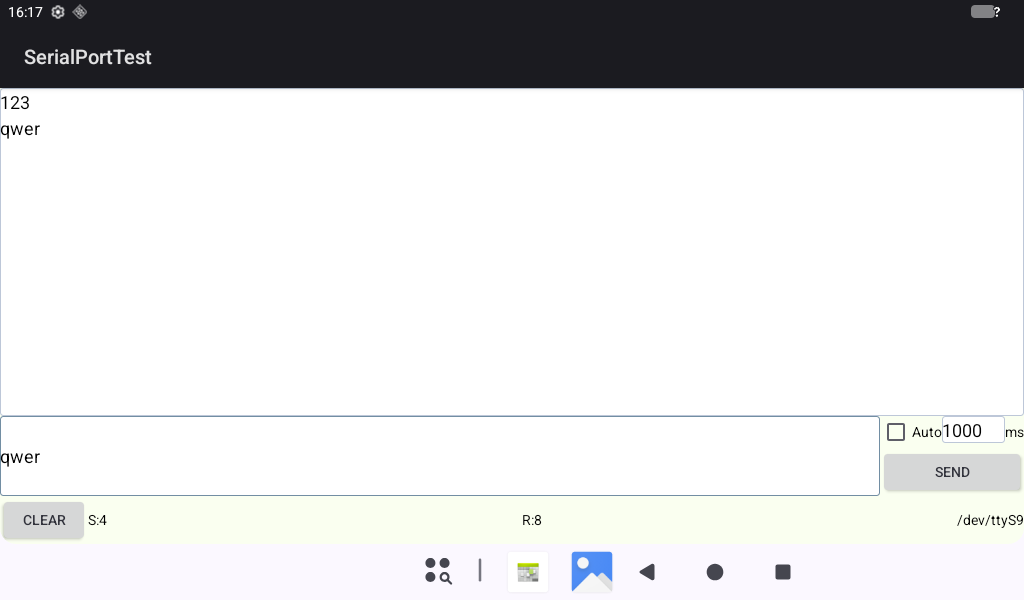
The command line terminal can receive data from ttyS11.
console:/ # stty -F /dev/ttyS11 raw speed 115200
115200
console:/ # cat /dev/ttyS11
qwer
3.20 Camera Test
At present, it supports OV13855 (connected to CAM1 and CAM4 interfaces), OV5645 (connected to CAM2 and CAM3), UVC cameras (connected to USB interface), and defaults to using two OV5645 cameras. Please refer to the Uboot menu section for modifications to Camera usage.
Open the “Camera” app in the application drawer interface and configure relevant permissions.
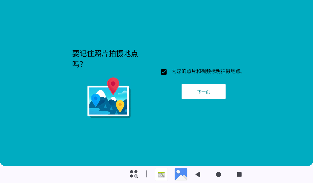
Preview interface.
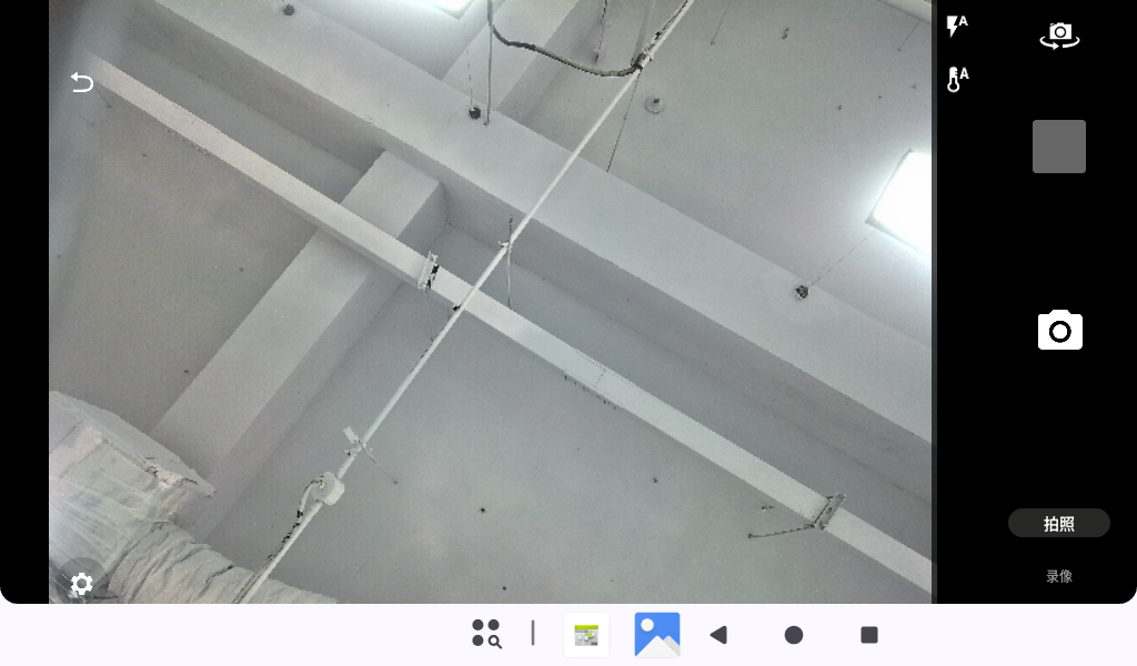
Swipe up the bottom right corner of the preview interface to record, and you can choose to take a photo or video
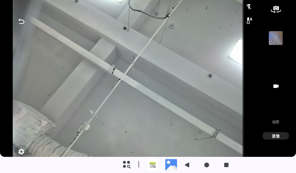
Swipe left on the preview interface and click on the first icon to switch cameras (this camera app only supports two cameras).
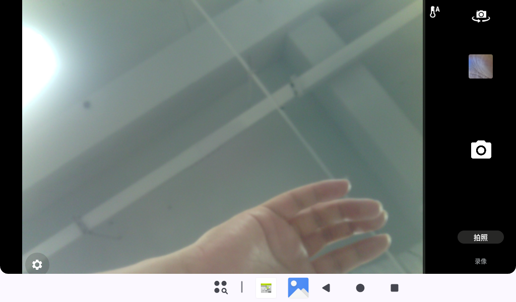
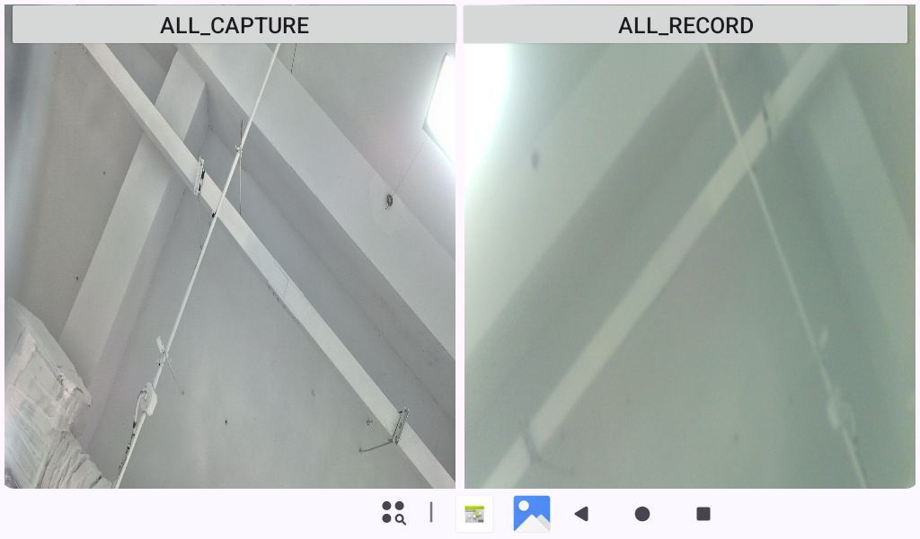
Open the “MultipleCamera” app in the application drawer interface to display multiple camera images (640 * 480) simultaneously.
3.21 HDMI Setting Resolution Test
Open the “Settings” app in the application drawer interface, click “Display”
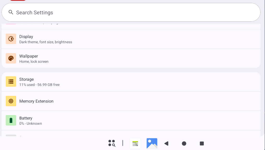
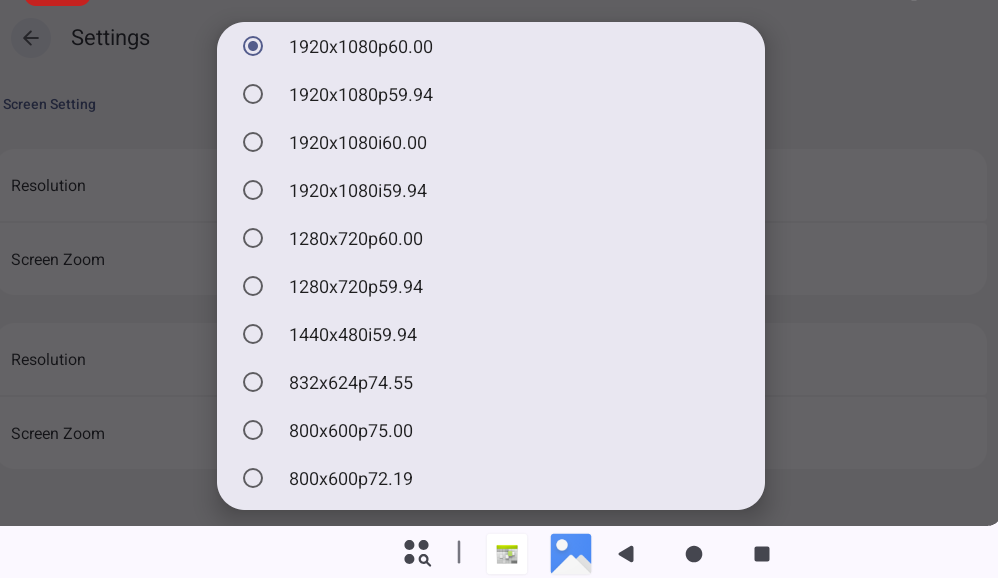
Click on “HDMI” to switch resolution.
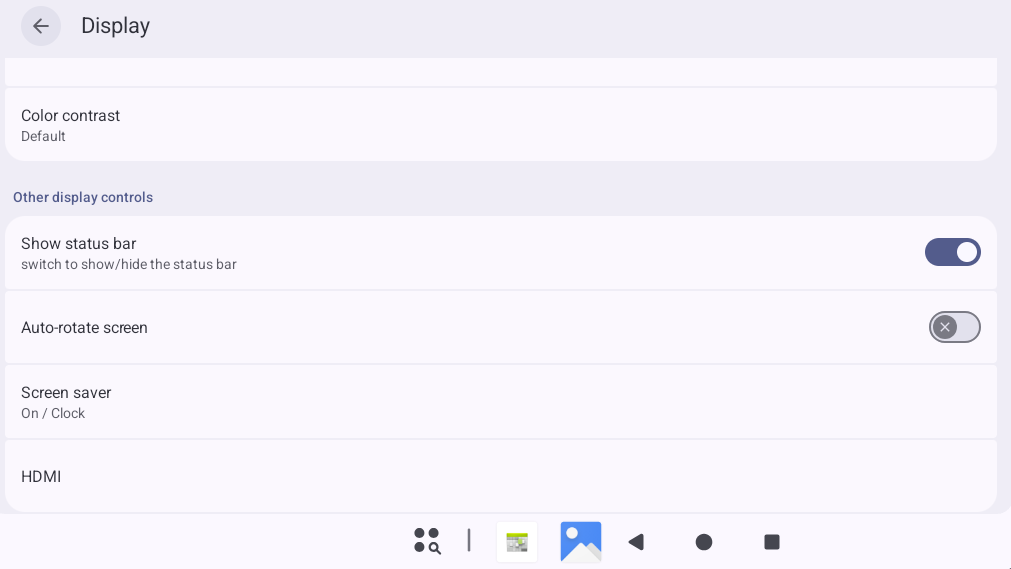
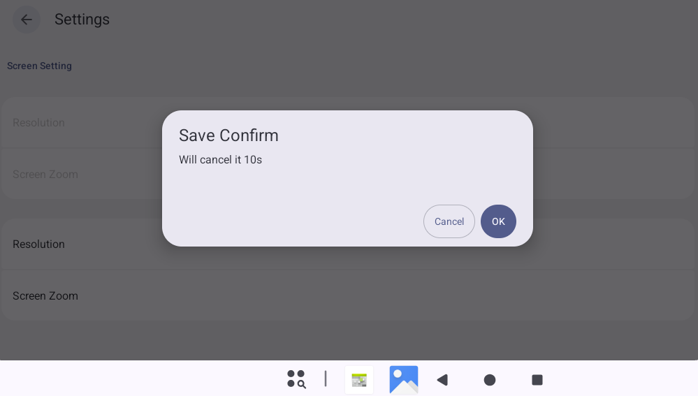
Click the first “Resolution Settings” button to modify the HDMI resolution.
3.22 Restoring Factory Settings
The OK3572 platform supports restoring factory settings.
Open the “Settings” app from the App Drawer and tap “System”.
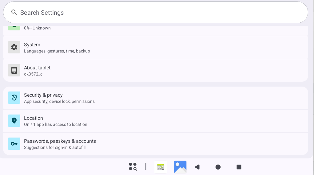
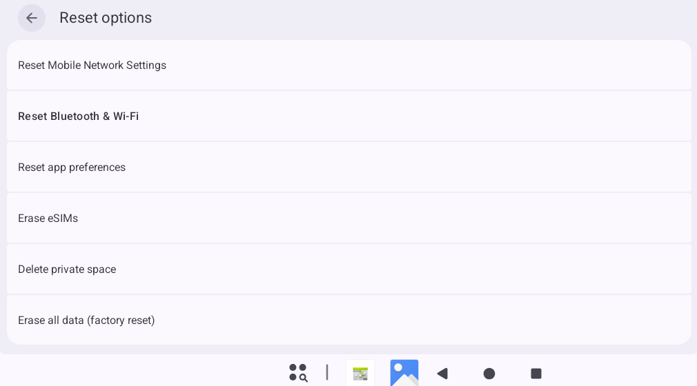
Click “Reset Options”.
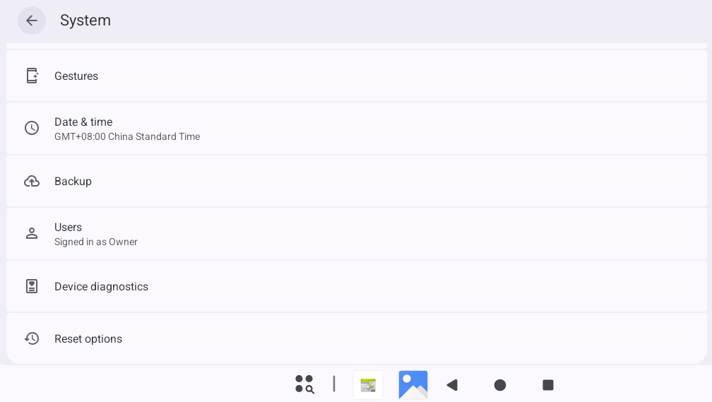
Select the data to be reset according to your specific circumstances, and wait for the OK3572 to restore its factory settings. Please do not disconnect the power supply whilst the factory reset is in progress.
3.23 Installing APK via TF Card
Copy the APK file to the TF card. Open the “Files” app and navigate to the TF card directory as described in previous sections.
Click on the APK file, a pop-up window will appear. Click “Settings.”
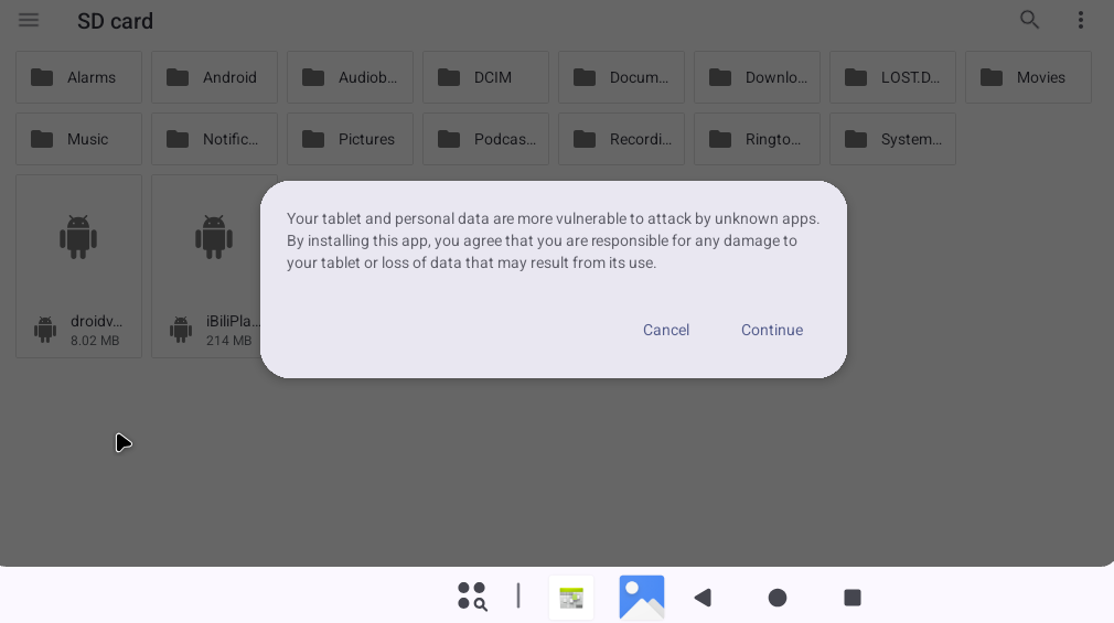
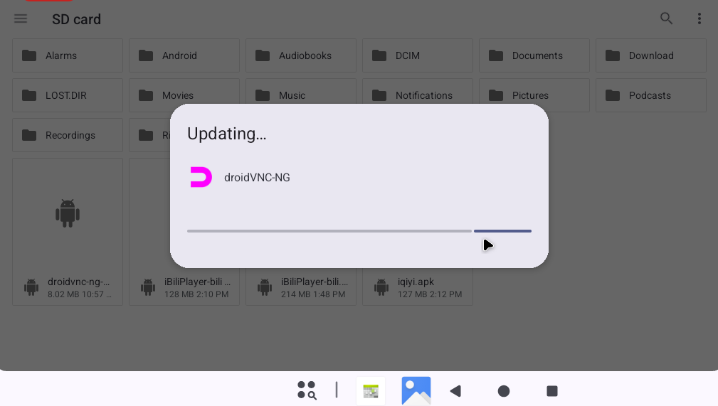
Click “Continue.”
3.24 ROOT Authorization Test
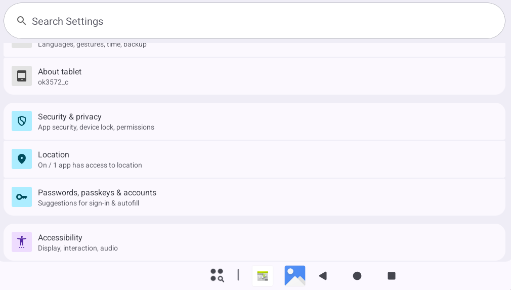
From the app drawer, open the “Settings” app, tap “About tablet.”
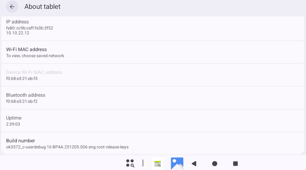
Continuously tap on “Build number” 7 times.
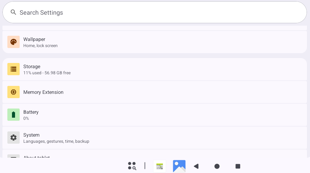
Return to the previous menu, tap “System.”
Tap “Developer options.”
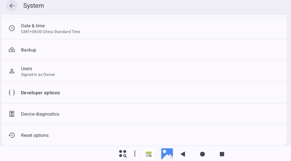
Find the “Root authorization” setting.
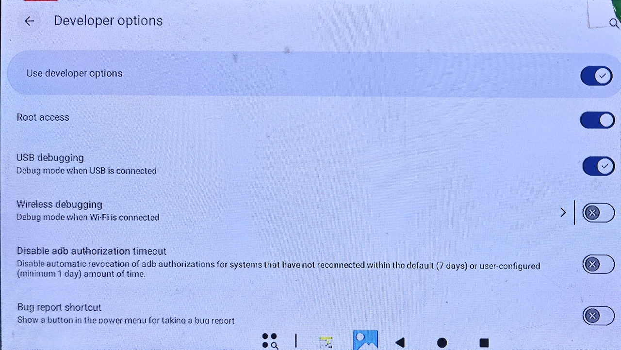
This toggle controls root permissions, including:
su obtaining root permission via serial terminal.
adb root obtaining root permission.
System apps obtaining root permission.
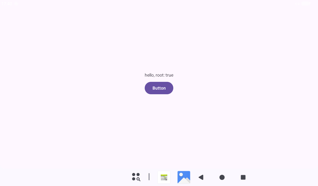
Open the “RootChecker” app from the app drawer to test whether a system app can obtain root permission.
3.25 Screen Lock Test
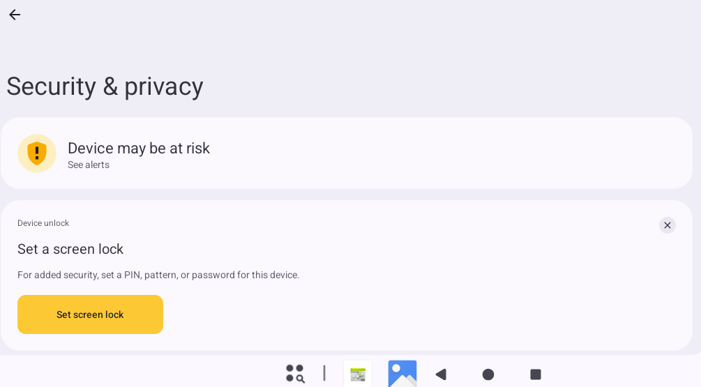
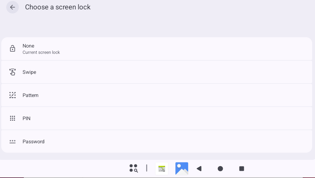
Note: OK3572 does not lock the screen by default.
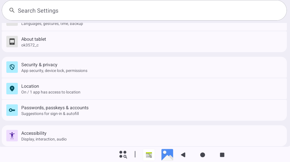
Open “Settings” from the app drawer, tap “Security & privacy.”
Tap “Device unlock.”
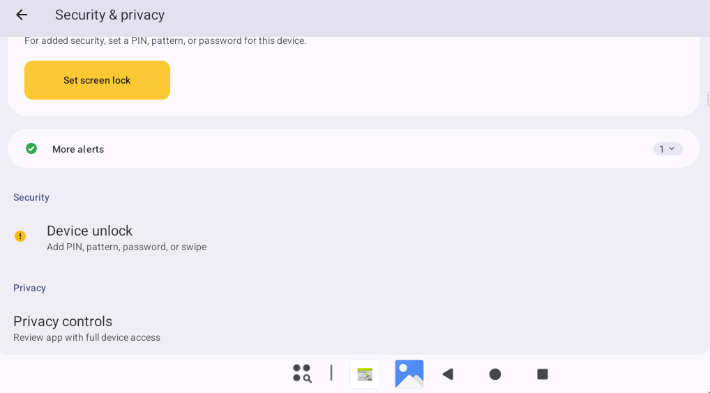
Tap “Screen lock.”
3.26 CAN Test
The OK3572-C features two CAN buses, supporting CAN FD.
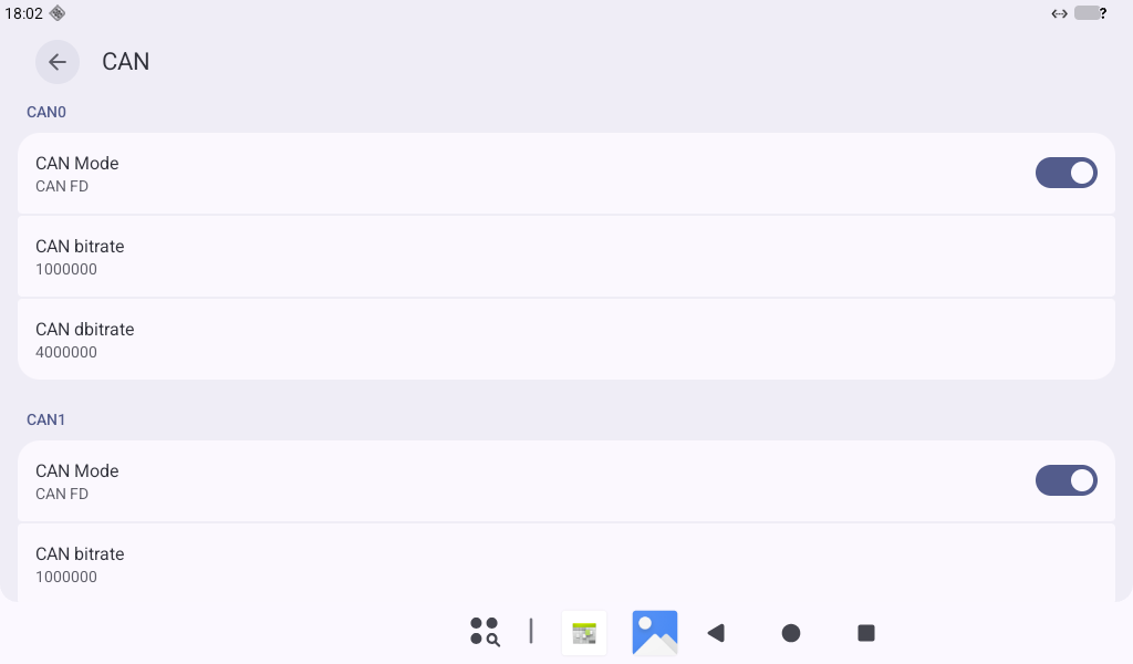
CAN parameters can be configured in the “Settings” app or via the dedicated “can” app.
Open the “Settings” the App Drawer and tap “Network & internet”.
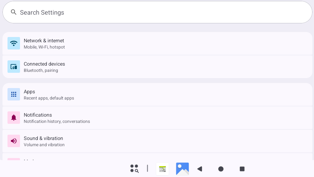
Tap “CAN”.
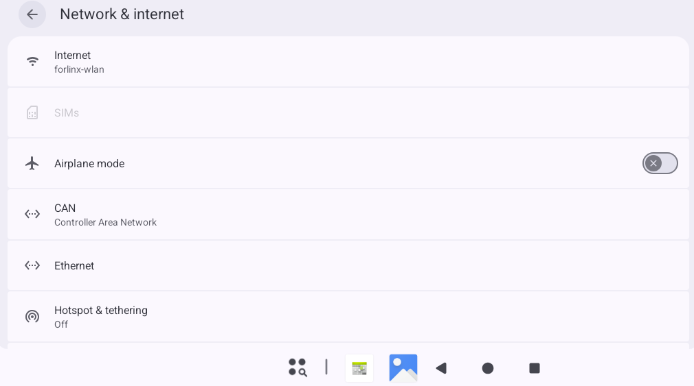
Set the baud rate and mode for can0 and can1.
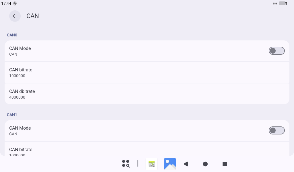
Short the H and L lines for can0 and can1 respectively.
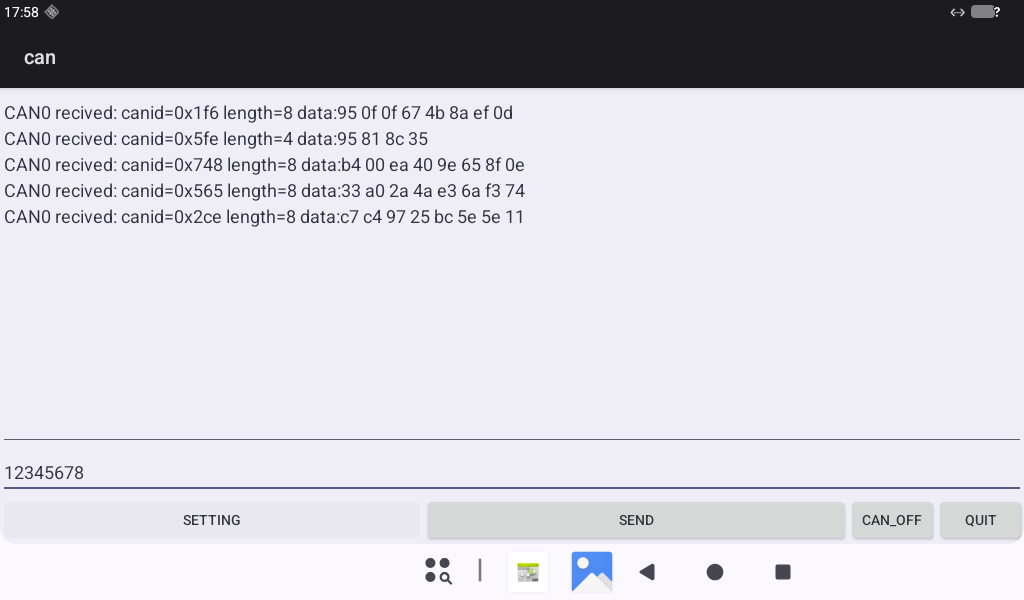
Open the “can” app from the app drawer.
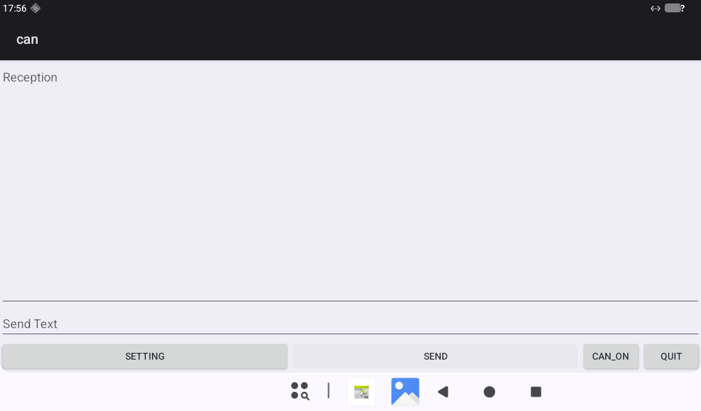
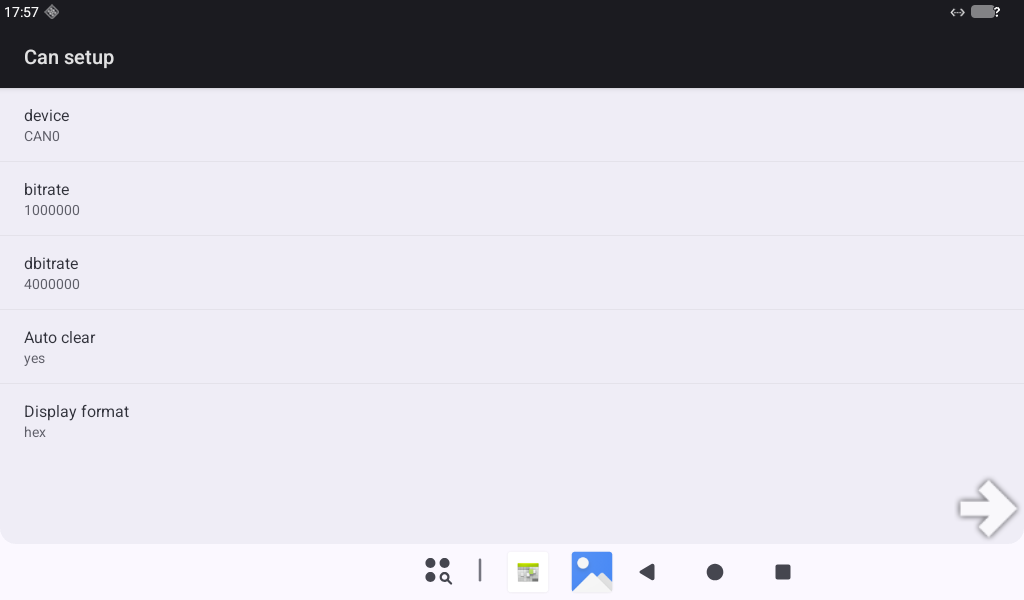
Tap “SETTING” to configure CAN parameters, then tap “CAN_ON” to enable CAN.
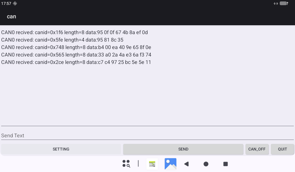
Now, execute the cangen command in the terminal (requires root permission), and data will be visible in the app.
console:/ # cangen -vv -n 5 can1
  can1  720   [1]  50
  can1  3A9   [5]  F0 83 11 7A C0
  can1  497   [7]  6E 47 E2 7D F2 82 A1
  can1  58A   [8]  F4 52 01 19 37 A5 2B 18
  can1  778   [4]  0D 0D 59 32
Execute the candump command in the terminal. Input hexadecimal data in the app’s bottom text box, then click “SEND” to transmit. Data can then be received in the terminal.
console:/ # candump can1
  can1  123   [4]  12 34 56 78
  can1  123   [4]  12 34 56 78
  can1  123   [4]  12 34 56 78
For CAN FD testing, the CAN FD mode key needs to be set at boot.
The testing method is the same as for standard CAN. You can test this independently, and details are omitted here.
3.27 Watchdog Test
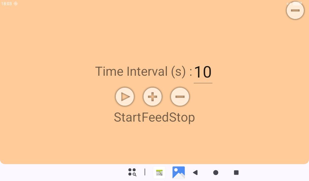
Open the “WatchdogTest” app from the app drawer.
Set the timeout period and click “Start” to activate the watchdog. Click “Feed” to feed the watchdog. If it is not fed within the timeout period, the development board will reboot.
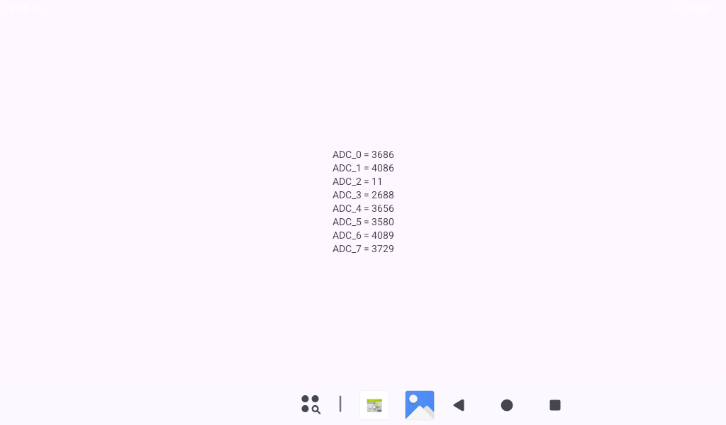
3.28 ADC Test
Open the “ADCTest” app from the app drawer. The displayed value is the reading from the ADC.
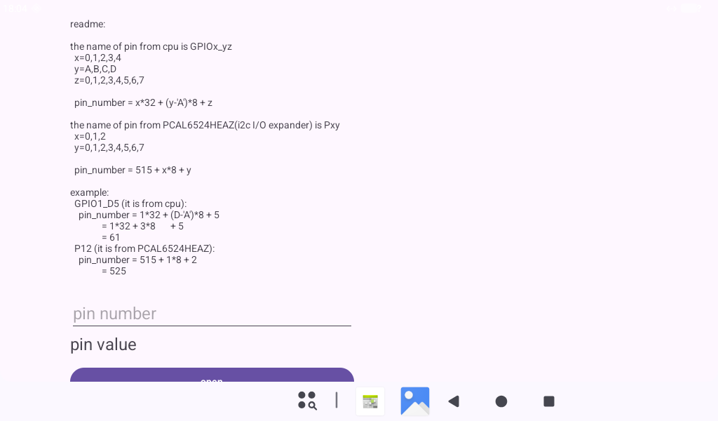
3.29 GPIO Test
OK3572-C’s GPIOs are categorized into CPU-direct and Expanded I/O.
CPU-direct I/O are named in the format GPIOx_yz (where x=0,1,2,3,4; y=A,B,C,D; z=0,1,2,3,4,5,6,7).
pin_number=x*32 + (y-‘A’)*8 + z
Expanded I/O are named in the format Pxy (where x=0,1,2; y=0,1,2,3,4,5,6,7).
pin_number = 515 + x*8 + y
For example:
GPIO1_D5 (CPU-direct)
pin_number = 1*_32 + (D-A) + 5 = 1_32 + 3*8 + 5 = 61
P12 (Expanded)
pin_number = 515 + 1 * 8 + 2 = 525
Open the “GPIOTest” app from the app drawer. Enter the calculated pin_number in the “pin number” text box, click “open” to open the GPIO, and then you can perform read, set to 1, or clear to 0 operations.
3.30 I2C Test
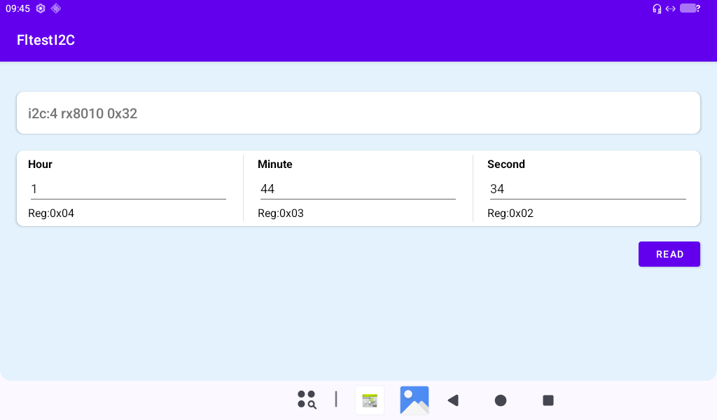
Open the “FltestI2C” app from the app drawer. Click the “Read” button to read the time from the i2c4 RX8010 RTC chip.
3.31 Navigation Bar Settings
The current version supports switching between gesture and button navigation bars. The default is button navigation. To change to gesture navigation, follow these steps:
Open “Settings” from the app drawer.
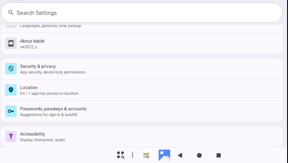
Swipe down and tap “Accessibility.”
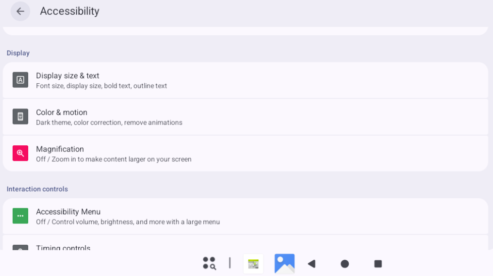
Tap “System controls.”
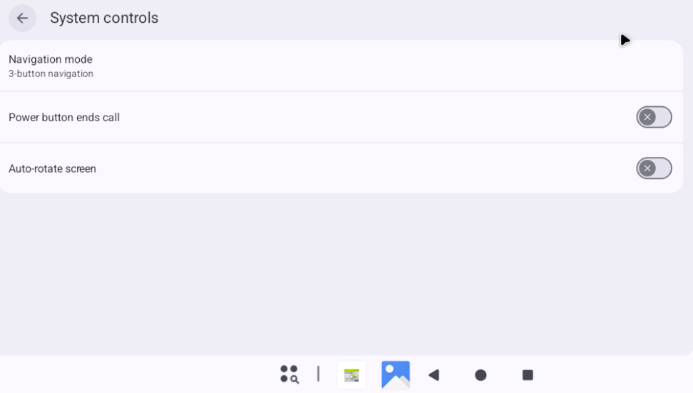
Tap “Navigation mode.”
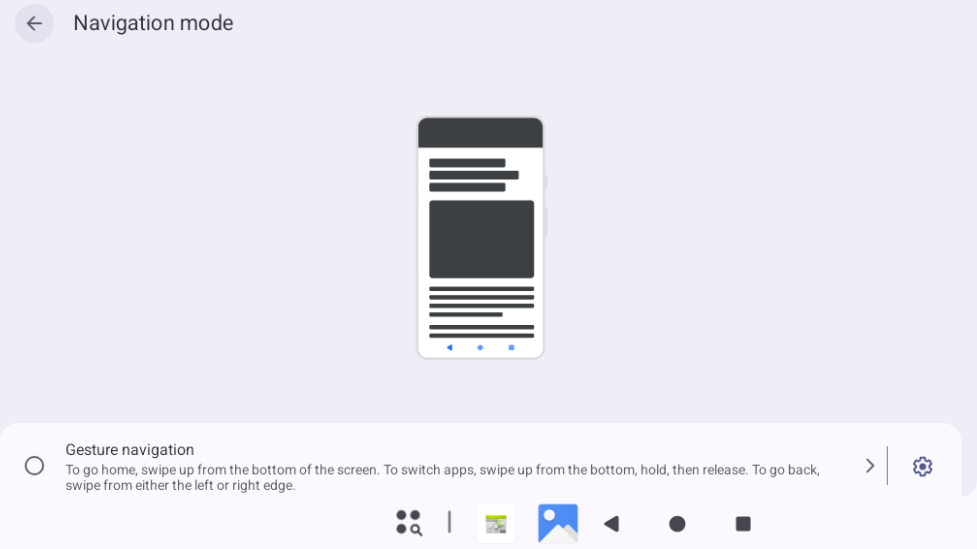
Select “Gesture navigation” to test it.
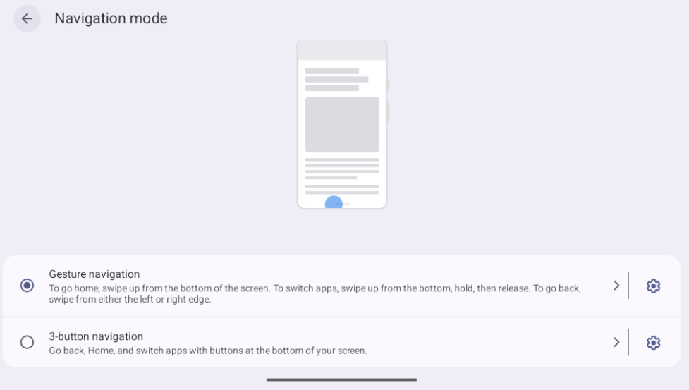
To modify the default factory setting for the navigation bar mode:
Edit the file at SDK/device/rockchip/rk3572/overlay/frameworks/base/core/res/res/values/config.xml.
Change the value of config_navBarInteractionMode to 2.
3.32 Uboot Menu
Open the “OK3572ForlinxHwConfig” app from the app drawer to configure functions like screen switching and the main display.
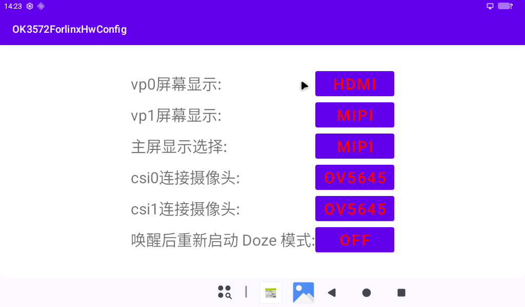
vp0 screen display: Currently only supports HDMI.
vp1 screen display: Currently only supports MIPI.
Main display selection: Currently supports choosing between HDMI and MIPI.
csi0 connected camera: ov5645, ov5645x2 (split into two ov5645 streams), ov13855.
csi1 connected camera: ov5645, ov5645x2 (split into two ov5645 streams), ov13855.
Automatic Doze mode after wake-up and reboot: Default is OFF.
3.33 Silent Installation
Open the “SilentInstallTest” app from the app drawer.
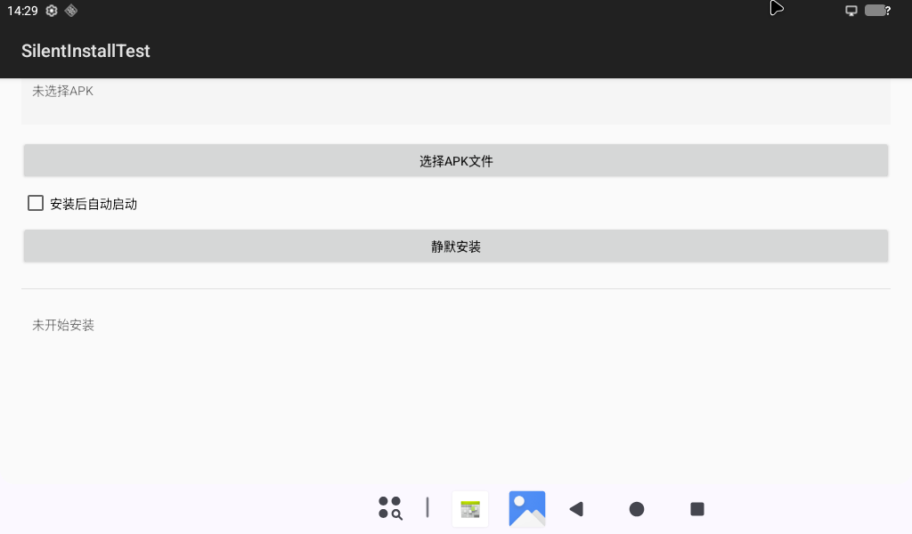
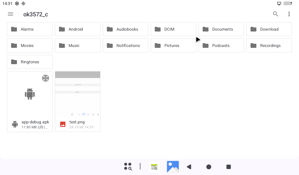
Click “Select APK file” to choose the app to install.
Click “Silent Install.”
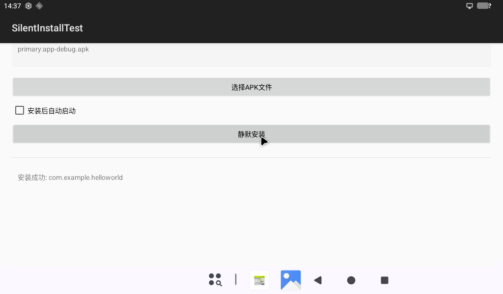
Currently only supports regular user apps.
4. System Flashing
4.1 OTG System Flashing
4.1.1 OTG Driver Installation
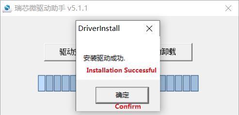
️ Tool Path: 《 3-Tools\DriverAssitant_v5.14.zip》
Extract the file above to any directory and run it with administrator privileges.
Open the DriverInstall.exe program.
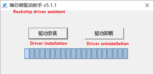
Click Install Driver.
4.1.2 OTG Flashing Test
4.1.2.1 RKDevTool Flashing Test
Path: 3-Tools\RKDevTool_v3.37_for_window.zip
It is a development tool provided by Rockchip. Extract it to a directory with only English characters, then connect the development board to the host using a Type Typc0 cable. Press and hold the recovery button on the development board, then press the reset button to reset the system. After about two seconds, release the recovery button. There will be prompts on the Rockchip development tool : loader device found
Note: Device detection occurs when the recovery button is pressed during the power-on of the development board.
The extraction directory for Rockchip’s development tools can be arbitrary, but users have reported that the directory should contain only English characters. If the development tool interface does not match the image shown below, consider extracting it to a directory with only English characters.
Open the Rockchip development tool:

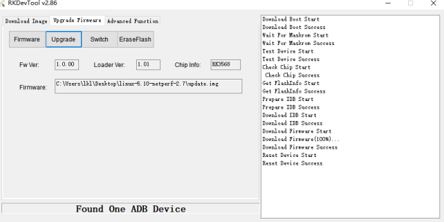
Click the “Upgrade Firmware” tab, click the “Firmware” button to select the full upgrade image update.img. The programme will analyse the firmware, so please wait a moment.

Click “Advanced Functions” -> “Erase All” to erase the operation.
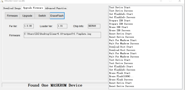
Click the “Upgrade Firmware” button -> “Upgrade” to begin upgrading.
MASKROM Mode Introduction
If loader mode is inaccessible (loader problem, etc.), press and hold the Maskroom key, then press the reset key to enter maskrom mode for burning.
At this time, the system will prompt that a maskrom device is found. The programming process is consistent with the loader mode. It is better to use the update. img for programming.
Note: Don’t click “Device Partition Table” in maskrom mode, it is invalid.
Flashing a single image in MASKROM mode does not clear the UBoot environment variables.
Introduction to the function of burning and writing images separately.
This feature is suitable for downloading individual images. This feature can only be used in loader burn mode.
Click on the ① Download Image tab.
Click on ② Device Partition Table to read the image partition location.
Click the ③ Checkbox to select the image that needs to be burned separately.
Click ④ to select the image.
Click ⑤ to execute and burn.
After burning, restart.
4.1.2.2 FactoryTool Flashing Test
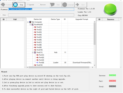
FactoryTool is used for batch OTG flashing in the factory. It does not require reading an image file and can batch-flash large images. If RKDevTool does not meet compatibility requirements, this method can also be attempted. Before using, extract it to a directory with only English characters. Connect the development board and host using a Type-C cable. Press and hold the recovery button, press the reset button for the system reset, and after about two seconds, release the recovery button. There will be prompts on the Rockchip development tool : loader device found
Note: Device detection occurs when the recovery button is pressed during the power-on of the development board.
The extraction directory for Rockchip’s development tools can be arbitrary, but users have reported that the directory should contain only English characters. If the development tool interface does not match the image shown below, consider extracting it to a directory with only English characters.
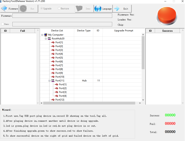
After selecting the firmware, click Start. The loader device will be detected, and the flashing process will begin automatically.
4.2 TF System Flashing
Flashing TF card making and testing
Note: Testing indicates that the maximum supported TF card capacity is 16 GB. Using a TF card of 32 GB or larger may result in flashing failure.
Copy SDDiskTool_v1.69.zip from the user profile tool directory to any windows directory. Run SD_Firmware_Tool.exe with administrator privileges.
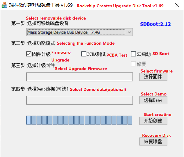
Select the disk device, tick the “Firmware Update” box, and select update.img. Click to start creating.
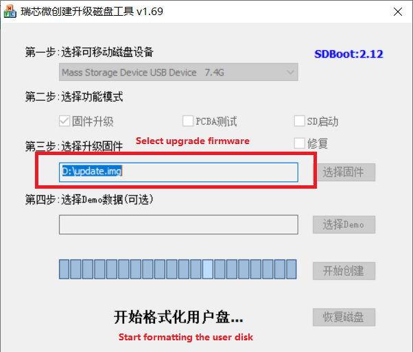
Insert the TF card into the development board and power it on; the system will automatically begin the flashing process. Once the flashing is complete, both the screen and the serial port will display the following message:
Please remove SD CARD!!!, wait for reboot.
At this point, remove the TF card and the system will restart automatically (please do not switch off the power directly).
At this time, remove the TF card, and the system will automatically restart (do not cut the power directly).
1. Kernel boot phase: Heartbeat light mode, flashing at regular intervals;
2. Preparation stage for programming: The eMMC indicator light is off;
3. Programming in progress: The eMMC indicator light remains lit;
4. Post-programming stage: Heartbeat light mode, with regular, intermittent flashing;
If the device does not restart automatically after removing the TF card, you can complete the flashing process by restarting it manually. Please wait patiently whilst the data is being written.
5. System OTA Upgrade Test
OTA (Over The Air) upgrade is the standard software upgrade method provided by the Android system. It is powerful and supports both local full-package upgrade and network upgrade in the current system version.
OTA upgrade packages are divided into full upgrade packages and incremental upgrade packages. A full upgrade package contains the complete system, while an incremental upgrade package includes only the differences between V2.0 and V1.0 systems. To use an incremental upgrade package, the development board must currently be running V1.0 system.
For specific compilation procedures, refer to the “OK3572-C_Android16_User Compilation Manual”.
Note: The OK3572-C 2GB RAM version does not currently support the Android 16 system.
5.1 OTA Upgrade
5.1.1 Local Upgrade
Copy the compiled full or incremental upgrade package to the root directory of a USB drive, TF card, or the /storage/emulated/0 directory. The system will automatically detect the upgrade package and pop up an upgrade dialog.
Example operation via ADB:
adb root
adb remount
adb push ok3572_c-ota.zip /storage/emulated/0/update.zip
After uploading the upgrade package via ADB, restart the development board to trigger the system to detect the upgrade package. Click “Install”.
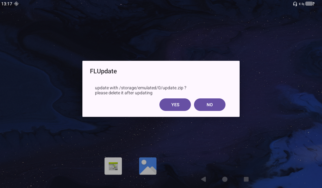
Click “Install”
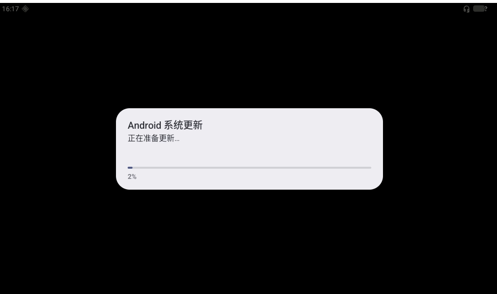
The debug window will display the following information:
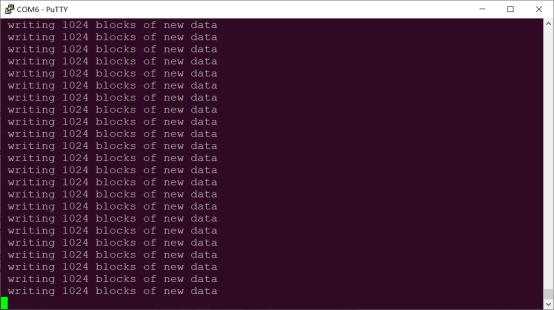
Afterward, the system will automatically reboot into Recovery mode and complete the OTA package upgrade. Do not power off during this process.
Once the upgrade is complete, the system will automatically reboot to the Android home screen.
Note: After the system reboots, a firmware upgrade prompt is normal. Since the update.zip file exists, it may take a few minutes for the prompt to appear. Deleting update.zip will prevent the firmware upgrade dialog from reappearing.
5.1.2 Remote Upgrade
Service End
Currently, a static HTTP server is used. The server root directory must contain a version.json file, which the development board retrieves via a GET request to determine whether an upgrade is needed.
The contents of the document are as follows:
{
    "products": [
        {
            "name": "OK3572-C",
            "version": "1.0",
            "path": "./update.zip"
        },
        {
            "name": "OK3572-C",
            "version": "1.1",
            "path": "./update.zip"
        }

    ]
}
Multiple products can be added to the array.
product: Must be unique.
version: Must follow the format x.x.x (a string in decimal form).
path: Relative address of the image directory.
Development Board Side
device/rockchip/rk3572/ok3572_c/ok3572_c.mk
ro.vendor.ota.host=192.168.1.212:8000ota_server
ro.vendor.ota.product.name=OK3572-Cproduct_name: Must match the
cmd.json.
ro.vendor.ota.product.version=1.0version: Must match the
cmd.json.Before upgrading, the system checks the current version against the server’s image version. An upgrade occurs only if the server version is higher than the current version.
Currently, the actual version number of the
update.zipis not validated—only thecmd.jsonis compared. Ensure consistency betweencmd.jsonand theupdate.zip.
vendor/forlinx/FLUpdate/
OTA Remote Upgrade Process
Check network status (Ethernet or WiFi only). If connected successfully, connect to the server and read
cmd.json.Determine whether an upgrade is needed based on the
cmd.json.If an upgrade is required, download the image (stored in
/storage/emulated/0/update_dl.zip.
Http Server
gohttpserver_1.1.4_windows_amd64 is a simple HTTP server tool available at: https://github.com/codeskyblue/gohttpserver](https://github.com/codeskyblue/gohttpserver)
It meets OTA usage requirements. For specific usage, refer to https://github.com/codeskyblue/gohttpserver