RK Series Development Boards – Self-Selected Screen Adaptation
Document classification: □ Top secret □ Secret □ Internal information ■ Open
Copyright
The copyright of this manual belongs to Baoding Folinx Embedded Technology Co., Ltd. Without the written permission of our company, no organizations or individuals have the right to copy, distribute, or reproduce any part of this manual in any form, and violators will be held legally responsible.
Forlinx adheres to copyrights of all graphics and texts used in all publications in original or license-free forms.
The drivers and utilities used for the components are subject to the copyrights of the respective manufacturers. The license conditions of the respective manufacturer are to be adhered to. Related license expenses for the operating system and applications should be calculated/declared separately by the related party or its representatives.
Overview
This article describes the methods and principles for screen adaptation using various interfaces of Forlinx’s RK series products. By referring to it, you can gain insights into considerations and reference methods for adapting self-selected screens.
Revision History
Date |
Version |
Revision History |
|---|---|---|
17/10/2025 |
V1.0 |
Initial Version |
RK Platform Display Subsystem
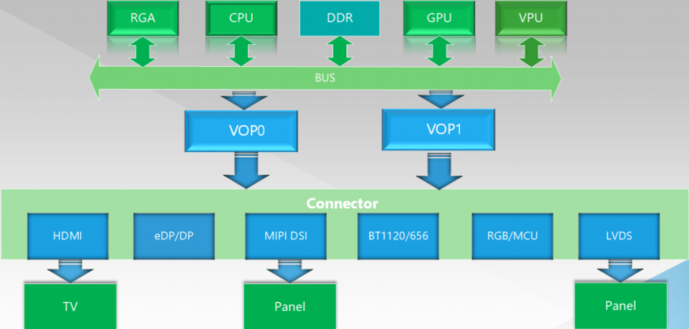
RK Platform Display Subsystem. DSS (Display SubSystem). RK platform display subsystem version: VOP 1.0 and VOP 2.0. VOP.
VOP 1.0
VOP 2.0
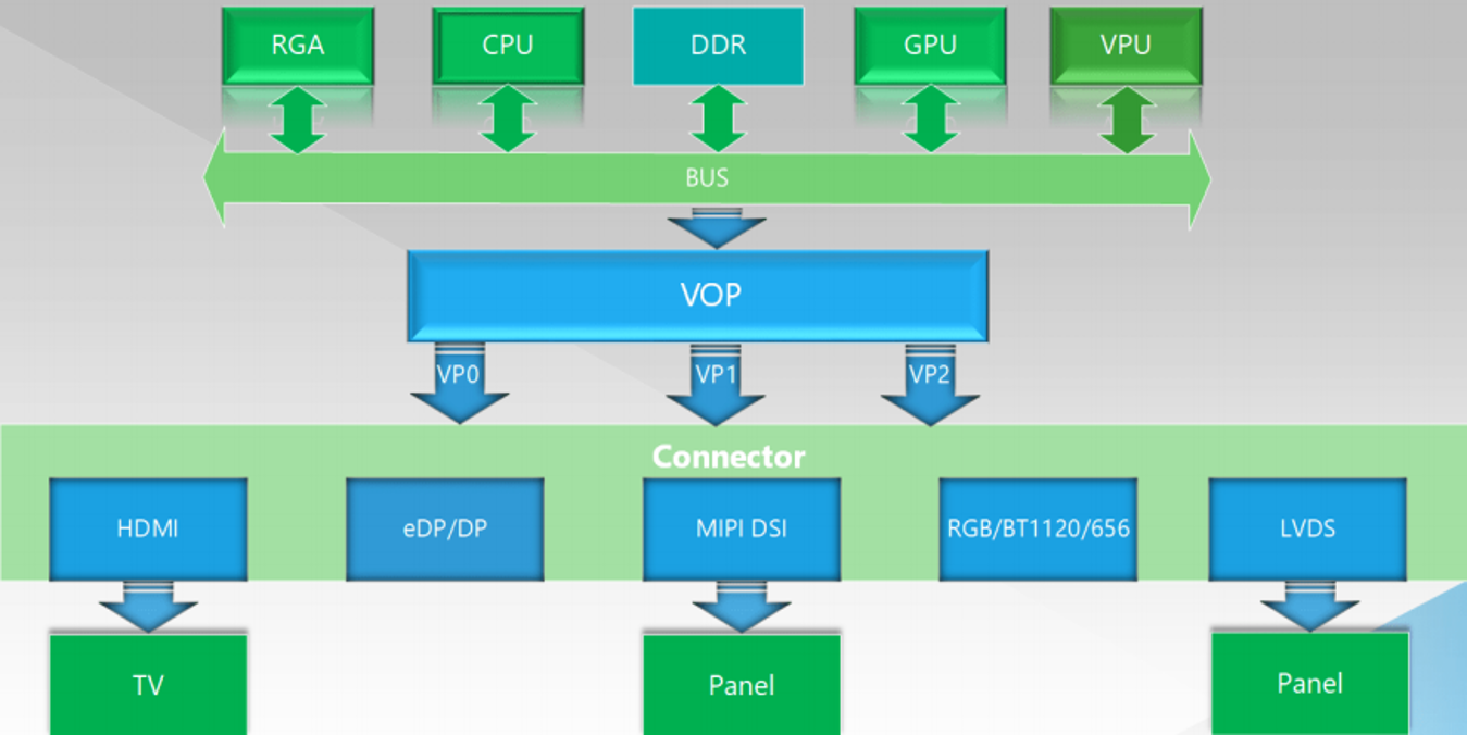
The key difference between the two VOP generations lies in whether the display panel is managed by VOP or by VP.
The adaptation for self-selected screen only requires changes to the display parameters at the outermost layer of the display subsystem (DSS), particularly in the panel section.
Display Parameter Modifications
Reference Document:
User documentation source code /docs/cn/Common/DISPLAY/Rockchip_DRM_Panel_Porting_Guide
Display Parameters
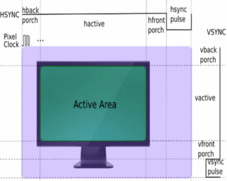
Display Parameter Acquisition and Modification
Common Description |
Device Tree Property |
Meaning/Source |
|---|---|---|
Synchronization Signals |
hsync / vsync |
Display parameters / Panel manual |
Hback |
hback / vback |
Display parameters / Panel manual |
Resolution |
hactive / vactive |
Display parameters / Panel manual |
Hfront |
hfront / vfront |
Display parameters / Panel manual |
Signal |
bus-format |
Display parameters / Panel manual |
Initialisation Sequence |
panel-init-sequence |
Required only for MIPI screens / to be provided by the screen manufacturer |
Clock |
clock-frequency |
Pixel Clock (PCLK) / Display Panel Manual |
These display parameters have corresponding entries in the device tree framework. After obtaining the parameters according to their sources, filling them into the appropriate locations completes the display setup.
Below describes the locations for entering parameters for different interfaces and important considerations when dealing with various interfaces.
RGB Interface
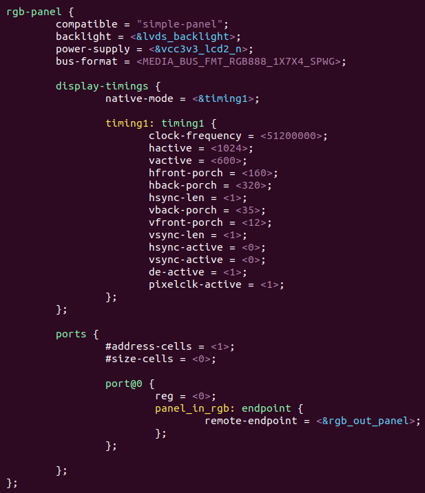
RGB Signal Format Switching:
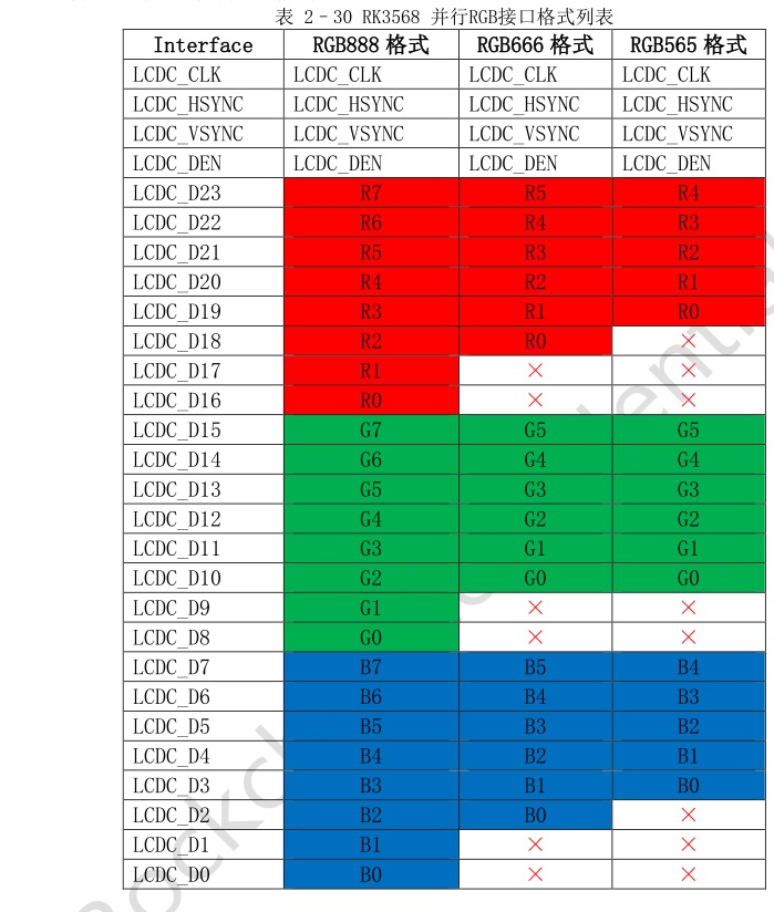
The file drivers/gpu/drm/rockchip/rockchip_drm_vop2.c defines the following optional RGB signal formats: RGB565, RGB666 and RGB888.


RGB Pin Connection Mapping
LVDS Interface
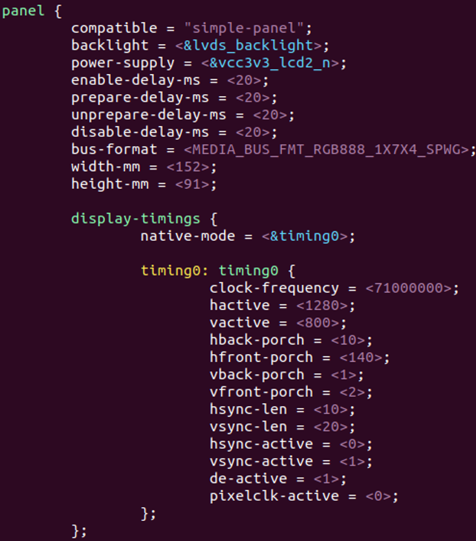
LVDS Signal Format Switching:


The property 1X7X3 indicates three pairs of data lanes, typically referred to as Single-Six/Dual-Six signal format screens.
The property 1X7X4 indicates four pairs of data lanes, typically referred to as Single-Eight/Dual-Eight signal format screens.
LVDS Single/Dual Channel Switching:
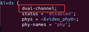
Configure the output channel mode under the Video Output Controller (DSS connector-level node — refer to display subsystem diagrams for questions).
Default is single channel; add dual-channel; to switch to dual channel.
MIPI Interface
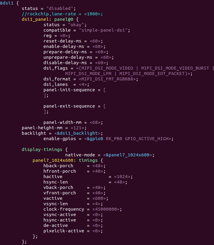
MIPI Initialization Sequence Acquisition:
Screen manufacturers generally provide an initialization sequence for MIPI screens, similar to the example below.
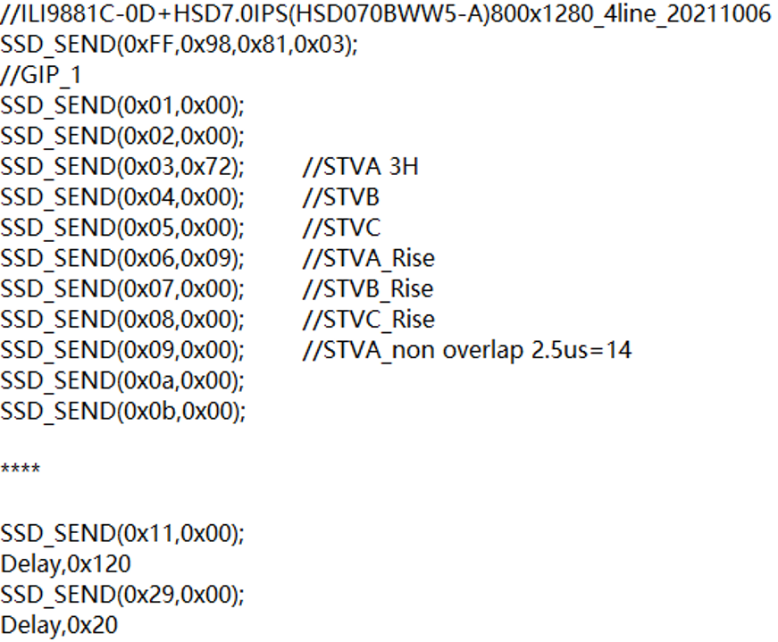
Please convert this sequence into the format reserved in Rockchip’s display subsystem.
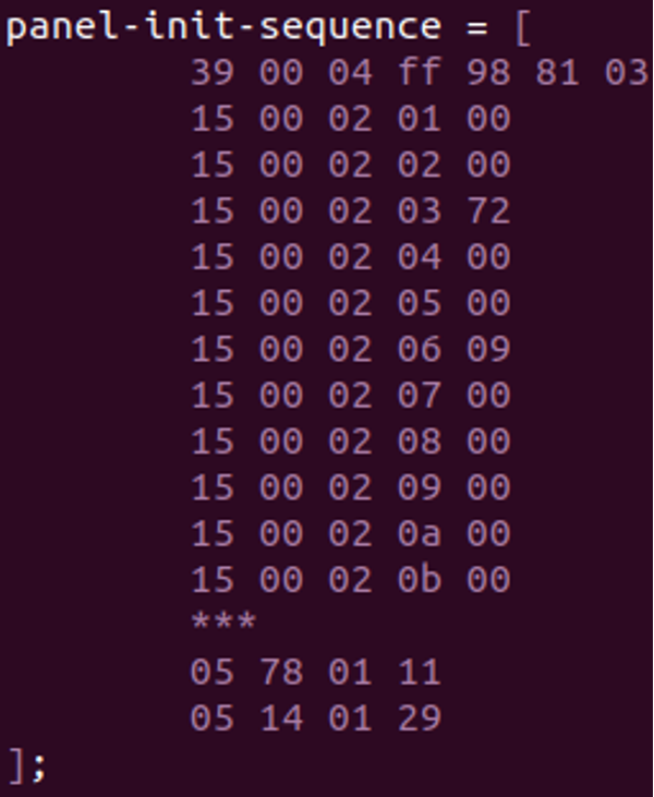
Initialization Sequence Conversion Rules:
Example: 39 00 04 ff 98 81 03
| | | | Parameter Parameter Parameter
| | | Command
| | Length
| Delay
Command Type
Command types include the following three:
39: Long packet (parameters > 2)
15: Short packet (parameters ≤ 2)
05: Issue DCS command only (no parameters)
05 78 01 11 indicates a delay of 0x78=120ms before issuing command 11.
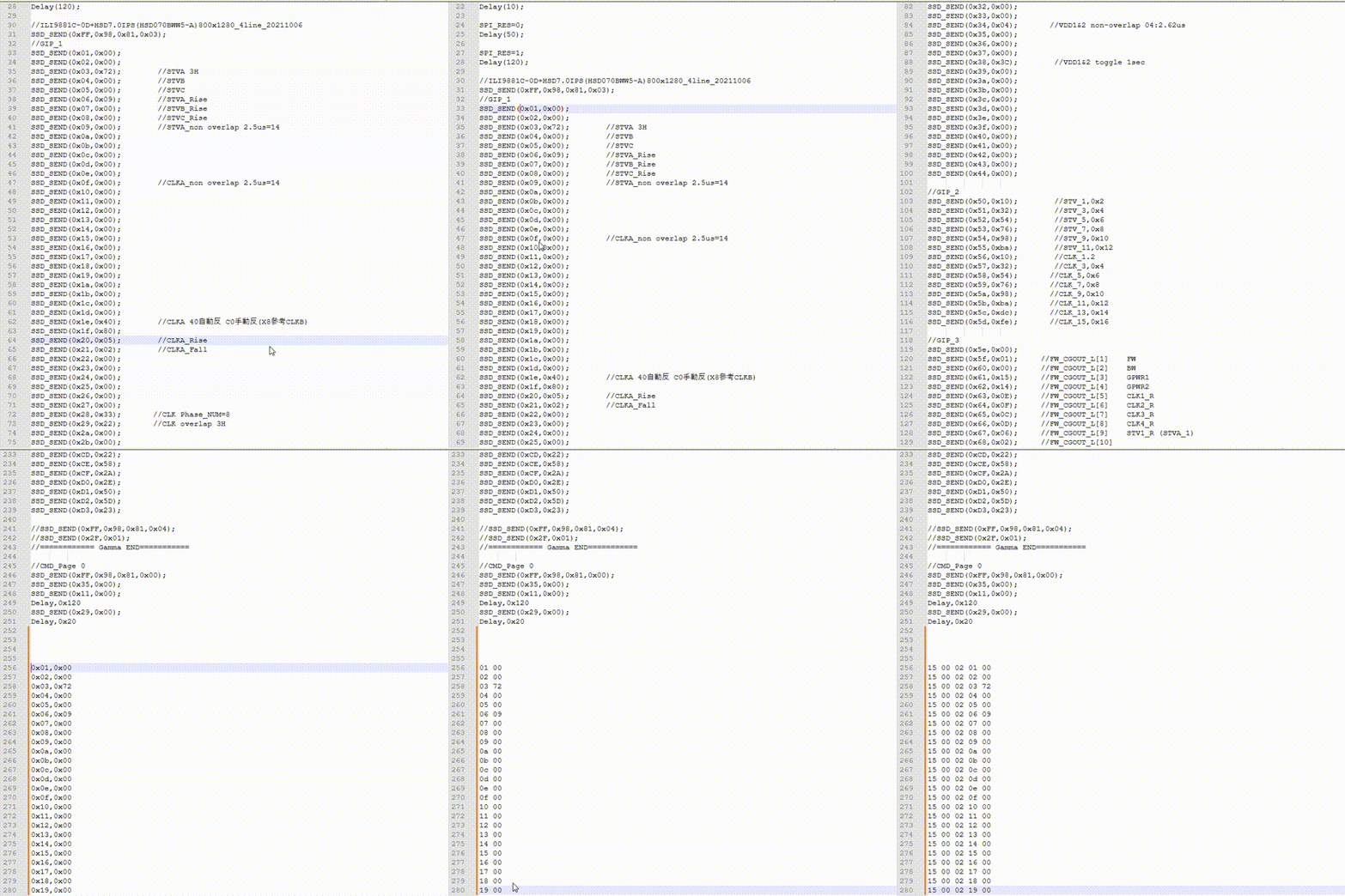
Use VSCode or Notepad++ to achieve the formatting effect shown in the diagram, using the shortcut shift+alt+mouse click
MIPI Single/Dual Channel Switching:
Modify the rockchip, lane-rate property value in the device tree. A value greater than 4 represents the MIPI signal mode/lanes. Change it directly to match the screen’s required number of lanes.
Note: During the actual screen adjustment process, the provided screen specifications may not be entirely accurate. For example, when the display appears abnormal (such as color distortion or misalignment), the normal approach is to adjust the pixel format and fine-tune the clock. However, an alternative way of thinking can be considered: In the initial screen adjustment stage, the exact screen clock frequency or its valid range might be uncertain. If the screen displays basically normal, the clock frequency is likely to be roughly correct. Conversely, if the screen displays abnormally and the normal adjustment approach yields limited improvement, adjusting the screen’s frame rate may be helpful—for instance, reducing it from 60fps to 30fps, or other values. The core idea is to adjust the clock frequency over a broader range in order to troubleshoot.
HDMI & eDP Interface:
HDMI & eDP typically auto-detect EDID, requiring no manual modification of display parameters.
Of course, there are also methods for setting a fixed resolution
Reference links for setting a fixed HDMI resolution:
eDP Fixed Resolution Method Reference:
rockchip_drm_integration_helper-zh.pdf page 34.
Use the display-timings structure, writing the timing directly into the DTS file.
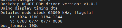
After successfully setting a fixed resolution via the device tree, the following print will appear during the U-Boot boot phase: using display timing dts
Display Issue Debugging Methods:
cat /sys/kernel/debug/dri/0/summaryCheck the VP status to see if it is outputting;Under the
/sys/class/drm/, force output the controller status, or view the connection status and resolution information recognized by the controller.
Touch Adaptation
Touch devices are differentiated by interface and type.
USB touch / I2C touch — different interfaces are configured with different touch chips.
Resistive touch / capacitive touch — different types have distinct accuracy and sensitivity characteristics.
USB touch devices are generally plug-and-play (driver-free).
I2C touch follows the standard Linux I2C chip adaptation process:
A. Add a description of the I2C chip to the device tree.
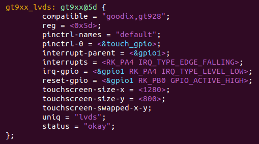
B. Add the corresponding driver to the kernel and compile it into the kernel.

Capacitive touchscreens do not require touch calibration; their touch orientation is set through driver configuration.
Resistive touchscreens require touch calibration; their touch orientation is configured via the calibration process.
Touch Calibration
Only resistive touchscreens require touch calibration.
USB Resistive Touch Calibration Method — Forlinx Embedded RK Development Manual documentation
Potential Issues:
Q: MIPI screen shows no backlight at all.
Confirm that the initialization sequence is sent correctly. You can communicate with the screen manufacturer to obtain a gamma test sequence. The screen will display as long as this test sequence is successfully sent;
Confirm the pin order of the MIPI signal lines is correct. The MIPI initialization sequence is sent only through the DSI0 differential pair. If connected incorrectly, the initialization sequence cannot be sent.
Q: MIPI screen displays the logo and then the image disappears.
Confirm whether the reset pin of the MIPI screen changes level during the boot process. Issues have been encountered where, due to pin definition conflicts, the screen’s reset pin is pulled low after the system starts and sends the initialization sequence, causing the screen to reset and requiring the sequence to be resent. However, because the system has already booted, this results in only the logo being displayed, with the subsequent system interface failing to appear;
Confirm the screen parameters (timings). Feedback has been received indicating that incorrect screen parameters can lead to phenomena such as the image slowly fading away..
Q: eDP displays intermittently (probability issue).
OK3568 5.10.160 Uboot eDP Repeated Training — Forlinx Embedded RK Development Manual documentation